國立臺灣大學工學院機械工程學系 博士論文
Department of Mechanical Engineering College of Engineering
National Taiwan University Doctoral Dissertation
奈米流體熱傳導係數的研究 及奈米磁性流體於變壓器上的應用
Investigation of Thermal Properties of Nanofluids and the Application of Ferrofluids on Transformers
蔡宗翰
Tsai, Tsung-Han
指導教授:陳炳煇教授、吳文方教授
Advisor: Prof. Chen, Ping-Hei, Prof. Wu, Wen-Fang
中華民國 九十九 年 六 月 June 2010
Acknowledgement
It is hard to express my sincere gratitude by words to those who provided me with support and advice to help bring out this thesis.
My deepest gratitude goes first and foremost to Professor Ping-Hei Chen and Professor Wen-Fang Wu, my advisors, for your constant encouragement and guidance. I have benefited a lot from your illumination and instruction not only in studies but also in life experience. Appreciations are also expressed to the member of oral examination committee, Dr. Chao-Kuang Chen, Dr. Da-Sheng Lee, Dr. Chih-Cheng Lu, Dr.
Chin-Ting Yang, Dr. Yao-Joe Yang and, for your valuable suggestions and constructive criticism.
Second, I would like to express the gratitude to my friends and lab mates who gave me their help and time in listening to me and helping me work out my problems during the difficult course of the thesis.
Last, my thanks would go to my family, my mother and my beloved, Ching-Yie, for your considerations and confidence in me all through these years. Without your supports, I cannot complete this work.
摘要
本論文主要討論奈米流體的熱傳導係數及奈米磁性流體的應用。在第一個主 題中,我們討論了基礎流體的黏滯性對奈米流體的熱傳導係數的影響。實驗結果 顯示,在低黏度的基礎流體中,奈米顆粒對奈米流體的熱傳導係數有明顯的增益。
對於低黏度的奈米流體,量測到的熱傳導係數高於 Maxwell 模型所估計的值。當 基礎流體的黏滯性增加時,量測到的奈米流體的熱傳導係數會越來越趨近於 Maxwell 模型的估計值,這表示了奈米流體的黏滯性會影響它們的熱傳導係數,以 及懸浮的奈米顆粒的布朗運動大大地增進了奈米流體的熱傳導係數。此外,由於 奈米磁性流體具有一些特殊的性質,因此衍生了新的應用。在第二個主題中,奈 米磁性流體及四氧化三鐵塊被用來作為變壓器的磁芯。本論文使用的變壓器建構 於毛細管及晶圓上。我們針對不同磁芯的變壓器的效能做了量測及模擬。雖然四 氧化三鐵的存在增加了電感值及耦合係數,但是由於外加磁場與材料磁化有相位 差的關係,電阻值也跟著增加而影響效能。最後,我們提出了一個製造固態磁芯 的製程。在低於 4MHz 頻率下,具有固態磁芯的變壓器的效能會高於空氣芯變壓器 的效能。
關鍵詞:熱傳導係數、奈米流體、布朗運動、奈米磁性流體、變壓器
Abstract
The thermal conductivity of nanofluids and the application of ferrofluids are investigated. With respect to the first topic, the effect of the viscosity of base fluids on the thermal conductivity of nanofluids is discussed. Experimental results reveal an obvious enhancement on thermal conductivity of nanofluids with low viscous base fluids. The measured thermal conductivity of low viscous nanofluids markedly exceeds that predicted by Maxwell prediction model. As the viscosity of the base fluid increases, the measured thermal conductivity of the nanofluid gradually approaches the value predicted by Maxwell prediction model, indicating that the viscosity of nanofluids influences their thermal conductivity, and the Brownian motion of suspended particles importantly enhances the thermal conductivity of nanofluids. Moreover, while the first topic is investigated, some special properties of ferrofluid are found. Therefore, a new application is derived. With respect to the second topic, ferrofluids and bulk Fe3O4 are applied as the magnetic cores of transformers. The transformers used in this thesis are constructed on a capillary or on a wafer. The performance of transformers with different magnetic cores is measured and simulated. Although Fe3O4 increases the inductance and coupling coefficient, it also increases the resistance owing to a lag between the external magnetic field and the magnetization of the material. Finally, a new process for
fabricating a solid magnetic core is proposed, in which ferrofluids are used to deliver ferro-nanoparticles into microchannels. A transformer with a solid magnetic core outperforms the same transformer that with an air core below a frequency of 4 MHz.
Keywords: Thermal conductivity, nanofluids, Brownian motion, ferrofluids,
transformers
Nomenclature
k thermal conductivity
φ volume fraction of particles d diameter
T temperature
T0 initial temperature
t time
κ thermal diffusivity
r radial distance
q heat per unit length per unit time Ei exponential integral function
F force
G torque
H* distance between the cup and cylinder Ra radius of cylinder
Len length of cylinder Ω angular velocity of cylinder DB Brownian diffusion coefficient
kB Boltzmann constant
μ viscosity
K coupling coefficient
L inductance
R resistance
Z impedance
ω angular frequency
Q quality factor
μ∗ permeability
μ’ real part of permeability
μ'' imaginary part of permeability N number of coil turns
A cross section area l length of solenoid
E electric field
B magnetic field
H magnetizing field
J free current density D electric displacement field
ρ free charge density
tanδ magnetic tangent loss Subscript:
Maxwell Maxwell prediction model p particle
bf base fluid
nano nanofluid
Table of Contents
Acknowledgement ... I Abstract ... II Nomenclature ... V Table of Content ... VIII List of Tables ... XI List of Figures ... XII
Chapter 1 Introduction ... 1
1.1 General Remarks ... 1
1.2 Literature Survey ... 5
1.2.1 Thermal Conductivity of Nanofluids ... 5
1.2.2 Ferrofluids ... 12
1.2.3 Transformers ... 14
1.3 Motivation and Objectives ... 18
1.4 Outline of the Thesis ... 20
Chapter 2 Fabrication Processes and Experimental Apparatus .. 23
2.1 Fabrication of Nanofluids ... 23
2.1.1 Fabrication of Water-Based Al2O3 Nanofluids ... 23
2.1.2 Fabrication of Oil-Based Fe3O4 Nanofluids ... 24
2.2 Fabrication of Transformers ... 26
2.2.1 Fabrication of Transformer on a Capillary ... 26
2.2.2 Fabrication of MEMS Transformer on a Wafer ... 27
2.3 Experimental Procedure and Apparatus ... 30
2.3.1 Physical Properties of Nanofluids ... 30
2.3.2 Performance of Transformers ... 35
Chapter 3 Physical Properties of Nanofluids ... 65
3.1 Water-Based Al2O3 Nanofluids ... 65
3.1.1 Physical Properties of Water-Based Al2O3 Nanofluids ... 65
3.1.2 Viscosity of Water-Based Al2O3 Nanofluids ... 66
3.1.3 Thermal Conductivity of Water-Based Al2O3 Nanofluids ... 66
3.2 Oil-Based Fe3O4 Nanofluids ... 68
3.2.1 Physical Properties of Oil-Based Fe3O4 Nanofluids ... 68
3.2.2 Viscosity of Oil-Based Fe3O4 Nanofluids ... 69
3.2.3 Thermal Conductivity of Oil-Based Fe3O4 Nanofluids ... 69
3.3 Discussions ... 72
Chapter 4 Application of Fe
3O
4Nanofluid on Transformers ... 95
4.1 Definitions of Coupling Coefficient and Quality Factor ... 95
4.2 Transformer on a Capillary ... 97
4.3 MEMS Transformer on a Chip ... 100
4.4 HFSS Simulation ... 101
4.4.1 Simulation of Transformer on a Capillary ... 103
4.4.2 Simulation of MEMS transformer on a Chip ... 105
4.5 Discussions ... 106
Chapter 5 Conclusions and Prospects ... 139
References ... 143
List of Tables
Table 1.1 ... 22
Thermal conductivities of various solids and liquids
Table 2.1 ... 62
The chemical reagents used in the experiment
Table 2.2 ... 63
Testing conditions of nanofluids
Table 2.3 ... 64
Testing conditions of transformers
Table 3.1 ... 93
Physical properties of Al2O3 nanoparticles
Table 3.2 ... 94
Physical properties of Fe3O4 nanofluids
List of Figures
Figure 2.1 ... 37
The flow chart of the precipitation procedure
Figure 2.2 ... 38
The adsorption model showing the relation between the surfactant and the particle: (a) Model for water-based Fe3O4 nanofluid (b) Model for oil-based Fe3O4 nanofluid
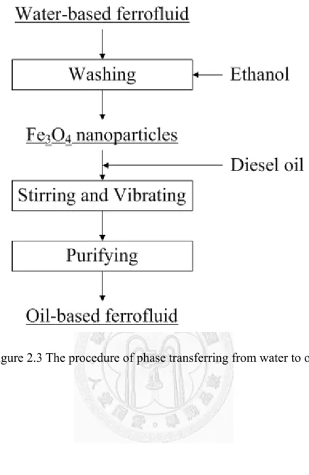
Figure 2.3 ... 39
The procedure of phase transferring from water to oil
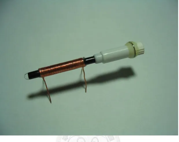
Figure 2.4 ... 40
The photo of the transformer on a capillary which carries the oil-based Fe3O4 nanofluid
Figure 2.5 ... 41
The fabrication process of the MEMS transformer
Figure 2.6 ... 43
The diagram of the coating rotation speed versus time: (a) EPG-512; (b) VM652; (c) polyimide
Figure 2.7 ... 46
The masks for the photoresist: (a) EPG-512; (b) polyimide; (c) dry film
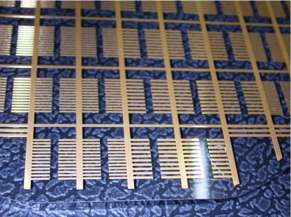
Figure 2.8 ... 47
The photo of processed wafer after line patterning
Figure 2.9 ... 48
The photo of processed wafer after metal etching
Figure 2.10 ... 49
The photo of processed wafer after Cu and Au electroplating
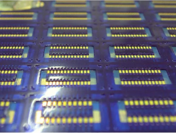
Figure 2.11 ... 50
The photo of processed wafer after dry film patterning
Figure 2.12 ... 51
The photo of processed wafer after via electroplating
Figure 2.13 ... 52
The diagram of wafer cutting line
Figure 2.14 ... 53
The schematic diagram of wire bonding
Figure 2.15 ... 54
The measuring sample of MEMS transformer
Figure 2.16 ... 55
The circuit diagram of high voltage output device
Figure 2.17 ... 56
The photo of high voltage output device
Figure 2.18 ... 57
The photo of testing sample
Figure 2.19 ... 58
The schematic structure of Searle viscometer
Figure 2.20 ... 59
The free body diagram of the cylinder
Figure 2.21 ... 60
The photo of the precision impedance analyzer and the spring clip fixture
Figure 2.22 ... 61
The photo of dummy PCB
Figure 3.1 ... 74
FESEM SEI of Al2O3 nanoparticles
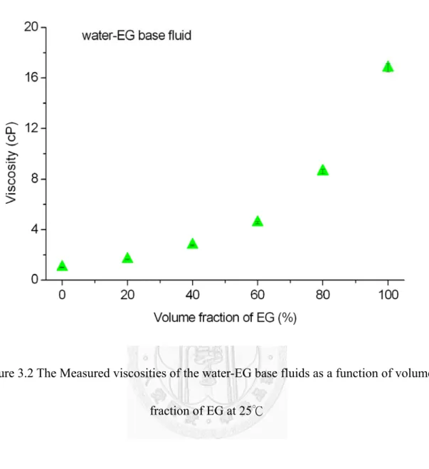
Figure 3.2 ... 75
The Measured viscosities of the water-EG base fluids as a function of volume fraction of EG at 25℃
Figure 3.3 ... 76
The Measured viscosities of the EG-glycerol base fluids as a function of volume fraction of glycerol at 25℃
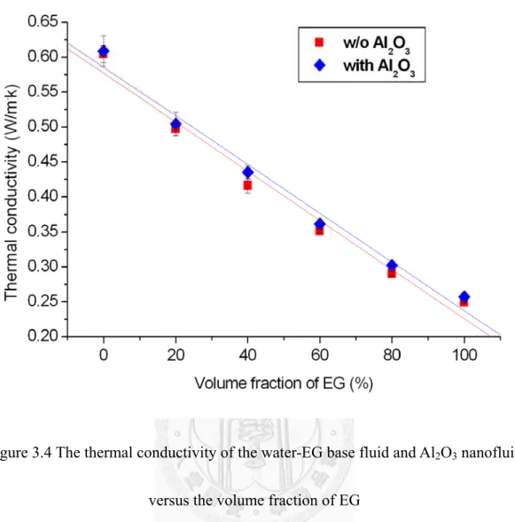
Figure 3.4 ... 77
The thermal conductivity of the water-EG base fluid and Al2O3 nanofluid versus the volume fraction of EG
Figure 3.5 ... 78
The thermal conductivity of the EG-glycerol base fluid and Al2O3 nanofluid versus the volume fraction of glycerol
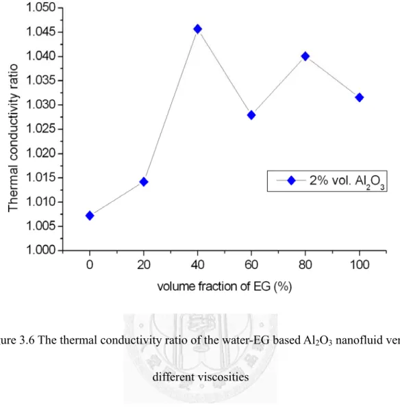
Figure 3.6 ... 79
The thermal conductivity ratio of the water-EG based Al2O3 nanofluid versus different viscosities
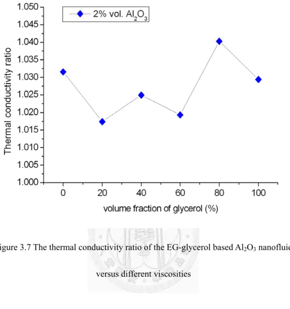
Figure 3.7 ... 80
The thermal conductivity ratio of the EG-glycerol based Al2O3 nanofluid versus different viscosities
Figure 3.8 ... 81
The magnetic effects on the Fe3O4 nanofluid
Figure 3.9 ... 82
The TEM photo of Fe3O4 nanoparticles
Figure 3.10 ... 83
The crystalline phases of the Fe3O4 nanoparticles
Figure 3.11 ... 84
The magnetized curve of the Fe3O4 nanofluid measured by a VSM
Figure 3.12 ... 85
The measured viscosities of the diesel oil-PDMS base fluids as a function of volume fraction of PDMS at 25℃
Figure 3.13 ... 86
The thermal conductivity ratios, knano/kbf and kMaxwell/kbf of viscous nanofluids versus volume fraction of Fe3O4 nanoparticles at the viscosity of 4.18 cP
Figure 3.14 ... 87
The thermal conductivity ratios, knano/kbf and kMaxwell/kbf of viscous nanofluids versus volume fraction of Fe3O4 nanoparticles at the viscosity of 31.8 cP
Figure 3.15 ... 88
The thermal conductivity ratios, knano/kbf and kMaxwell/kbf of viscous nanofluids versus volume fraction of Fe3O4 nanoparticles at the viscosity of 140.4 cP
Figure 3.16 ... 89
The thermal conductivity ratios, knano/kbf and kMaxwell/kbf of viscous nanofluids versus volume fraction of Fe3O4 nanoparticles at the viscosity of 648 cP
Figure 3.17 ... 91
Effect of the viscosity of the base fluid on the thermal conductivity ratio of nanofluids:
(a) knanofluid/kbf and (b) knanofluid/kMaxwell
Figure 3.18 ... 92
The contact angles between bulk Fe3O4 and components of viscous base fluids: (a) diesel oil; (b) PDMS
Figure 4.1 ... 109
The schematic measurement of self inductance and leakage inductance
Figure 4.2 ... 110
The effective circuit model of real inductors containing the series resistance and parasitic capacitance
Figure 4.3 ... 111
The self-inductance of coils of transformers with different magnetic cores
Figure 4.4 ... 112
The leakage inductance of coils of transformers with different magnetic cores
Figure 4.5 ... 113
The coupling coefficient of transformers with different magnetic cores
Figure 4.6 ... 114
The resistance of coils of transformers with different magnetic cores
Figure 4.7 ... 115
The quality factor of coils of transformers with different magnetic cores
Figure 4.8 ... 116
The quality factor of coils of transformers with different magnetic cores at low
frequency
Figure 4.9 ... 117
The self-inductances and leakage inductances of coils of MEMS transformer with the air core and magnetic core of 1 M Fe3O4 nanofluid
Figure 4.10 ... 118
The coupling coefficient of MEMS transformers with the air core and magnetic core of 1 M Fe3O4 nanofluid
Figure 4.11 ... 119
The resistance of coils with the air core and magnetic core of 1 M Fe3O4 nanofluid
Figure 4.12 ... 120
The quality factor of coils with the air core and magnetic core of 1 M Fe3O4 nanofluid
Figure 4.13 ... 121
The HFSS model of transformer on a capillary
Figure 4.14 ... 122
The convergence curve of simulation with the model of transformer on a capillary
Figure 4.15 ... 123
The simulated self-inductance of coils of transformers with different magnetic cores
Figure 4.16 ... 124
The simulated leakage inductance of coils of transformers with different magnetic cores
Figure 4.17 ... 125
The simulated coupling coefficient of transformers with different magnetic cores
Figure 4.18 ... 126
The simulated resistance of coils of transformers with different magnetic cores
Figure 4.19 ... 127
The simulated quality factor of coils of transformers with different magnetic cores
Figure 4.20 ... 128
The HFSS model of MEMS transformer with the PCB
Figure 4.21 ... 129
The HFSS model of dummy PCB
Figure 4.22 ... 130
The convergence curve of simulation with the model of MEMS transformer
Figure 4.23 ... 131
The simulated self-inductance and leakage inductance of coils of MEMS transformer with the air core and magnetic core of 1 M Fe3O4 nanofluid
Figure 4.24 ... 132
The simulated coupling coefficient of MEMS transformer with the air core and magnetic core of 1 M Fe3O4 nanofluid
Figure 4.25 ... 133
The simulated resistance of coils of MEMS transformer with the air core and magnetic core of 1 M Fe3O4 nanofluid
Figure 4.26 ... 134
The simulated quality factor of coils of MEMS transformer with the air core and magnetic core of 1 M Fe3O4 nanofluid
Figure 4.27 ... 136
The macroscopic view of Fe3O4 nanoparticles: (a) without a magnetic field; (b) with a magnetic field.
Figure 4.28 ... 138
The microscopic view of Fe3O4 nanoparticles: (a) without a magnetic field; (b) with a magnetic field.
Chapter 1 Introduction
1.1 General Remarks
Nanofluids that comprise suspended nanoparticles in a base fluid has been used in numerous engineering applications, including microfluidic devices, heat exchangers, and optical switches. Choi [1] first coined the term “nanofluid” in 1995. Experimental results [2-7] reveal that a nanofluid has better heat transfer properties than the conventional heat transfer fluid or the corresponding base fluid with microparticles.
However, the mechanism of improvement of the performance of a system using nanofluid should be carefully studied to optimize the performance of the system. This thesis investigates the mechanism of enhancement of the thermal conductivity of a base fluid upon the addition of nanoparticles. Then, due to the special properties of ferrofluid, a ferrofluid is used as a magnetic core of a capillary power transformer and of a MEMS power transformer. This application of nanofluid has not been investigated in prior studies.
Suspended nanoparticles in base fluid are expected to increase the thermal conductivity of the base fluid because the thermal conductivity of the suspended particles greatly exceeds that of the base fluid. However, numerous experimental studies
have shown that the enhancement of thermal conductivity of the base fluid greatly exceeds the enhancement that is predicted by traditional models of the thermal conductivity of composite materials. Even at a very low volume fraction, nanoparticles significantly enhance the thermal conductivity of a base fluid. This study presents evidence of the mechanism of enhancement of the thermal conductivity of base fluid by suspended nanoparticles.
In the second part of this thesis, due to the special properties of ferrofluid we found in the first part, the magnetic core of a miniature power transformer is replaced with ferrofluid. Ferrofluid is a colloidal mixture of ferro-nanoparticles, surfactant and base fluid. The ferro-nanoparticles are typically oxides of Fe, Co, Ni or a combination of different metals with an average diameter of approximately 10 nm. The ferro-nanoparticles are coated with surfactant to prevent their aggregation. This surfactant also modifies their surfaces, making them hydrophilic or hydrophobic, causing the ferro-nanoparticles to be uniformly suspended in the base liquid, like water or oil. The ferrofluid does not exhibit magnetism and the orientation of the ferro-nanoparticles is random when no external magnetic field is applied. When an external magnetic field is applied, the ferro-nanoparticles become polarized and their magnetic moments align with the magnetic force lines. Once the external magnetic field is removed, the orientation of ferro-nanoparticles returns to random. Although bulk
Fe3O4 exhibits ferromagnetism, the ferro-nanoparticles with a diameter of less than 50 nm exhibit super-paramagnetism. Therefore, the ferrofluid also exhibits super-paramagnetism. For decades, ferrofluid has been used as the heat transfer fluid in loudspeakers [8], as the damper in stepper motors and shock absorbers, and as the low-friction seal in rotating shaft motors and computer disk drives to keep out contaminants [9]. Ferrofluid also has some interesting properties. When an external magnetic field is applied to it, it adopts special shapes [10].
A transformer is an electrical device that typically contains two or more copper coils. The main purposes of transformers are to step up or down the voltage of the AC source, to change its effective impedance and separate the circuits. The transformer applies Faraday's law of induction to transfer electrical energy from one coil to another.
The law states that the induced electromotive force (EMF) in any closed circuit equals the rate of change of the magnetic flux through the circuit. The AC source in the primary winding generates an alternating magnetic flux through the core of the transformer. Then, the alternating magnetic flux goes passes through the secondary winding, inducing an alternating EMF in it. This effect is called mutual induction. One of the most important parts of a transformer is the magnetic circuit, which provides a path of least magnetic resistance. A magnetic circuit typically includes a ferromagnetic material, such as metal and oxides of Fe, Co and Ni. These materials have a high
relative permeability, which ranges from hundreds to thousands, even reaching 20000, and so provide a path of low magnetic resistance. However, such solid materials exhibit hysteresis. Whenever the magnetic flux is reversed, some energy is lost by hysteresis in the magnetic core. As the frequency increases, the hysteresis loss increases proportionally. Another special transformer is the air core transformer, which is commonly used in radio-frequency circuits. This transformer has a non-magnetic core, and therefore none of the undesirable properties of a ferromagnetic core, such as eddy current loss, hysteresis loss, saturation and others, but the coupling coefficient between windings is lower than that of an iron core transformer. Both types of transformer have shortcomings. Transformers have a wide range of sizes, from a micro-sized transformer to a huge unit that weighs tons. Although range of designs is extensive, their basic operating principles are identical.
Both of the above topics have attracted considerable attention and have been extensively investigated in recent decades. However, there are no researches or convincing investigations about the integration of above topics. The aim of this study is to elucidate the effect of the viscosity of base fluid on the thermal conductivity of nanofluids, and the application of ferrofluids on MEMS chip transformers. To investigate thermal conductivity, water-based and oil-based nanofluids are adopted. The mechanism of enhancement of thermal conductivity of nanofluids is discussed with
reference to experimental results. Ferrofluids are applied in two transformers. One is constructed on a capillary, and the other is constructed on a wafer by the MEMS process.
The performance of the transformers is measured using a precision impedance analyzer and simulated by performing an Ansoft HFSS 3D full-wave electromagnetic field simulation.
1.2 Literature Survey
1.2.1 Thermal Conductivity of Nanofluids
In the last decades, scientists have proposed several methods to improve the heat transfer, and one of the most popular methods is to enhance the thermal conductivity of heat transfer fluids. As shown in Table 1.1 [2], the thermal conductivity of solid is much higher than that of liquids. In order to increase the thermal conductivity of heat transfer fluids, originally, the solid particles had been added in the heat transfer fluids. Since Maxwell prediction model [11] was proposed over one hundred years ago, considerable experimental and theoretical studies of suspensions containing solid particles have been proposed. However, due to the large size and higher density of solid particles, the solid particles cannot suspend in the liquid for a long time, and the precipitation may result in the wear of container and additional flow resistance. For the reasons mentioned above,
the fluids containing the large-sized particles are not practical.
Today, the nano-sized particles with average diameter below 50 nm can be produce by the novel nanotechnology. The fluids in which nanoparticles suspended are named
“nanofluids” by Choi [1] in 1995. Comparing to the conventional heat transfer fluids and the fluids containing microparticles, nanofluids have better performance. The smaller size and larger relative surface area of nanoparticles results in great enhancement of heat transfer and help nanoparticles suspend stably in fluids and also improve the wearing problem of container. For the reason mentioned above, nanofluids can be regarded as the next-generation heat transfer fluids and bring the smaller heat transfer systems. Although the use of nanofluids appears promising, however, there are some factors hinder the development of nanofluids [12], such as the lack of agreement between results obtained in different laboratories, the often poor characterization of suspensions and the lack of theoretical understanding of the mechanisms responsible for the observed changes in properties.
The metal and oxide of Al and Cu are the most commonly used materials of nanoparticles. Almost all the experimental results have indicated the enhancement of thermal conductivity of nanofluids. Eastman et al. [2] suspended Al2O3, CuO and Cu nanoparticles in water and HE-200 oil and got 60% enhancement of thermal conductivity with 5% volume fraction of nanoparticles. Lee et al. [3] suspended CuO
and Al2O3 nanoparticles of different diameters in water and EG and obtain higher thermal conductivity. It also suggested that the size of nanoparticles should be a dominant factor of enhancement on thermal conductivity. Wang et al. [4] suspended Al2O3 and CuO nanoparticles in water, EG, vacuum pump oil and engine oil.
Experimental results indicated that the high thermal conductivity of nanofluids is dependent on the structure and microscopic motion of nanoparticles. Xuan and Li [5]
suspended Cu nanoparticles in water and transformer oil and found that Cu nanoparticles in transformer oil had higher enhancement on thermal conductivity than those in water. Xie et al. [6] suspended different kinds of Al2O3 nanoparticles in water and EG and found that the increase in difference between the pH value of nanofluids and isoelectric point of Al2O3 nanoparticles. And the enhancement on thermal conductivity highly depended on the specific surface area (SSA) of nanoparticles.
Eastman et al. [7] suspended Cu nanoparticles of less than 10 nm size in EG and obtained 40% enhancement on thermal conductivity with 0.3% volume fraction of Cu nanoparticles. It indicated that the high SSA should be an important factor and the additive acid may help nanoparticles suspend well.
There are also other materials of nanoparticles applied. Hong et al. [13] suspended Fe nanoparticles in EG and obtained the higher enhancement on thermal conductivity than those of Cu nanofluids. The experimental results showed the non-linearly increase
of thermal conductivity with increase of nanoparticles volume fraction. They also investigated the effect of clustering of Fe nanoparticles on the thermal conductivity of nanofluids and found that the agglomeration of Fe nanoparticles influences the thermal conductivity of nanofluids [14]. Murshed et al. [15] suspended TiO2 nanoparticles of rod shape and spherical shape in water and found that the size and shape of nanoparticles influence the thermal conductivity of nanofluids. Xie et al. [16, 17]
suspended SiC nanoparticles of 26 nm and 0.6 μm diameters in water and EG and found that the nanofluids with the same particles in different base fluid had the same enhancement on thermal conductivity, which differ from Lee et al. [3]. And the results showed that Hamilton-Crosser model [18] predicted the thermal conductivity of 0.6 μm SiC nanofluids precisely but underestimated that of 26 nm SiC nanofluids.
One of important factors, temperature, had also been investigated. Das et al. [19]
suspended Al2O3 and CuO nanoparticles in water and observed that thermal conductivity of nanofluids increased 2 to 4 times with the temperature range of 21℃ to 52℃. They also mention that the motion of nanoparticles could be a probable factor for the enhancement on thermal conductivity. Li and Peterson [20] suspended CuO and Al2O3 in water. The results indicated that the material, diameter, volume fraction and temperature are significant factors. They also derived simple linear regression of two factors. Patel et al. [21] suspended Au and Ag coating citrate and thiolate of low volume
fraction in water and toluene based fluids and indicated that there are important factors related to the motion of nanoparticles, since the great enhancement occurs with the temperature range 30-60℃.
Experimental results mentioned above shows the unusual enhancement on thermal conductivity which the conventional prediction model fails to explain. To explain the reason for the anomalous enhancement on thermal conductivity of nanofluids, Keblinski et al. [22] and Eastman et al. [23] proposed four possible mechanisms: Brownian motion of nanoparticles, molecular-level layering of the liquid at the liquid/particle interface, the nature of heat transport in nanoparticles, and the effect of cluster of nanoparticles. Many scientists adopted the concept of liquid/solid interface layer to explain the anomalous enhancement on thermal conductivity of nanofluids. Yu and Choi [24, 25] proposed the models based on Maxwell model and Hamilton model which consider the liquid molecular layer around the nanoparticles. But Xue et al. [26] applied molecular dynamic simulation to show that the liquid layer had no effect on thermal transport properties. Koo and Kleinstreuer [27] found that the impact of Brownian motion is much more significant than that of thermophoretic and osmophoretic motion.
Evans et al. [28] proposed that the hydrodynamics effects associated with Brownian motion have only a minor effect on the thermal conductivity of nanofluids. Besides the Brownian motion, liquid layer and agglomeration, Lee et al. [29] investigated the effect
of surface charge state of nanoparticles and showed that the pH value of nanofluids strongly affected the thermal conductivity of nanofluids. Based on these postulated mechanisms, numerous theoretical studies had also proposed to predict the thermal conductivity of nanofluids. Most of these studies are sourced from the classic model of Maxwell [11] of which the effective thermal conductivity, keff, is given by:
φ φ ) (
2
) (
2 2
bf p bf p
bf p bf
p Maxwell
k k k k
k k k
k k
−
− +
− +
= + (1.1)
where kp is the thermal conductivity of particles, kb is the thermal conductivity of base fluids and φ is the volume fraction of particles. Yu and Choi [24] proposed a modified Maxwell model to present the effect of the liquid layer around nanoparticles. The thermal conductivity of particles kp in (1.1) is replaced with the modified thermal conductivity of particles. They also proposed a modified Hamilton-Crosser model including the liquid layer for non-spherical particles [25]. There are also other modified models including the effect of liquid layer around particles [30-32]. However, these prediction models fail to predict some cases showed the great enhancement on thermal conductivity at low concentrations [21]. According to previous studies [19-21], the thermal conductivity of nanofluids depends strongly on temperature. The Brownian motion of nanoparticles may be a key factor ruling the thermal properties of nanofluids.
Xuan et al. [33] proposed a modified model based on the Maxwell model with
weak and not in agreement with the study of Das et al. [19]. Kumar et al. [34] proposed a model based on the Stokes-Einstein formula and depended strongly on temperature.
Bhattacharya et al. [35] developed a technique based on parallel model and using the Brownian motion simulation. Jang and Choi [36, 37] proposed a model based on the parallel model and involving four modes of energy transport in nanofluids: the collision between base fluid molecules, the thermal diffusion in nanoparticles involving the Kapitza resistance [38], the collision between nanoparticles due to Brownian motion, and the thermal interactions of dynamic or dancing nanoparticles with base fluid molecules. Prasher [39] proposed a model based on the Maxwell model and including the convection of liquid near nanoparticles due to Brownian motion. Koo and Kleinstreuer [40, 41] proposed a model based on the Maxwell and taking the effects of particle size, particle volume fraction and temperature dependence as well as properties of base liquid and particle phase into consideration by considering surrounding liquid traveling with randomly moving nanoparticles. Although many possible mechanisms and theoretical researches are proposed, no models can predict the thermal conductivity precisely and satisfactorily for all nanofluids. It still needs further understanding to develop a comprehensive and convincing model.
1.2.2 Ferrofluids
Magnetic fluids or ferrofluids are the fluids in which magnetic particles suspended [9]. Magnetic particles can be attracted by the magnetic field. While magnetic particles are moving, the molecules of base fluid are also carried away. Hence, the bulk fluid is controllable. The magnetic fluids are composed of three major materials: the carrier liquid, magnetic particles and the surfactant. The surfactant is used to prevent magnetic particles from aggregation. The most common type of ferrofluids is the colloidal ferrofluid. The colloidal means a suspension of finely divided particles in a continuous medium. Since the stability of magnetic fluid as a colloidal system depends on the thermal motions of particles, which prevent from agglomeration and precipitation, the size of magnetic particles must be small enough. But the size of particles must not be too small. The magnetic properties of particles disappear if the size of particles is less than 1~2 nm. Thus the diameter of magnetic particles suspended in the carrier fluid is about 3~15 nm. The Brownian motion keeps the particles from settling under the gravity.
And the surfactant is attached around the surface of particles to provide the repulsion between particles to prevent particles from agglomeration under a magnetic field [42].
There are two commonly used methods to prepare the magnetic fluid: precipitation and grinding. The precipitation method is a chemical reaction of condensation [43].
The chemical reaction show as follow:
O H NaCl
O Fe NaOH O
H FeCl O
H
FeCl2⋅4 2 +2 3⋅6 2 +8 → 3 4 ↓+8 +20 2 (1.2) After rinsing the particles several times with water and finally once with 0.01 M HCl solution, the particles are added into the 0.5 percent soap solution and boil for a short time. Then the magnetic fluid is obtained. And Reimers and Khalafalla [44] use the lauric acid as the surfactant to prepare the water-based ferrofluid. There are other kinds of commonly used surfactants like oleic acid, tetramethylammonium hydroxide (TMAH), citric acid and soy lecithin. The grinding method is proposed by Papell [45].
The magnetite Fe3O4, the surfactant oleic acid and the carrier liquid kerosene are grinded together in a ball mill for a long time, and the nanometer-sized particles with diameter of 10 nm are obtained. Both two methods have individual advantages. The grinding method is very simple, the uniform dispersion is easy to be attained, there is no carrier liquid loss, and the applicable materials of particles and carrier liquid are various.
But the major disadvantages of grinding method are time-consuming and lower yield.
Reversely, the co-precipitation method is minute and complicated, and the magnetization of produced particles is relatively lower than that of particles produced by grinding method. However, it takes shorter time and higher yield for producing and needs no expensive instruments. Thus the co-precipitation method is adopted in this study.
The ferrofluids have been widely used in the recent years. There are various
applications, such as the seal, bearing, damper, loudspeaker, Inclinometer, nuclear magnetic resonance (NMR) probe, Angular position sensor and Magnetic domain detection. [46]. In the dilute and functionalized forms, ferrofluids have also applied on the medicine as magnetic separation for purification and immunoassay, drug delivery and targeting, magnetic resonance imaging and diagnosis and hyperthermia [47-52].
Ferrofluids also can be a useful alternative of moving mechanical components for the miniaturized cooler, pump, valve, mixer and integrated micro total analysis systems (μ-TAS) [53-59].
1.2.3 Transformers
In the recent year, the small dimension and high-efficiency transformers/inductors are greatly needed due to the rapid increase of portable and miniaturized electronic products such as cellphone, notebook, digital camera, etc. In order to reach these demands, micro transformers/inductors fabricated by MEMS process have been developed. Up to now, MEMS transformers/inductors which have been proposed for the use of switching power converters or signal isolators can be divided into two types:
planar spiral type and 3D solenoid type. Both two types have their own advantages and disadvantages.
For the planar spiral type, a transformer/inductor is commonly composed of planar
spiral coils, isolating layers and magnetic films and fabricated on silicon substrate using MEMS techniques. Kim’s group [60-62] presents several planar spiral type inductors using magnetic thin film core of Fe-Zr-C-N nanocrystalline, Ti/FeTaN and FeBN.
However, the inductance of inductor is dropped slightly due to eddy current. Wang et al.
[63] present gapped and ungapped micro-machined inductors realized on a silicon wafer using low temperature IC compatible electrochemical processes. Two layers of bottom FeCoBN and single layer of top FeCoBN are electroplated as magnetic thin film core.
The ungapped inductor has a higher inductance value compared to the gapped inductor.
However, the inductance of the ungapped inductor drops much more rapidly with bias current. The planar spiral type transformer/inductor usually has larger size, and the magnetic flux is perpendicular to the plane of substrate and magnetic core, which causes the eddy current loss in the substrate and magnetic core. So, some solutions have been developed to reduce the eddy current loss. Yoon’s group [64-67] presents a CMOS-compatible versatile thick-metal surface micromachining technology which enables to build 3D metal microstructures on standard silicon substrate as post-IC processes at low temperature below 120 C. Spiral inductors suspended 100 μm over the substrate, coplanar waveguides suspended 50 μm over the substrate, and complicated micro-coaxial lines, which have 50 μm suspended center signal lines surrounded by inclined ground shields of 100 μm in height are demonstrated. Chong et al. [68] present
the performance of spiral transformers on silicon substrate with micro-porous silicon (PS) region. The use of PS significantly reduces the substrate effects including eddy current and capacitive coupling between spirals and the substrate and lead to higher quality factor and resonant frequency, mutual reactive coupling coefficients with larger useable band width and higher available gain mainly because of the reduction in power loss to the substrate. Zhao et al. [69] present a planar inductor with the magnetic core of permalloy-SiO2 granular film. By controlling the composition and microstructure, a permalloy-SiO2 granular film with excellent soft magnetic properties and high electrical resistivity is produced. Yunas et al. [70, 71] present planar transformers with stacked double coil structure on high resistive glass substrate, which introduces the simple micromachining fabrication process with a bonding step. The planar transformers on glass substrate is flipped and bonded on the etched silicon substrate. The eddy current is reduced due to the air gap between coils and silicon substrate.
For the 3D solenoid type, the key challenge of miniaturized transformers/inductors is to construct the 3D structure and magnetic core which are more complex than that of planar spiral type. Laney et al. [72] present a set of microwave inductors and transformers fabricated in a solenoid design utilizing two metal layers rather than a single metal layer as used in conventional planar magnetic devices. The fabrication process utilized a production Si/SiGe HBT technology with standard metallization and a
thick polyimide dielectric. Yoon’s group [73] presents a fabrication process for monolithic integration of solenoid inductors. The fabrication of air bridges of inductor is possible by forming a three-dimensional photoresist mold using multi exposures with varying exposure depths, following by a single development step, which realizes the 3D latent image of the unexposed volume in the photoresist. Yoon’s group [74, 75] also presents a sacrificial metallic mold (SMM) method to fabricate a solenoid-type microwave transformer on a glass wafer. The SMM method requires a single seed metal layer and provides a thermally-stable metal mold for successive thick photoresist patterning and electroplating. Xu et al. [76] present a solenoid-type micro transformer with a laminated core structure for high frequency power or signal conversion. The laminated core structure has been adopted and implemented by using micromachining techniques to reduce the eddy current loss. Zhuang et al. [77] present a solenoid type inductor with the magnetic core of Cr/Fe10Co90 /Cr films which is performed by magnetron sputtering at room temperature under a dc magnetic field. Park et al. [78]
present a solenoid-type inductor with highly laminated magnetic cores for low-megahertz power applications. The magnetic core of inductor has 72 laminations of 1 μm thick Ni/Fe films. A laminated core is used for reducing the eddy current in the electroplated Ni/Fe core. Gao et al. [79] present a solenoid-type micro inductor fabricated by MEMS technique, and the NiFe film is electroplated as the magnetic core,
and the polyimide which has low permittivity is used as the isolation material. Lei et al.
[80] present a solenoid-type micro inductor with the Fe-based magnetic core. The magnetic core of FeCuNbCrSiB soft magnetic thin film is deposited by magnetron sputtering and patterned by UV-photolithography.
Although many manufacturing processes and materials have been proposed, in order to meet the requirement of increasingly miniaturized electronic component, further investigations are needed to develop high performance transformers/inductors.
1.3 Motivation and Objectives
The thermal conductivity of nanofluids has been investigated for decades.
Comparing with the thermal conductivity predicted by conventional models like Maxwell prediction model, the measured thermal conductivity is much higher. This phenomenon gives rise to researches of the mechanisms of the enhancement on the thermal conductivity of nanofluids and also the investigations of new prediction models of thermal conductivity of nanofluids. Some investigations have indicated that the enhancement of thermal conductivity which directly results from collisions between nanoparticles is not obvious, and the Dominant factor of the enhancement in thermal conductivity is the convectionlike behavior which indirectly results from Brownian
motion. The convectionlike models presented by Choi [37] and Prasher [39] are shown as follow:
φ φ
β
φ) Re Pr
1
( 1 bf 2dp
p bf p
bf
eff k
d C d k k
k = − + + (1.3)
[ ] [ ]
[ ] [ ]
⎟⎟⎠⎞
⎜⎜
⎝
⎛
−
−
− + +
−
− +
+ + +
=
m p
m p
m p
m m p
bf eff
k k
k k
k k
k A k
k k
) 1 ( 2
) 2 1 (
) 1 ( 2 2 ) 2 1 ) ( Pr Re 1
( 0.333
α φ
α
α φ
φ α (1.4)
where β is a constant for considering the Kapitza resistance per unit area, dbf is the diameter of molecule of base fluid, dp is the diameter of nanoparticles, C1, A and m are constants, km is the thermal conductivity of matrix, Re is the Reynolds number, and Pr is the Prandtl number. It is obvious that the effective thermal conductivities of both models, keff, are divided into the static part of thermal conductivity, kstatic, and the dynamic part of thermal conductivity, kstatic:
dynamic static
eff k k
k = + (1.5)
where the static part of thermal conductivity, kstatic, presents the thermal conductivity due to the difference of composition of nanofluids which includes the volume fraction of nanoparticles in nanofluids and the thermal conductivity of nanoparticles and base fluid. And the dynamic part, kstatic, presents the thermal conductivity due to the effect associated with Brownian motion. However, neither the static parts nor the dynamic parts of both convectionlike models provide a consistent and convincing prediction model for all nanofluids. This part of the study is aimed to clarify the model of static
part on the enhancement of thermal conductivity with nanoparticles in a base fluid at different viscosities.
As the general remarks mentioned, the ferromagnetic core transformer has some undesirable properties like eddy current loss, hysteresis loss, saturation and so on.
Although the air core transformer eliminated the undesirable properties, the coupling efficiency and inductance are relatively lower. Both type transformers have individual disadvantages. For the reason mentioned above, an improvement is being constructed in this study. If the ferrofluid is applied as the magnetic core of transformer, due to the properties of high resistance and super-paramagnetism of ferrofluids, the eddy current loss and hysteresis loss can be eliminated. On the other hand, the relative permeability of ferrofluids is higher than that of air so that the coupling coefficient and inductance will also be improved. This part of study is aim to verify the improvement of transformer performance with application of ferrofluids, and the simulations are also made to proof the experiment results.
1.4 Outline of the Thesis
This study investigates the effect of viscosity of base fluid on thermal conductivity of nanofluids and the application of ferrofluids on the MEMS transformer. Firstly, the
enhancement on thermal conductivity of nanofluids and the mechanism are discussed.
Next, the performance of transformers which applies the ferrofluids as the magnetic core is measured by a precision impedance analyzer and also simulated by Ansoft HFSS 3D full-wave electromagnetic field simulation. In Chapter 1, firstly, the background of this study is introduced. Then, the literatures including the thermal conductivity of nanofluids, ferrofluids and transformers are reviewed. Finally, themotivation, objectives and outline of this thesis are described. In Chapter 2, the fabrication processes of nanofluids and transformers are described. Then, the experimental procedure and apparatus used in this thesis are also shown. In chapter 3, the physical properties of both water-based and oil-based nanofluids are discussed. In chapter 4, the definition of the coupling efficiency and quality factor are described, and the measured and simulated results of both two transformers are discussed. Finally, chapter 5 summarizes the experimental results of chapter 3 and 4, and the future prospects are proposed.
Table 1.1 Thermal conductivities of various solids and liquids
Material Thermal Conductivity
(W/m-K) Metallic Solids: Silver
Copper Aluminum
429 401 237 Nonmetallic Solids: Silicon
Alumina (Al2O3)
148 40
Metallic Liquids: Sodium @644K 72.3
Nonmetallic Liquids: Water
Ethylene Glycol Engine Oil
0.613 0.253 0.145
Chapter 2 Fabrication Processes and Experimental Apparatus
Firstly, the fabrication processes of Al2O3 nanofluids and Fe3O4 nanofluids are described.
Then, the fabrication processes of transformers are described. Finally, the third section describes the experimental procedure and apparatus for measuring physical properties of nanofluids and performance of transformers.
2.1 Fabrication of Nanofluids
This section describes the fabrication processes of water-based Al2O3 nanofluids and oil-based Fe3O4 nanofluids.
2.1.1 Fabrication of Water-Based Al2O3 Nanofluids
The water-based Al2O3 nanofluid used in this study is composed of Al2O3
nanoparticles with the modified surface and the viscous base fluids which consist of water, ethylene glycol (EG) and glycerol.
The Al2O3 nanoparticles of which the surface is modified by Sodium Citrate are purchased from the Yong-Zhen technomaterial CO., LTD. And the compound of water and EG and the compound of EG and Glycerol, are used as the two kinds of viscous base fluids. The Al2O3 nanoparticles are added directly into the viscous base fluids with proper ratios. The mixtures are stirred for 2 hours and vibrated with ultrasonic sieving
for 6 hours under room temperature. Then the water-based Al2O3 nanofluids with 2%
volume fraction of Al2O3 nanoparticles are obtained.
2.1.2 Fabrication of Oil-Based Fe3O4 Nanofluids
The oil-based Fe3O4 nanofluid used in this study is composed of Fe3O4
nanoparticles, the surfactant, and the compound of diesel oil and polydimethylsiloxane (PDMS). The Fe3O4 nanoparticles are fabricated by the co-precipitation method for the reason of fast and efficient production. The chemical reaction formula is expressed as:
O H O Fe OH
Fe
Fe2++2 3+ +8 − → 3 4 +4 2
(2.1)
The chemical reagents needed in the experiment are listed in Table 2.1. The flow chart of the precipitation procedure is shown in Fig. 2.1. Firstly, the FeCl2.4H2O and FeCl3. 6H2O are dissolved in 100ml DI water with the mole ratio of 1:2. And the proper quantity of NaOH is dissolved in 400ml DI water. Then the Fe2+/Fe3+ solution is slowly poured into the OH- solution under stirring by a magnetic stirrer at a rotating speed of 500rpm. The Fe3O4 nanoparticles are synthesized immediately, and the whole solution becomes black. When the precipitation reaction finished, the PH value of solution should be controlled at 10~12. In the solution, there are some needless impurities and ions which should be washed out. After keeping the solution static for a while, the Fe3O4 nanoparticles precipitate, and the top of the solution becomes transparent. The
permanent magnet is used to accelerate the separation between Fe3O4 nanoparticles and the solution. The washing process is repeated for several times to remove the needless impurities and ions, and about 150ml water is left in the beaker. In order to prevent the Fe3O4 nanoparticles from aggregation and to modify the surface of Fe3O4 nanoparticles, the oleic acid is added as a surfactant. Because the oleic acid is not dissolved in water, ammonia is used to modify the functional group of oleic acid to make it dissolve in water. The chemical reaction of the modification process is expressed as:
O H COONH OH
NH
COOH 4 ~ 4 2
~ + → +
(2.2)
Two ends of oleic acid molecule have different properties. The ~COONH4 end is hydrophilic, and the hydrocarbon end is hydrophobic. After adding the ammonia and oleic acid one after the other, the solution is heated and kept at 80℃ and stirred for 2 hours. Then the water-based Fe3O4 nanofluid is obtained. As shown in Fig. 2.2(a), the hydrophilic end of oleic acid attaches to the surface of Fe3O4 nanoparticles, which forms the first layer of surfactant. Then the hydrophobic end of fixed oleic acid connects to other oleic acid, which forms the second layer of surfactant. Such structure provides the stable and uniform distribution of Fe3O4 nanoparticles in water.
By applying the phase transferring method, the base fluid can be changed. The phase transferring process is shown in Fig. 2.3. In this study, the ethanol served as a medium which can be dissolved in water and diesel oil. The enough quantity of ethanol
is added into the water-based Fe3O4 nanofluid, and the solution is stirred for 3 minutes.
After keeping the solution static for a while, the Fe3O4 nanoparticles precipitate again, and the permanent magnet is used to accelerate the separation. After using the ethanol to wash out the outer layer surfactants and water for several times, the hydrophobic Fe3O4
nanoparticles with the single layer of surfactant, as Fig. 2.2(b) shown, are obtained.
Finally, the proper quantity of diesel oil is mixed with the Fe3O4 nanoparticles. After the mixture is vibrated by an ultrasonic sieving for 2 hours, the residual water and ethanol are removed by magnetic separating and baking. Finally, the oil-based Fe3O4 nanofluid is obtained. The proper quantity of PDMS and oil-based Fe3O4 nanofluid are mixed to obtain the Fe3O4 nanofluid with high viscosity.
2.2 Fabrication of Transformers
This section describes the fabrication processes of the transformer on a capillary and the MEMS transformer on a wafer.
2.2.1 Fabrication of Transformer on a Capillary
The transformer on a capillary is simply made from the winding of enamel-insulated wire and a capillary used as the container of magnetic core. The air, bulk Fe3O4 and Fe3O4 nanofluids of 0.25M, 0.5M, 0.75M and 1M are applied as the
magnetic core. The bulk Fe3O4 is made by repeatedly dehydrating and baking the ethanol-based Fe3O4 nanofluid in the capillary. Figure 2.4 shows the structure of the transformer on a capillary which carries the oil-based Fe3O4 nanofluid. The diameter of applied enamel-insulated wire of #26 is 0.45mm, and the thickness of the enamel layer is near 0.05mm. Both the primary and secondary windings have 20 turns. The outer and inner diameters of capillary are respectively 3.2mm and 2.3mm, and the capacity of capillary is 100μl.
2.2.2 Fabrication of MEMS Transformer on a wafer
The MEMS transformer on a wafer is a solenoid type transformer, fabricated by the MEMS process. The fabrication process of the MEMS transformer is shown in Fig.
2.5. The detail procedures are described as follow:
1. Wafer cleaning: The surface of wafer is cleaned and coarsened by the reactive ion etch (RIE) with 50W power for 60 second. This step is to remove the impurities on the wafer and increase the adhesion between the wafer and materials.
2. Seed layer sputtering: The Cr layers of 0.05 μm thickness and the Cu layer of 3 μm thickness are sputtered sequentially on the wafer by a physical vapor deposition (PVD)
3. Line patterning: The surface of the metal layer is coated with the photoresist
EPG-512 by using a spin coater. The coating rotation speed and time are shown in Fig. 2.6(a). After spin coating, the photoresist layer of 1.5 μm thickness is baked under 110℃ for 1 minute. Then the photoresist is exposed with the mask 1 shown in Fig. 2.7(a) by the aligner with 150 mJ exposing power and developed by the TMAH solution of 2.38% concentration. The processed wafer after line patterning is shown in Fig. 2.8.
4. Wet etching and photoresist removing: Firstly, the Cu layer is etched by the etchant.
The etchant consists of sulfuric acid and hydrogen peroxide solution. Then the Cr layer is etched by the potassium ferricyanide solution. After etching, the photoresist is removed by the remover. The processed wafer after metal etching is shown in Fig.
2.9
5. Electroplating: In order to reduce the resistance, the 6 μm Cu layer is electroplated on the seed layer with dipping in the CuSO4 solution bath. And the 1 μm Au layer is electroplated with dipping in the potassium gold cyanide solution bath. The processed wafer after Cu and Au electroplating is shown in Fig. 2.10
6. Isolation layer patterning: In order to increase the adhesion between polyimide and wafer, the adhesive VM652 is coated on the wafer and baked under 120℃ for 2 minutes. The coating rotation speed and time are shown in Fig. 2.6(b). And the light-sensitive polyimide of 12 μm thickness is coated on the wafer and baked under
120℃ for 3 minutes. The coating rotation speed and time are shown in Fig. 2.6(c).
Then the polyimide is exposed with the mask 2 shown in Fig. 2.7(b) by the aligner with 600 mJ exposing power, developed by the TMAH solution of 2.38%
concentration and finally baked under 250℃ in the oxygen-deprived oven.
7. Dry film patterning: In order to increase the adhesion, RIE with 100W power is used to coarsen the surface of polyimide for 60 seconds. Two layers of dry film are attached on the wafer by the dry film machine. The temperature of roller of dry film machine is controlled at 105℃. Then the dry film is exposed with the mask 3 shown in Fig. 2.7(c) by the aligner with 150 mJ exposing power and developed by the sodium carbonate solution of 1% concentration. The processed wafer after dry film patterning is shown in Fig. 2.11.
8. Via electroplating and Die sawing: The 200 μm height metal pillars are electroplated with dipping in the CuSO4 solution bath. The electroplated wafer is shown in Fig.
2.12. Then the wafer is cut according to the cutting line shown in Fig. 2.13. Finally, the protrudent Cu pillars are ground into flats.
9. Wire bonding: The wires are bonded on the wafer according to the Fig. 2.14. Then the wafer is bonded on a printed circuit board (PCB). The final testing sample is shown in Fig. 2.15. The oil-based Fe3O4 nanofluid will be loaded in the channel of wafer as a magnetic fluid core.
In order to verify the insulation of circuits under a high voltage, the insulativity of dry film is investigated. A self-made high voltage output device is used to test the insulativity of dry film. Figure 2.16 shows the circuit diagram of high voltage output device. The switching pulse width module (PWM) IC chip TL494 and two power MOSFET transistors IRF510 are used to cut the DC source into 56 kHz pulse. Then the voltage of pulse is stepped up by a transformer, rectified to DC and stepped up again by the voltage doublers. Figure 2.17 shows the photo of high voltage output device. The testing sample is a glass wafer coated the Cr/Cu layer and the dry film. The insulativity of dry film is investigated by applying a high voltage as shown in Fig. 2.18. The breakdown voltage of dry film with 100 μm thickness is over 5 kV, which indicates that the insulativity of dry film is high enough to endure the high surge.
2.3 Experimental Procedure and Apparatus
This section describes the experimental procedure and apparatus for measuring the physical properties of nanofluids and the performance of transformers.
2.3.1 Physical Properties of Nanofluids
In this section, the experimental procedure and apparatus of measuring the thermal conductivity and viscosity of nanofluids are described. And measuring principles of
thermal conductivity and viscosity of nanofluids are also described.
For the experimental procedure, the controlled parameters are the viscosity of base fluids and the volume fraction of nanoparticles in nanofluids. According to the Einstein-Stokes’s equation, the Brownian diffusion coefficient, DB, is the function of temperature, diameter of nanoparticles and viscosity of fluid:
p B
B d
T D k
πμ
= 3 (2.3)
where kB is Boltzmann constant, T is temperature, μ is viscosity of nanofluids, and dp is diameter of nanoparticles. By increasing the viscosity of base fluids, the Brownian diffusion coefficient will decrease, which means that the influences of Brownian motion will be weakened. Then the thermal conductivity of dynamic part should decrease. It is reasonable to suppose that the measured thermal conductivity will gradually approach the static thermal conductivity. Finally, the thermal conductivity of static part will be measured solely in the experiment. The experimental setup contains three sections: a constant temperature water bath, a viscometer (LVDV-E, Brookfield), and a thermal property meter (model KD2, Decagon Devices, Inc.). The constant temperature water bath is used to keep the environment at a constant temperature while the sample is under measuring. For measuring the viscosity of nanofluids, the constant temperature water bath is connected to the viscometer by tubes to provide an environment of constant
the thermal conductivity, the nanofluid is loaded in a test tube with 2cm diameter, and the test tube is immerged in the constant temperature water bath while the thermal conductivity is being measured. Then the long needlelike probe is immerged in the testing fluid to measure the thermal conductivity. The environment temperature outside the test tube is kept at 25℃ by a constant temperature water bath. The testing conductions of nanofluids are listed in Table 2.2.
For the principle of measuring the thermal conductivity, there are the two commonly used methods: the steady-state parallel plate method and the transient hot wire method [81]. To consider the convenience of measurement, the transient hot wire method is the most popular to measure the thermal conductivity of nanofluids.
Theoretically, the length and thermal conductivity of hot wire are assumed to be infinite, and the diameter and thermal capacity of hot wire are assumed to be zero. In a homogenous and isotropic medium, the equation for radial heat conduction is given by [82]
⎟⎟⎠
⎜⎜ ⎞
⎝
⎛
∂ + ∂
∂
= ∂
∂
∂ −
r r T r
T t
T 1
2
κ 2
(2.4)
where T is the temperature, t is the time, κ is the thermal diffusivity, and r is the radial distance. When an electrically heated probe is immersed in a medium, the temperature which rises from an initial temperature, T0, at some distance, r, from the probe is