ANNEX 5
RESOLUTION MEPC.245(66) Adopted on 4 April 2014
2014 GUIDELINES ON THE METHOD OF CALCULATION OF THE ATTAINED ENERGY EFFICIENCY DESIGN INDEX (EEDI) FOR NEW SHIPS
THE MARINE ENVIRONMENT PROTECTION COMMITTEE,
RECALLING article 38(a) of the Convention on the International Maritime Organization concerning the functions of the Marine Environment Protection Committee (the Committee) conferred upon it by international conventions for the prevention and control of marine pollution from ships,
RECALLING ALSO that, at its sixty-second session, the Committee adopted, by resolution MEPC.203(62), Amendments to the annex of the Protocol of 1997 to amend the International Convention for the Prevention of Pollution from Ships, 1973, as modified by the Protocol of 1978 relating thereto (inclusion of regulations on energy efficiency for ships in MARPOL Annex VI),
NOTING that the amendments to MARPOL Annex VI adopted at its sixty-second session by resolution MEPC.203(62), including a new chapter 4 for regulations on energy efficiency for ships in Annex VI, entered into force on 1 January 2013,
NOTING ALSO that regulation 20 (Attained EEDI) of MARPOL Annex VI, as amended, requires that the Energy Efficiency Design Index shall be calculated taking into account the guidelines developed by the Organization,
NOTING FURTHER the 2012 Guidelines on the method of calculation of the attained Energy Efficiency Design Index (EEDI) for new ships, adopted at its sixty-third session by resolution MEPC.212(63), and the amendments thereto, adopted at its sixty-fourth session by resolution MEPC.224(64),
RECOGNIZING that the amendments to MARPOL Annex VI require the adoption of relevant guidelines for the smooth and uniform implementation of the regulations and to provide sufficient lead time for industry to prepare,
HAVING CONSIDERED, at its sixty-sixth session, the 2014 Guidelines on the method of calculation of the attained Energy Efficiency Design Index (EEDI) for new ships,
1. ADOPTS the 2014 Guidelines on the method of calculation of the attained Energy Efficiency Design Index (EEDI) for new ships, as set out in the annex to the present resolution;
2. INVITES Administrations to take the annexed Guidelines into account when developing and enacting national laws which give force to and implement provisions set forth in regulation 20 of MARPOL Annex VI, as amended;
3. REQUESTS the Parties to MARPOL Annex VI and other Member Governments to bring the annexed Guidelines related to the Energy Efficiency Design Index (EEDI) to the attention of shipowners, ship operators, shipbuilders, ship designers and any other interested parties;
4. AGREES to keep these Guidelines under review in the light of experience gained with their implementation;
5. SUPERSEDES the 2012 Guidelines on the method of calculation of the attained Energy Efficiency Design Index (EEDI) for new ships adopted by resolution MEPC.212(63), as amended by resolution MEPC.224(64).
ANNEX
2014 GUIDELINES ON THE METHOD OF CALCULATION OF THE ATTAINED ENERGY EFFICIENCY DESIGN INDEX (EEDI) FOR NEW SHIPS
CONTENTS 1 Definitions
2 Energy Efficiency Design Index (EEDI), including equation
2.1 CF ; conversion factor between fuel consumption and CO2 emission 2.2 Vref ; ship speed
2.3 Capacity
2.3.1 Bulk carriers, tankers, gas carriers, LNG carriers, ro-ro cargo ships (vehicle carriers), ro-ro cargo ships, ro-ro passenger ships, general cargo ships, refrigerated cargo carrier and combination carriers 2.3.2 Passenger ships and cruise passenger ships
2.3.3 Containerships 2.4 Deadweight
2.5 P ; Power of main and auxiliary engines 2.5.1 PME ; power of main engines 2.5.2 PPTO ; shaft generator 2.5.3 PPTI ; shaft motor
2.5.4 Peff ; output of innovative mechanical energy efficient technology
2.5.5 PAEeff ; auxiliary power reduction 2.5.6 PAE ; power of auxiliary engines 2.6 Vref, Capacity and P
2.7 SFC; Specific fuel consumption
2.8 fj ; Correction factor for ship specific design elements 2.8.1 fj ; ice-class ships
2.8.2 fj ; shuttle tankers
2.8.3 fjroro ; ro-ro cargo and ro-ro passenger ships 2.8.4 fj ; general cargo ships
2.8.5 fj ; other ship types 2.9 fw ; Weather factor
2.10 feff ; Availability factor of innovative energy efficiency technology 2.11 fi ; Capacity factor
2.11.1 fi ; ice-class ships
2.11.2 fi ; ship specific voluntary structural enhancement
2.11.3 fi ; bulk carriers and oil tankers under Common Structural Rules (CSR)
2.11.4 fi ; other ship types 2.12 fc ; Cubic capacity correction factor
2.12.1 fc ; chemical tankers 2.12.2 fc ; gas carriers
2.12.3 fcRoPax; ro-ro passenger ships 2.13 Lpp; Length between perpendiculars
2.14 fl ; Factor for general cargo ships equipped with cranes and other cargo- related gear
2.15 ds ; Summer load line draught 2.16 Bs ; Breadth
2.17 ; Volumetric displacement 2.18 g ; gravitational acceleration
APPENDIX 1 A generic and simplified power plant
APPENDIX 2 Guidelines for the development of electric power tables for EEDI (EPT-EEDI)
APPENDIX 3 A generic and simplified marine power plant for a cruise passenger ship having non-conventional propulsion
APPENDIX 4 EEDI calculation examples for use of dual fuel engines
1 Definitions
1.1 MARPOL means the International Convention for the Prevention of Pollution from Ships, 1973, as modified by the Protocols of 1978 and 1997relating thereto, as amended.
1.2 For the purpose of these Guidelines, the definitions in chapter 4 of MARPOL Annex VI, as amended, apply.
2 Energy Efficiency Design Index (EEDI)
The attained new ship Energy Efficiency Design Index (EEDI) is a measure of ships' energy efficiency (g/t .nm) and calculated by the following formula:
* If part of the Normal Maximum Sea Load is provided by shaft generators, SFCME and CFME may – for that part of the power – be used instead of SFCAE and CFAE
** In case of PPTI(i)>0, the average weighted value of (SFCME . CFME) and (SFCAE . CFAE ) to be used for calculation of Peff
Note: This formula may not be applicable to a ship having diesel-electric propulsion, turbine propulsion or hybrid propulsion system, except for cruise passenger ships and LNG carriers.
Where:
.1 CF is a non-dimensional conversion factor between fuel consumption measured in g and CO2 emission also measured in g based on carbon content. The subscripts ME(i) and AE(i) refer to the main and auxiliary engine(s) respectively. CF corresponds to the fuel used when determining SFC listed in the applicable test report included in a Technical File as defined in paragraph 1.3.15 of NOX Technical Code ("test report included in a NOX technical file" hereafter). The value of CF is as follows:
Type of fuel Reference Carbon
content
CF
(t-CO2/t-Fuel) 1 Diesel/Gas Oil ISO 8217 Grades DMX through
DMB 0.8744 3.206
2 Light Fuel Oil (LFO) ISO 8217 Grades RMA through
RMD 0.8594 3.151
3 Heavy Fuel Oil (HFO)
ISO 8217 Grades RME through
RMK 0.8493 3.114
4 Liquefied Petroleum Gas (LPG)
Propane 0.8182 3.000
Butane 0.8264 3.030
5 Liquefied Natural
Gas (LNG) 0.7500 2.750
6 Methanol 0.3750 1.375
7 Ethanol 0.5217 1.913
ref l w
c i
neff
i
ME FME i eff i eff AE FAE nPTI
i
neff
i
i AEeff i eff i PTI n
j j AE
FAE AE i ME i FME nME
i i ME n
j j
V f Capacity f
f f
SFC C P f SFC C P f P f SFC
C P SFC C P f
1
) ( ) (
1 1
) ( ) ( ) ( 1
) ( ) ( 1
) ( 1
In case of a ship equipped with a dual-fuel main or auxiliary engine, the CF- factor for gas fuel and the CF-factor for fuel oil should apply and be multiplied with the specific fuel oil consumption of each fuel at the relevant EEDI load point.
Example:
CF,Gas = 2.750 CF Pilotfuel = 3.114
SFCME Pilotfuel = 6 g/kWh SFCME Gas = 160 g/kWh
EEDI = (PME x (CF Pilotfuel x SFCME Pilotfuel + CF Gas x SFCME Gas )) + … EEDI = (PME x (3.114 x 6 + 2.750 x 160)) + …
Calculation examples are set out in appendix 4.
.2 Vref is the ship speed, measured in nautical miles per hour (knot), on deep water in the condition corresponding to the capacity as defined in paragraphs 2.3.1 and 2.3.3 (in case of passenger ships and cruise passenger ships, this condition should be summer load draught as provided in paragraph 2.4) at the shaft power of the engine(s) as defined in paragraph 2.5 and assuming the weather is calm with no wind and no waves.
.3 Capacity is defined as follows:
.1 For bulk carriers, tankers, gas carriers, LNG carriers, ro-ro cargo ships (vehicle carriers), ro-ro cargo ships, ro-ro passenger ships, general cargo ships, refrigerated cargo carrier and combination carriers, deadweight should be used as capacity.
.2 For passenger ships and cruise passenger ships, gross tonnage in accordance with the International Convention of Tonnage Measurement of Ships 1969, annex I, regulation 3, should be used as capacity.
.3 For containerships, 70% of the deadweight (DWT) should be used as capacity. EEDI values for containerships are calculated as follows:
.1 attained EEDI is calculated in accordance with the EEDI formula using 70% deadweight for capacity.
.2 estimated index value in the Guidelines for calculation of the reference line is calculated using 70% deadweight as:
ref NME
i
AE i
ME
V P P
Value Index Estimated
DWT
% 70
215 190
1144 .
3 1
.3 parameters a and c for containerships in table 2 of regulation 21 of MARPOL Annex VI are determined by plotting the estimated index value against 100%
deadweight i.e. a = 174.22 and c=0.201 were determined.
.4 required EEDI for a new containership is calculated using 100% deadweight as:
Required EEDI = (1-X/100) · a · 100% deadweight –c Where X is the reduction factor (in percentage) in accordance with table 1 in regulation 21 of MARPOL Annex VI relating to the applicable phase and size of new containership.
.4 Deadweight means the difference in tonnes between the displacement of a ship in water of relative density of 1,025 kg/m3 at the summer load draught and the lightweight of the ship. The summer load draught should be taken as the maximum summer draught as certified in the stability booklet approved by the Administration or an organization recognized by it.
.5 P is the power of the main and auxiliary engines, measured in kW. The subscripts ME(i) and AE(i) refer to the main and auxiliary engine(s), respectively. The summation on i is for all engines with the number of engines (nME) (see diagram in appendix 1).
.1 PME(i) is 75% of the rated installed power (MCR*) for each main engine (i).
For LNG carriers having diesel electric propulsion system, PME(i) should be calculated by the following formula:
) (
) ( )
( 0.83
i i Motor i
ME
P MPP
Where:
MPPMotor(i) is the rated output of motor specified in the certified document.
(i) is to be taken as the product of electrical efficiency of generator, transformer, converter, and motor, taking into consideration the weighted average as necessary.
The electrical efficiency, (i), should be taken as 91.3% for the purpose of calculating attained EEDI. Alternatively, if the value more than 91.3% is to be applied, the (i) should be obtained by measurement and verified by method approved by the verifier.
* The value of MCR specified on the EIAPP certificate should be used for calculation. If the main engines are not required to have an EIAPP certificate, the MCR on the nameplate should be used.
For LNG carriers having steam turbine propulsion systems, PME(i) is 83% of the rated installed power (MCRSteamTurbine) for each steam turbine(i).
The influence of additional shaft power take off or shaft power take in is defined in the following paragraphs.
.2 Shaft generator
In case where shaft generator(s) are installed, PPTO(i) is 75% of the rated electrical output power of each shaft generator. In case that shaft generator(s) are installed to steam turbine, PPTO(i) is 83% of the rated electrical output power and the factor of 0.75 should be replaced to 0.83.
For calculation of the effect of shaft generators two options are available:
Option 1:
.1 The maximum allowable deduction for the calculation of
PME(i) is to be no more than PAE as defined in paragraph 2.5.6. For this case, PME(i) is calculated as:
MEi PTOi PTOi AE
nME
i i
ME MCR P with P P
P 0.75 () () 0.75
1 ) (
or Option 2:
.2 Where an engine is installed with a higher rated power output than that which the propulsion system is limited to by verified technical means, then the value of PME(i) is 75% of that limited power for determining the reference speed, Vref and for EEDI calculation. The following figure gives guidance for determination of PME(i):
Main Engine Power [kW]
speed [kn]
verified limited Power or (MCRME(i)–PPTO(i) ) without shaft generator(s)
with shaft generator(s)
MCRME(i)
PME(i)
vref
Main Engine Power [kW]
speed [kn]
verified limited Power or (MCRME(i)–PPTO(i) ) without shaft generator(s)
with shaft generator(s)
MCRME(i)
PME(i)
vref
.3 Shaft motor
In case where shaft motor(s) are installed, PPTI(i) is 75% of the rated power consumption of each shaft motor divided by the weighted average efficiency of the generator(s), as follows:
Gen i SM i
PTI
P P
) max(
, )
(
75 . 0
Where:
) max(
, i
PSM is the rated power consumption of each shaft motor
Gen is the weighted average efficiency of the generator(s)
In case that shaft motor(s) are installed to steam turbine, PPTI(i) is 83% of the rated power consumption and the factor of 0.75 should be replaced to 0.83.
The propulsion power at which Vref is measured, is:
PME(i) PPTI(i),ShaftWhere:
PPTI(i),Shaft 0.75PSM,max(i)
PTI(i)) (i
PTI is the efficiency of each shaft motor installedWhere the total propulsion power as defined above is higher than 75% of the power the propulsion system is limited to by verified technical means, then 75% of the limited power is to be
used as the total propulsion power for determining the reference speed, Vref and for EEDI calculation.
In case of combined PTI/PTO, the normal operational mode at sea will determine which of these to be used in the calculation.
Note: The shaft motor's chain efficiency may be taken into consideration to account for the energy losses in the equipment from the switchboard to the shaft motor, if the chain efficiency of the shaft motor is given in a verified document.
.4 Peff(i) is the output of the innovative mechanical energy efficient technology for propulsion at 75% main engine power.
Mechanical recovered waste energy directly coupled to shafts need not be measured, since the effect of the technology is directly reflected in the Vref.
In case of a ship equipped with a number of engines, the CF and SFC should be the power weighted average of all the main engines.
In case of a ship equipped with dual-fuel engine(s), the CF and SFC should be calculated in accordance with paragraphs 2.1 and 2.7.
.5 PAEeff (i) is the auxiliary power reduction due to innovative electrical energy efficient technology measured at PME(i).
.6 PAE is the required auxiliary engine power to supply normal maximum sea load including necessary power for propulsion machinery/systems and accommodation, e.g. main engine pumps, navigational systems and equipment and living on board, but excluding the power not for propulsion machinery/systems, e.g. thrusters, cargo pumps, cargo gear, ballast pumps, maintaining cargo, e.g. reefers and cargo hold fans, in the condition where the ship engaged in voyage at the speed (Vref) under the condition as mentioned in paragraph 2.2.
.1 For ships with a total propulsion power (
MCRME(i)
0P.75PTI(i) ) of 10,000 kW or above, PAE is defined as:
250
75 . 025 0
.
0
1) ( )
( 1
0 0 0 , ) 1 0
(
nPTI
i
i PTI i
ME nME
i AE
P MCR
P
MCRMEi kW.2 For ships with a total propulsion power (
MCRME(i)
0P.75PTI(i) ) below 10,000 kW, PAE is defined as:
0 . 05
10 . 75
) ( )
( 1
0 0 0 , ) 1 0 (
nPTI
i
i PTI i
ME nME
i AE
P MCR
P
MCRME i kW.3 For LNG carriers with a reliquiefaction system or compressor(s), designed to be used in normal operation and essential to maintain the LNG cargo tank pressure below the maximum allowable relief valve setting of a cargo tank in normal operation, the following terms should be added to above PAE formula in accordance with 1, 2 or 3 as below:
.1 For ships having re-liquefaction system:
reliquefy reliquefy
LNG BOR COP R
apacity
CargoTankC
Where:
CargoTankCapacityLNG is the LNG Cargo Tank Capacity in m3.
BOR is the design rate of boil-off gas of entire ship per day, which is specified in the specification of the building contract.
COPreliquefy is the coefficient of design power performance for reliquefying boil-off gas per unit volume, as follows.
cooling reliquefy
COP h
kg kJ m
COP kg
(sec) 3600 ) ( 24
) / ( 511 ) / (
425 3
COPcooling is the coefficient of design performance of reliquefaction and 0.166 should be used. Another value calculated by the manufacturer and verified by the Administration or an organization recognized by the Administration may be used.
Rreliquefy is the ratio of boil-off gas (BOG) to be re-liquefied to entire BOG, calculated as follows.
total reliquefy reliquefy
BOG R BOG
.2 For LNG carriers with direct diesel driven propulsion system or diesel electric propulsion system, having compressor(s) which are used for supplying high- pressured gas derived from boil-off gas to the installed engines (typically intended for 2-stroke dual fuel engines):
nME
i
i ME gasmode i ME comp
SFC P COP
1
) ( ),
( 1000
Where:
COPcomp is the design power performance of compressor and 0.33 (kWh/kg) should be used. Another value calculated by the manufacturer and verified by the Administration or an organization recognized by the Administration may be used.
.3 For LNG carriers with direct diesel driven propulsion system or diesel electric propulsion system, having compressor(s) which are used for supplying low- pressured gas derived from boil-off gas to the installed engines (typically intended for 4-stroke dual fuel engines):
nME
i i
PME 1
)
02 (
.
0 1
For LNG carriers having diesel electric propulsion system, MPPMotor(i) should be used instead MCRME(i) for PAE calculation.
For LNG carriers having steam turbine propulsion system and of which electric power is primarily supplied by turbine generator closely integrated into the steam and feed water systems, PAE may be treated as 0(zero) instead of taking into account electric load in calculating SFCSteamTurbine.
.4 For ship where the PAE value calculated by paragraphs 2.5.6.1 to 2.5.6.3 is significantly different from the total power used at normal seagoing, e.g. in cases of passenger ships (see NOTE under the formula of EEDI), the PAE value should be estimated by the consumed electric power (excluding propulsion) in conditions when the ship is engaged in a voyage at reference speed (Vref) as given in the electric power table2, divided by the average efficiency of the generator(s) weighted by power (see appendix 2).
.6 Vref, Capacity and P should be consistent with each other. As for ships having diesel electric or steam turbine propulsion systems, Vref is the relevant speed at 83% of MPPMotor or MCRSteamTubine respectively.
.7 SFC is the certified specific fuel consumption, measured in g/kWh, of the engines or steam turbines.
1 With regard to the factor of 0.02, it is assumed that the additional energy needed to compress BOG for supplying to a 4-stroke dual fuel engine is approximately equal to 2% of PME, compared to the energy needed to compress BOG for supplying to a steam turbine.
2 The electric power table should be examined and validated by the verifier. Where ambient conditions affect any electrical load in the power table, such as that for heating ventilation and air conditioning systems, the contractual ambient conditions leading to the maximum design electrical load of the installed system for the ship in general should apply.
.1 The subscripts ME(i) and AE(i) refer to the main and auxiliary engine(s), respectively. For engines certified to the E2 or E3 test cycles of the NOX Technical Code 2008, the engine Specific Fuel Consumption (SFCME(i)) is that recorded in the test report included in a NOX technical file for the engine(s) at 75% of MCR power of its torque rating. For engines certified to the D2 or C1 test cycles of the NOX Technical Code 2008, the engine Specific Fuel Consumption (SFCAE(i)) is that recorded on the test report included in a NOX technical file at the engine(s) 50% of MCR power or torque rating. If gas fuel is used as primary fuel in accordance with paragraph 4.2.3 of the Guidelines on survey and certification of the energy efficiency design index (EEDI), SFC in gas mode should be used. In case that installed engine(s) have no approved NOX Technical File tested in gas mode, the SFC of gas mode should be submitted by the manufacturer and confirmed by the verifier.
The SFC should be corrected to the value corresponding to the ISO standard reference conditions using the standard lower calorific value of the fuel oil (42,700kJ/kg), referring to ISO 15550:2002 and ISO 3046-1:2002.
For ships where the PAE value calculated by paragraphs 2.5.6.1 to 2.5.6.3 is significantly different from the total power used at normal seagoing, e.g. conventional passenger ships, the Specific Fuel Consumption (SFCAE) of the auxiliary generators is that recorded in the test report included in a NOX technical file for the engine(s) at 75% of MCR power of its torque rating.
SFCAE is the power-weighted average among SFCAE(i) of the respective engines i.
For those engines which do not have a test report included in a NOX technical file because its power is below 130 kW, the SFC specified by the manufacturer and endorsed by a competent authority should be used.
At the design stage, in case of unavailability of test report in the NOX file, the SFC specified by the manufacturer and endorsed by a competent authority should be used.
For LNG driven engines of which SFC is measured in kJ/kWh should be corrected to the SFC value of g/kWh using the standard lower calorific value of the LNG (48,000 kJ/kg), referring to the 2006 IPCC Guidelines.
.2 The SFCSteamTurbine should be calculated by manufacturer and verified by the Administration or an organization recognized by the Administration as follows:
nME
i i ME ne
SteamTurbi
P
ption FuelConsum SFC
1 ) (
Where:
.1 Fuel consumption is fuel consumption of boiler per hour (g/h). For ships of which electric power is primarily supplied by Turbine Generator closely integrated into the steam and feed water systems, not only PME but also electric loads corresponding to paragraph 2.5.6 should be taken into account.
.2 The SFC should be corrected to the value of LNG using the standard lower calorific value of the LNG (48,000 kJ/kg) at SNAME Condition (condition standard;
air temperature 24°C , inlet temperature of fan 38°C, sea water temperature 24°C).
.3 In this correction, the difference of the boiler efficiency based on lower calorific value between test fuel and LNG should be taken into account.
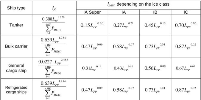
.8 fj is a correction factor to account for ship specific design elements:
.1 The power correction factor, fj, for ice-classed ships should be taken as the greater value of fj0 and fj,min as tabulated in table 1 but not greater than fj,max = 1.0.
For further information on approximate correspondence between ice classes, see HELCOM Recommendation 25/73.
Table 1: Correction factor for power f j for ice-classed ships
Ship type fj0 fj,mindepending on the ice class
IA Super IA IB IC
Tanker
nMEi i ME
PP
P L
1 ) (
920 .
308 1
. 0
30 .
15 0
.
0 LPP 0.27LPP0.21 0.45LPP0.13 0.70LPP0.06
Bulk carrier
nMEi i ME
PP
P L
1 ) (
754 .
639 1
. 0
09 .
47 0
.
0 LPP 0.58LPP0.07 0.73LPP0.04 0.87LPP0.02
General
cargo ship
nME
i i ME
PP
P L
1 ) (
483 .
0227 2
. 0
16 .
31 0
.
0 LPP 0.43LPP0.12 0.56LPP0.09 0.67LPP0.07
Refrigerated
cargo ships
nME
i i ME
PP
P L
1 ) (
754 .
639 1
. 0
09 .
47 0
.
0 LPP 0.58LPP0.07 0.73LPP0.04 0.87LPP0.02
.2 The factor fj, for shuttle tankers with propulsion redundancy should be fj = 0.77. This correction factors applies to shuttle tankers with propulsion redundancy between 80,000 and 160,000 dwt. Shuttle tankers with propulsion redundancy are tankers used for loading of crude oil from offshore installations equipped with dual-engine and
3 HELCOM Recommendation 25/7 may be found at http://www.helcom.fi.
twin-propellers need to meet the requirements for dynamic positioning and redundancy propulsion class notation.
.3 For ro-ro cargo and ro-ro passenger ships fjRoRo is calculated as follows:
13
1
pp
s s
s pp n jRoRo
L d
B B
F L f
L
; If fjRoRo > 1 then fj = 1
where the Froude number,
nL
F , is defined as:
g L F V
pp ref nL
0.5144
and the exponents
,
,
and
are defined as follows:Ship type
Exponent:
Ro-ro cargo ship 2.00 0.50 0.75 1.00 Ro-ro passenger ship 2.50 0.75 0.75 1.00
.4 The factor fj for general cargo ships is calculated as follows:
3 . 0 3 . 2
174 . 0
b
j Fn C
f
; If fj > 1 then fj = 1
Where
3 1
5144 . 0
g
Fn Vref ; If Fn > 0.6 then Fn = 0.6
and
s s pp
b L B d
C
.5 For other ship types, fj should be taken as 1.0.
.9 fw is a non-dimensional coefficient indicating the decrease of speed in representative sea conditions of wave height, wave frequency and wind speed (e.g. Beaufort Scale 6), and is determined as follows:
.1 for the attained EEDI calculated under regulations 20 and 21 of MARPOL Annex VI, fw is 1.00;
.2 when fw is calculated according to the subparagraph .2.1 or .2.2 below, the value for attained EEDI calculated by the formula in
paragraph 2 using the obtained fw should be referred to as
"attained EEDIweather";
.1 fw can be determined by conducting the ship specific simulation on its performance at representative sea conditions. The simulation methodology should be based on the Guidelines developed by the Organization4 and the method and outcome for an individual ship should be verified by the Administration or an organization recognized by the Administration; and
.2 in cases where a simulation is not conducted, fw should be taken from the "Standard fw " table/curve. A "Standard fw "
table/curve is provided in the Guidelines4 for each ship type defined in regulation 2 of MARPOL Annex VI, and expressed as a function of capacity (e.g. deadweight).
The "Standard fw " table/curve is based on data of actual speed reduction of as many existing ships as possible under the representative sea condition.
fw and attained EEDIweather, if calculated, with the representative sea conditions under which those values are determined, should be indicated in the EEDI Technical File to distinguish it from the attained EEDI calculated under regulations 20 and 21 of MARPOL Annex VI.
.10 feff(i) is the availability factor of each innovative energy efficiency technology.
feff(i) for waste energy recovery system should be one (1.0)5.
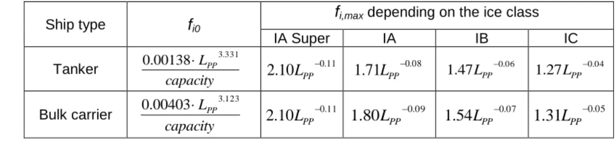
.11 fi is the capacity factor for any technical/regulatory limitation on capacity, and should be assumed to be one (1.0) if no necessity of the factor is granted
.1 The capacity correction factor, fi, for ice-classed ships should be taken as the lesser value of fi0 and fi,max as tabulated in Table 2, but not less than fi,min = 1.0. For further information on approximate correspondence between ice classes, see HELCOM Recommendation 25/76.
Table 2: Capacity correction factor fi for ice-classed ships
Ship type fi0 fi,max depending on the ice class
IA Super IA IB IC
Tanker
capacity LPP3.331 00138 .
0 0.11
10 .
2 LPP 1.71LPP0.08 1.47LPP0.06 1.27LPP0.04 Bulk carrier
capacity LPP3.123 00403
.
0 0.11
10 .
2 LPP 1.80LPP0.09 1.54LPP0.07 1.31LPP0.05
4 Refer to Interim Guidelines for the calculation of the coefficient fw for decrease in ship speed in a representative sea condition for trial use, approved by the Organization and circulated by MEPC.1/Circ.796.
5 EEDI calculation should be based on the normal seagoing condition outside Emission Control Area designated under regulation 13.6 of MARPOL ANNEX VI.
6 HELCOM Recommendation 25/7 may be found at http://www.helcom.fi.
Ship type fi0 fi,max depending on the ice class
IA Super IA IB IC
General
cargo ship capacity LPP2.625 0377
.
0 0.11
18 .
2 LPP 1.77LPP0.08 1.51LPP0.06 1.28LPP0.04 Containership
capacity LPP2.329 1033
.
0 0.11
10 .
2 LPP 1.71LPP0.08 1.47LPP0.06 1.27LPP0.04 Gas carrier
capacity LPP2.590 0474
.
0
25 .
1 2.10LPP0.12 1.60LPP0.08 1.25LPP0.04 Note: Containership capacity is defined as 70% of the DWT.
.2 fi VSE7 for ship specific voluntary structural enhancement is expressed by the following formula:
design enhanced
design reference iVSE
DWT f DWT
where:
design reference ship
design
reference lightweight
DWT
design enhanced ship
design
enhanced lightweight
DWT
For this calculation the same displacement (Δ) for reference and enhanced design should be taken.
DWT before enhancements (DWTreference design) is the deadweight prior to application of the structural enhancements. DWT after enhancements (DWTenhanced design) is the deadweight following the application of voluntary structural enhancement. A change of material (e.g. from aluminum alloy to steel) between reference design and enhanced design should not be allowed for the fi VSE
calculation. A change in grade of the same material (e.g. in steel type, grades, properties and condition) should also not be allowed.
In each case, two sets of structural plans of the ship should be submitted to the verifier for assessment. One set for the ship without voluntary structural enhancement; the other set for the same ship with voluntary structural enhancement (alternatively, one set of structural plans of the reference design with annotations of voluntary structural enhancement should also be acceptable).
Both sets of structural plans should comply with the applicable regulations for the ship type and intended trade.
.3 for bulk carriers and oil tankers, built in accordance with the Common Structural Rules (CSR) of the classification societies and assigned the class notation CSR, the following capacity correction factor fiCSR should apply:
7 Structural and/or additional class notations such as, but not limited to, "strengthened for discharge with grabs" and "strengthened bottom for loading/unloading aground", which result in a loss of deadweight of the ship, are also seen as examples of "voluntary structural enhancements".
fiCSR = 1 + (0.08 · LWTCSR / DWTCSR)
Where DWTCSR is the deadweight determined by paragraph 2.4 and LWTCSR is the light weight of the ship.
.4 for other ship types, fi should be taken as one (1.0).
.12 fc is the cubic capacity correction factor and should be assumed to be one (1.0) if no necessity of the factor is granted.
.1 for chemical tankers, as defined in regulation 1.16.1 of MARPOL Annex II, the following cubic capacity correction factor fc should apply:
fc = R -0.7 ─ 0.014, where R is less than 0.98 or
fc = 1.000, where R is 0.98 and above;
where: R is the capacity ratio of the deadweight of the ship (tonnes) as determined by paragraph 2.4 divided by the total cubic capacity of the cargo tanks of the ship (m3).
.2 for gas carriers having direct diesel driven propulsion system constructed or adapted and used for the carriage in bulk of liquefied natural gas, the following cubic capacity correction factor fcLNG should apply:
fcLNG = R -0.56
where: R is the capacity ratio of the deadweight of the ship (tonnes) as determined by paragraph 2.4 divided by the total cubic capacity of the cargo tanks of the ship (m3).
Note: This factor is applicable to LNG carriers defined as gas carriers in regulation 2.26 of MARPOL Annex VI and should not be applied to LNG carriers defined in regulation 2.38 of MARPOL Annex VI.
.3 For ro-ro passenger ships having a DWT/GT-ratio of less than 0.25, the following cubic capacity correction factor, fcRoPax, should apply:
Where DWT is the Capacity and GT is the gross tonnage in accordance with the International Convention of Tonnage Measurement of Ships 1969, annex I, regulation 3.
.13 Length between perpendiculars, Lpp, means 96% of the total length on a waterline at 85% of the least moulded depth measured from the top of the keel, or the length from the foreside of the stem to the axis of the rudder stock on that waterline, if that were greater. In ships designed with a rake
of keel the waterline on which this length is measured should be parallel to the designed waterline. Lpp should be measured in metres.
.14 fl is the factor for general cargo ships equipped with cranes and other cargo-related gear to compensate in a loss of deadweight of the ship.
fl = fcranes. fsideloader. froro
fcranes = 1 If no cranes are present.
fsideloader = 1 If no side loaders are present.
froro = 1 If no ro-ro ramp is present.
Definition of fcranes :
Capacity ach SWL
f
n
n
n n
cranes
1
11 . 32 Re
0519 . 0 1
where:
SWL = Safe Working Load, as specified by crane manufacturer in metric tonnes
Reach = Reach at which the Safe Working Load can be applied in metres
N = Number of cranes
For other cargo gear such as side loaders and ro-ro ramps, the factor should be defined as follows:
s sideloader s sideloader No
sideloader
Capacity Capacity
f
RoRo RoRo No RoRo Capacity
Capacity
f
The weight of the side loaders and ro-ro ramps should be based on a direct calculation, in analogy to the calculations as made for factor fivse.
.15 Summer load line draught, ds, is the vertical distance, in metres, from the moulded baseline at mid-length to the waterline corresponding to the summer freeboard draught to be assigned to the ship.
.16 Breadth, Bs, is the greatest moulded breadth of the ship, in metres, at or below the load line draught, ds.
.17 Volumetric displacement, ∇, in cubic metres (m3), is the volume of the moulded displacement of the ship, excluding appendages, in a ship with a metal shell, and is the volume of displacement to the outer surface of the hull in a ship with a shell of any other material, both taken at the summer load line draught, ds, as stated in the approved stability booklet/loading manual.
.18 g is the gravitational acceleration, 9.81m/s2.
APPENDIX 1
A GENERIC AND SIMPLIFIED MARINE POWER PLANT
Note 1: Mechanical recovered waste energy directly coupled to shafts need not be measured, since the effect of the technology is directly reflected in the Vref .
Note 2: In case of combined PTI/PTO, the normal operational mode at sea will determine which of these to be used in the calculation.
AUXILIARY
ENGINES BOILER CARGO HEAT
THRUSTERS
CARGO PUMPS
REEFERS CARGO GEAR
BALLAST PUMPS SWITCH BOARD
SHAFT MOTOR PPTI WASTE HEAT
RECOVERY etc.
PAEeff
MAIN ENGINE PME
SHAFT POWER PS
MAIN ENGINE PUMPS (2.5% PME)
ACCOMMODATION (250 kW) PAE
SHAFT GENERATOR PPTO
APPENDIX 2
GUIDELINES FOR THE DEVELOPMENT OF ELECTRIC POWER TABLES FOR EEDI (EPT-EEDI)
1 Introduction
This appendix contains a guideline for the document "Electric power table for EEDI" which is similar to the actual shipyards' load balance document, utilizing well defined criteria, providing standard format, clear loads definition and grouping, standard load factors, etc.
A number of new definitions (in particular the "groups") are introduced, giving an apparent greater complexity to the calculation process. However, this intermediate step to the final calculation of PAE stimulates all the parties to a deep investigation through the global figure of the auxiliary load, allowing comparisons between different ships and technologies and eventually identifying potential efficiencies improvements.
2 Auxiliary load power definition
PAE is to be calculated as indicated in paragraph 2.5.6 of the Guidelines, together with the following additional three conditions:
.1 non-emergency situations (e.g. "no fire", "no flood", "no blackout", "no partial blackout");
.2 evaluation time frame of 24 hours (to account loads with intermittent use);
and
.3 ship fully loaded with passengers and/or cargo and crew.
3 Definition of the data to be included in the electric power table for EEDI
The electric power table for EEDI calculation should contain the following data elements, as appropriate:
.1 Load's group;
.2 Load's description;
.3 Load's identification tag;
.4 Load's electric circuit Identification;
.5 Load's mechanical rated power "Pm" [kW];
.6 Load's electric motor rated output power [kW];
.7 Load's electric motor efficiency "e" [/];
.8 Load's Rated electric power "Pr" [kW];
.9 Service factor of load "kl" [/];
.10 Service factor of duty "kd" [/];
.11 Service factor of time "kt" [/];
.12 Service total factor of use "ku" [/], where ku=kl·kd·kt;
.13 Load's necessary power "Pload" [kW], where Pload=Pr·ku;
.14 Notes;
.15 Group's necessary power [kW]; and .16 Auxiliaries load's power PAE [kW].