On-line PI Self-turning based on Inertia
Identification for Permanent Magnet Synchronous Motor Servo System
Aimeng Wang,
Wenqiang Xu
Department of Electrical Engineering, North China Electric Power University ,Baoding 071003 China
Cheng-Tsung Liu, Senior member IEEE
Department of Electrical Engineering, National Sun Yat-Sen University, Kaohsiung, Taiwan
Abstract--This paper presents an effective method to improve the dynamic performance of permanent magnet synchronous motor( PMSM) servo system which can be implemented via on-line PI self-turning. The algorithm is deduced from the relationship between PI adaptive parameters and the inertia of the PMSM servo system. The proposed method is simple and easy to implement for real- time application. Simulation results show its validity and improvements in transient as well as steady –state response better than conventional fixed-gain PI in PMSM servo system.
Keywords-PI self-turning; inertia; parameter identification;
Permanent Magnet Synchronous Motor I. INTRODUCTION
It is well known that the PI parameters play a key role in PMSM servo control system to satisfy the high performance requirement [1]-[2]. It is necessary to find the appropriate PI parameters to achieve optimal and precise servo control. Since performance of the control system is decided along with the load changing: the response characteristic of the entire system become slow which lead to be in instability when the inertia is increasing, the speed will appear the phenomenon of overshoot and even shocked at the condition of inertia decreasing. It is up to date there is few report that PI parameters have the function of on-line self-turning in PMSM serve system based on inertia identification, which makes PI controller difficult to meet the high-precision control system requirements when variation error of the system caused by load is larger[3].
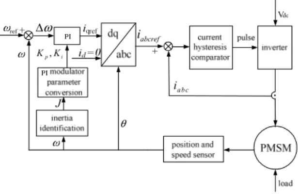
This paper presents a detailed method to realize PI parameters on-line self-turning based on inertia of the system identification. The algorithm for the relationship between PI parameters and the systems inertia is deduced from speed loop equivalent principle of the permanent magnet synchronous motor by using of speed control system theory and classical control theory. Combining with the means of look-up table, PI parameters self-turning can be implemented easily on Matlab simulation and DSP as well. The principle of control system is shown in Fig. 1.
θ
abcref
i
iabc
ω Δ
J
p, i
K K
Figure 1: Servo control system schematic diagram with PI self-turning
Servo control system schematic diagram of PMSM which takes id=0 rotor flux oriented vector control shows in Fig. 1. It is a dual closed-loop system of speed and current , which have stator current ,rotor position and speed detection. Control program structure is simple, and mainly contains PI regulator , Park transform, hysteresis control, inertia identification . The specific process is following : given speed minus factual speed is ω, then, gets given value iqref of q axis by PI regulator. Suppose id=0, so iaref、ibref、icref is known through Park transform, and they compare with three-phase feedback current ia、ib
、ic of PMSM to gets current error which go through current hysteresis comparator. Current hysteresis comparator determines switch status of inverter by the current error and emits trigger pulse which drives inverter to supply PMSM. The speed ω and position angle θ of rotor feedback to front respectively.
In order to better control permanent magnet synchronous motor, first of all, this article established its mathematical model.
II. MATHEMATICAL MODEL OF PMSM
Three-phase permanent magnet synchronous motor is the development of wound synchronous motor. Generally place three-phase symmetrical Windings in the stator.
Permanent magnet is installed in rotor instead of Electrical excitation. Stator windings and permanent magnet is Sponsor:The paper is founded by study abroad returnee scientific
research foundation of North China Electric Power University . Number :200714001
coupling through Air-gap magnetic field. As shown in Fig.
2. Define the winding current direction as the positive, Magnetic field axis which is taken place when each phase winding positive current flows is coil axis. Take A-phase winding axis of a as reference axis of Space coordinates and time vectors. Define Anti-clockwise as positive direction of the speed. ψJGf is permanent magnet flux and its direction consistent with the magnetic field axis,
i G
sis Stator current vector.
To simplify the analysis, make the following assumptions to three-phase PMSM:
(1)Y-connected for stator windings;
(2)Neglect stator winding leakage inductance;
(3)Induced electromotive force wave in phase windings is sine wave;
(4)Stator magnetic field is sinusoidal distribution, neglect high-order harmonic, not consider magnetic circuit saturation.
(5)Not consider eddy current and magnetic hysteretic loss;
(6)No damper winding in the rotor, permanent magnet has no damping effect.
A X
B
Y C
Z
S N
ψ G
fi
sG
a
b
c
Figure 2: Physical model of PMSM
a
θ
ru
di
dψ G
fβ i G
sω
ru
qi
qFigure 3: D-q rotating coordinate system
In the a-b-c coordinate system, a, b, c three-phase windings with each other are electromagnetic coupling.
Generally, use d-q coordinate transformation to achieve the purpose of decoupling and get perfect control performance. PMSM equivalent model in d-q coordinate system is shown in Fig.3 D-q coordinate system synchronous whirling with stator magnetic field, d-axis is fixed in the direction of Permanent magnet flux ψJGf , q-axis is anti-clockwise along with the speed direction, and ahead of d-axis electrical angle of 90 °.
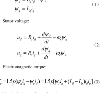
Three-phase PMSM stator flux equations in the d-q coordinate system can be expressed simply as following:
d d d f
q q q
L i L i
ψ ψ
ψ
= +
=
(1)Stator voltage:
d
d s d r q
q
q s q r d
u R i d dt u R i d
dt
ψ ω ψ ψ ω ψ
= + −
= + −
(2)
Electromagnetic torque:
1.5 ( ) 1.5 [ ( ) ]
e d q q d f q d q d q
T = p ψ i − ψ i = p ψ i + L L i i −
(3)Mechanical equations of motion:
d
m e L mJ T T B
dt
ω = − − ω
(4)Where:
u
d、 u
q ,i
d、 i
q ,L
d、 L
q,ψ
d、 ψ
q expressd-q axis component of stator voltage, current; flux and d-q axis inductance of stator winding respectively;
R
s-stator resistance;ψ
f -flux generated by rotor permanent magnet;T
e-electromagnetic torque;T
L-Load torque;ω
m -Rotormechanical angular velocity; p-the number of pole pairs; J- inertia; B-friction coefficient;
ω
r= p ω
m-rotor electrical angular velocity.By equations(1)to(4), PMSM state equation is as (5).
/ / / 0 /
/ / / / /
1.5 / 1.5 / /
/ /
d s d m q d d d d
q m d q s q f q q q q
q d
m m L
di dt R L p L L i u L
di dt p L L R L p L i u L
p J p J B J
d dt T J
ω
ω ψ
ψ ψ
ω ω
⎡ ⎤ ⎡ − ⎤⎡ ⎤ ⎡ ⎤
⎢ ⎥= −⎢ − − ⎥⎢ ⎥ ⎢+ ⎥
⎢ ⎥ ⎢ ⎥⎢ ⎥ ⎢ ⎥
⎢ ⎥ ⎢⎣− − ⎥⎦⎢ ⎥ ⎢⎣− ⎥⎦
⎣ ⎦ ⎣ ⎦
(5)
By ( 5 ) , PMSM mathematical model contains the product of mechanical angular velocity and d-q axis components of stator current. There are also products of d- q axis component of current. Therefore, the mathematical model is a multi-variable, non-linear equation of state.
d
0
i =
control is a simple control method, In the case of certain torque, require the minimum stator current , which can significantly reduce the copper consumption and improve efficiency.In the stator electromagnetic torque,in(3), order
i
d= 0
,electromagnetic torque:
T
e= 1.5 p i ψ
f q (6)From(6),electromagnetic torque is directly proportional to rotor flux
ψ
f and q-axis componenti
qof stator current when PMSM usei
d= 0
control. And because ψ and fi
qis mutual decoupling, so as long as the operation process to ensurei
d= 0
, electromagnetic torqueT
e is only controlled by q-axis component of stator current, so makes PMSM vector control is the same with the DC motor control performance [4].III. PIPARAMETERSMODELING
For AC speed control system, its electromagnetic transient process is faster than mechanical transient process. Current loop time constant is relatively small, far smaller than speed loop time constant. Therefore, regard the electromagnetic transient process has ended while designing parameters of speed loop controller. Fig. 4 shows speed loop equivalent Schematic diagram without considering the influence of friction torque. where
ω ∗
r andω
r is given speed and feedback speed respectively ,K
p andK
i is the proportional and integral coefficient of speed loop,τ
i is the time constant of current loop,p
is pole pairs of the motor,ψ
f ispermanent magnet flux, J is inertia.
The transfer function can be obtained using schematic diagram of speed loop are shown in (7) and can be expressed simply as(8).
2
3 ( )
( ) 2
( 1)
f P i
i
p K s K
G s Js s
ψ τ
= +
+
(7)2 2 2
( 1) 4 1
( ) ( 1) 8 ( 1)
s i
i i i
a s s
G s s s s s
τ τ
τ τ τ
+ +
= =
+ +
(8)Where
3 2
f i/
a = p ψ K J
andb = K
P/ K
i.In order to meet requirements of the stability and quickly response for speed Loop control, the coefficient are as:
c b = / τ
i= 4
,a = 1/ 8 τ
i2.ωr
ωr Ki
Figure 4: Schematic diagram of speed loop
Hence the relationship of PI parameters and inertia are as following:
2
,
12 3
i p
f i f i
J J
K K
P ψ τ P ψ τ
= =
(9)As p,
ψ
fτ
i are all constant, it can be seen from(9)that
K
pandK
i are linear function with inertiaJ
in PI modem. Therefore PI regulator will automatically adjust the parameters on-line when inertia is changing, which can makes the system to achieve optimal control [5].IV. INERTIA ON-LINE IDENTIFICATION FOR PMSM SERVO SYSTEM
It is known that inertia of motor and its load is close related to speed loop PI controller parameters, so if it can accurately identify inertia of the system on-line, a series of
K
P,K
i can be derived.This paper puts forward a new method of inertia on- line identification which based on motor start-up and its mechanical equation, so that the motor performance has been enhanced, while PI parameters realize the Self- adjusting, and improved the operating efficiency of the control system.
Not consider friction, motor mechanical equation is given by:
e L
J d T T dt
ω = −
(10)In (10),
J
is the system inertia, which value is the sum of motor and load inertia,T
e andT
L are torque of motor electromagnetic and the load respectively,ω
isrotor mechanical angular velocity.
Normally ,when the motor speed get a large changing, the controller will improve its output. In order to avoid damage to inverter as well as the motor, the limits on the amplitude of the available phase current is below three times of the rated current. Assuming torque current
I
q is three times of rated currentI
n that meansI
q= 3 I
nat thecondition of starting –up under the rated speed and persisted for several minutes. Based on (6), we can see that at this time the electromagnetic torque can be considered to be three times of the rated torque, that is
e
3
nT = T
,T
nis the rated torque. During the period of current is in saturation state , collecting two sampling pointst
1 andt
2, and in these two time points can be read out the speedsω ( ) t
1 andω ( ) t
2 which assumed the load torque is constant between two sampling points. According to(10), integrating at the timet
1,t
2points,(13)and (14) are available as:
1 1
0 0
2 2
0 0
( ) 3
( ) 3
t t n L
t t
t t
n L
t t
T T
d t dt
J T T
d t dt
J ω
ω
= −
= −
∫ ∫
∫ ∫
(11)
Equation(14)is derived from preceding equations,
2 1
2 1
( ) ( ) t t (3
n L)
t t T T
ω − ω = J − −
(12)Changing the largest current amplitude from three times to two times of rated current at this time limit, repeat the boot process, that is
I
q= 2 I
n,Electromagnetic torque can also be considered to be two times of the rated torque, that isT
e= 2 T
n. Re-check two sampling pointst
3 andt
4, read the speedω ( ) t
3 andω ( ) t
4 of the two time points, at this time consider the load torque and load torque same as the previous, andt
4− = − t
3t
2t
1 , get the following formula:
( )
4( )
3t
4t
3(2
n L)
t t T T
ω − ω = J − −
(13)The inertia is deduced from(15)and is(16):
2 1
2 1 4 3
[ ( ) ( )] [ ( ) ( )]
n
J T t t
t t t t
ω ω ω ω
= −
− − −
(14)From(16), we can see that load torque is not appearing on it and all the parameters in the right side equation are known. Further more, the inertia can be calculated through the different moment time and response speed, then
K
pandK
iof PI regulator can be derived by (9). Through the method of looking-up table to get appropriateK K
p,
iin practical application. In this way, The PI parameters is changing automatically since the algorithm does not rely on the object model but can identify the inertia of control system automatically [6].V. SIMULATIONRESULTS
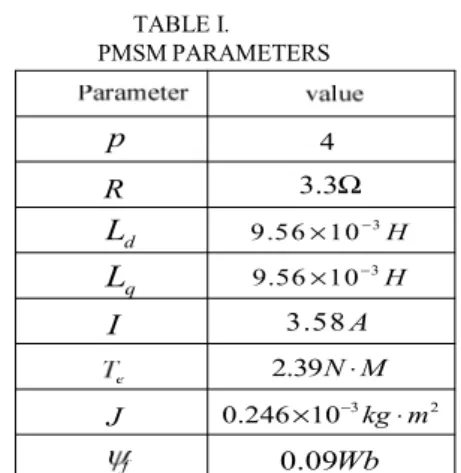
Vector control is widely used in PMSM control system, normally there are two cascade structure containing both inside current ring and outside speed ring. Fig. 1 is given its schematic diagram with PI self-turning. Inspection of Fig. 1 indicates that PI modulator can get a series of parameters coming from inertia identification at different moment time. The simulation was tested with the PMSM whose parameters are given in Table I, where p is the number of pole pairs.
Turn-on and turn-off of inverter switch is decided by current hysteresis comparator. Hysteresis modulation
TABLE I.
PMSMPARAMETERS
I Ld
Lq
J R
p 4
3.3Ω 9.56 10× −3H 9.56 10 H× −3
3.58 A 2.39N M⋅
3 2
0.246 10 kg m× − ⋅ 0.09Wb
method principle is as follows: Take A-phase for example, A phase current reference values iaref minus the actual value of A-phase current ia constitute a current bias
Δ i
, if︱⊿i︱>⊿,A-phase bridge arm of inverter is on the forward (or reverse) conduction. If ︱⊿i︱<⊿,A phase bridge arm of inverter maintain the original state of conduction. Obviously, we can effectively control the current ripple of A-phase by adjusting the comparator hysteresis bandwidth ⊿ . The other two comparator hysteresis principles are the same.
Based on Fig. 1, Simulation was completed with Matlab. PMSM parameters are as follows:
Fig. 5, Fig. 6 and Fig. 7 give the comparison of following-up performance between the different methods of PI parameters.
From the waveform graph of Fig. 5, it is obviously seen that the speed pulsation is larger with single PI parameter at the rated speed of 3000rpm, while the waveform is smooth and the overshoot is very small and it just take 27ms to reach steady state with PI self-turning method.
(a) Single PI parameter (b) PI parameter on-line identification Figure 5: Comparison for following-up speed performance at rated speed
(a) Single PI parameter (b) PI parameter online identification Figure 6: Comparison for following-up speed performance at
500rpm
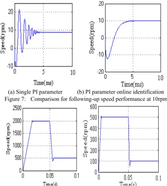
(a) Single PI parameter (b) PI parameter online identification Figure 7: Comparison for following-up speed performance at 10rpm
Figure 8: Dynamic behaviors of PMSM servo system with rated load.
at the different speed changing
Fig. 6 shows the speed can not come to 500rpm with 2 rpm difference from the definition speed for single PI parameter , while it can reach the desired speed of 500rpm with PI self-turning method; the characteristics of following-up become even better at low speed which can be seen from Fig. 7.
Fig. 8 is given the simulation results of speed variation from 2000rpm to 500 rpm, and from 500rpm into 100rpm respectively.
The simulation results indicate that the PI self-turning method can effectively improve the system following-up performance. The response of speed is speeding up significantly. The performance of system has enhanced
and it can achieve desired speed because of replacing the traditional manual adjustment. As can be seen, PI parameters on-line self-turning makes tracking performance of the system obviously optimized. The algorithm is simple and easy to be implemented in the DSP processor, which has a wide application prospect.
VI. CONCLUTION
The paper proposed PI regulator parameters self-turning strategy for permanent magnet synchronous motor control system, which can effectively improve the system dynamic performance. PI parameters can be adjusted on-line through identifying inertia of the system and combining with looking-up table. The characteristics of PMSM servo control system are improved significantly due to the PI parameters of on-line self-turning to replace the manual adjustment process.
REFERENCES
[1] Liu Zi-qian, “Hybrid Speed Control with Sliding-Mode plus Self- Tuning PI for Induction Motor Drive” Circuits and Systems, 2006.
MWSCAS apos; 06. 49th IEEE International Midwest Symposium on
Volume 1, Issue , 6-9 Aug. 2006 Page(s):500 – 504
[2] Wang Jing, Zhao Yuan-yuan “The optimization of PI controller parameters using genetic algorithm in the DC speed control system”, Intelligent Control and Automation, 2000. Proceedings of the 3rd World Congress on Volume 1, Issue , 2000 Page(s):545 - 548 vol.1
[3] Yang Ming, Gao Yang, Yu Yong, Xu Dian-guo. AC servo system PI parameters self-adjusting Based on the iterative learning control [J]. Journal of Motor and Control, 2005,9(6):588-592.
[4] liang Wenyi, “The Study of Permanent Magnet Synchronous Motor Servo Control System”[D]. ZheJiang University. China,2006.
[5] Zhang Hao-ming, SUN Yu-kun. Permanent Magnet AC speed control system parameter identification and self-tuning PI study [J].
Chinese rural water conservancy and hydropower, 2008,5:121- 123.
[6] Gao Yang, Xu Dian-guo. Two simple methods of Permanent Magnet AC (PMAC) servo system parameters self-tuning [J]. Servo System, 2005.11:16-19.