Analysis and Realization of a Novel Repetitive Controller in Active Power Filter System
Bai-Feng Chen, Jin-Wu Gong, Lan Xiong, Liang Qin, Xiao-Ming Zha, Member, IEEE
School of Electrical Engineering Wuhan University Donghu South Road, No. 8
Wuhan, China
[email protected], [email protected] Abstract -- The repetitive control has been widely used in grid
connected voltage source converters, such as uninterruptible power supplies (UPS), photovoltaic inverter (PV) and active power filter (APF). This paper introduces a new repetitive control strategy in the APF system; the proposed control strategy has a forgetting factor (FF), which could improve control system robustness. Control system stability and convergence analysis points out that control system characteristics depend on characteristic expression, which is essential for controller design. Appropriate design of this characteristic expression could make control system have good stability and fast convergence rate. Combination of industrial application, this paper presents a controller analysis and design methods, at last, simulations and experiment results demonstrate the validity of proposed repetitive control strategy.
Index Terms--repetitive control; active power filter;
forgetting factor; characteristic expression.
I. INTRODUCTION
Active power filter (APF) has been demonstrated to be a very effective mechanism to alleviate the harmonic currents due to the daily growing nonlinear loads in the power system [1]-[2]. Implementing a fast and accurate current controller is generally viewed as an important factor of design in APF applications. Most controllers with precise harmonic tracking are either overburdened by complex computational requirements or have high parametric sensitivity (sometimes both). Simple linear proportional-integral (PI) controllers have the characteristic of fast tracking speed and easy for implementation, but it also has the drawbacks: steady-state error in the stationary frame and the need to decouple phase dependence in three phase systems [3].
To overcome the shortage of the PI controller, the repetitive control, which is originated from internal-model principle of control theory [4]-[7], is put forward and widely used in wind, hydro and solar energy system; uninterruptible power supplies (UPS), photovoltaic (PV), dynamic voltage restorer (DVR), and APF systems. Repetitive controller’s transfer function is usually described as (1):
re r sTs
e 1
H =K + K
− (1) Where K and r K represent the gain coefficients of s direct feedback control and repetitive control respectively.
Repetitive control can incorporate feedback and feedforward
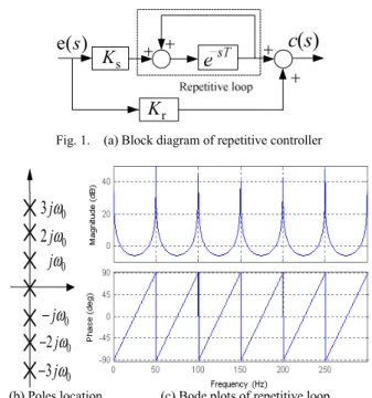
into the controller of APF and it also has the characteristics of good robustness, serf-optimizing and self-stabilizing [8]. The block diagram of repetitive controller and theoretical Bode plots of repetitive loop are shown in Fig.1 (a) and (c). And defineω0 =2πf0 =2 /π T , 0.02T = s. The Fig.1 (b) presents the poles locations of repetitive loop. All poles are on the imaginary axis.
Fig. 1 (c) shows that repetitive control has infinite gain at frequency point of all harmonics, which means the control could eliminate all harmonic signals theoretically.
While, in fact, traditional repetitive control may bring unstable problems to control system, to make controllers more realizable in practice, this paper introduces a forgetting factor (FF) Kf immediately after the delay block for introducing some damping and enhancing robustness to the control path. TheKf adds damping to all the poles by slightly shifting them to the left of the imaginary axis by an amount equal to σ > [9]-[10]. For the repetitive loop, this 0 shifting process can mathematically be expressed as (2), (3):
Ks
Kr
( ) e( )s c s
Fig. 1. (a) Block diagram of repetitive controller
×
× ×
× ×
×
jω00
2 jω 3 jω0
jω0
− 2 jω0
− 3 jω0
−
×
(b) Poles location (c) Bode plots of repetitive loop
PEDS2009
( )
( )
-sT -(s+ )T
-sT -(s+ )T
f f
e 1 e
1 e 1 e
Y s
E s K K
σ σ
σ σ
+ = = ⋅
+ − − (2)
- T
0≤Kf =eσ⋅ ≤1,s= jω (3) Influenced byK , the Bode plots in Fig. 2 (c) clearly f show that as K decreases (from 1,0.95 to 0.9), the f proposed repetitive controller’s peaks, originally of infinite magnitude, have a maximum magnitude of 1/(1−Kf)and a minimum magnitude of1/(1+Kf). The peak amplitude is reduced while the bandwidth of each peak increases, which improve the robustness with respect to frequency variations.
The forgetting factor adopted by this paper improves the robustness of repetitive control system. This paper would apply this controller in APF system, which is presented in Part II; the stability analysis and parameters design is carried out in Part III; convergence analysis and parameters design is carried out in Part IV; also simulation and experiment results demonstrate the validity of proposed control system in Part VI.
II. APF SYSTEM CONFIGURATION
The block diagram of simple shunt APF system configuration is presented in Fig.3. Control system detects harmonic current at system side. And through repetitive controlling, the PWM inverter is controlled to inject a harmonic current IAF( )s to loads side and eliminate the system side harmonic current to zero.
The closed-loop control system is given out in the Fig.4.
h( )
IL s and ISh( )s represent the harmonic current at load side and system side respectively.GAF(s) stands for the transfer function of PWM inverter and Second-order Low-
pass filter with 3000Hz cut-off frequency(ωq) and 0.707 quality factor(1/ξq), and PWM inverter model is equal to a delay loop; the switching frequency (1/TPWM ) is 10 KHz, the transfer function of GAF(s)is
2
2 2
( ) 1
0.5 1
2
q AF
PWM
q q q
G s
T s
s s
ω
ξ ω ω
= ⋅
⋅ +
+ + (4)
The interface inductor has heat loss, which could be equal as a resistance, and the transfer function of inductor is
( ) 1
sp
f
G s = sL R
+ (5) APF system parameters and controller parameters are presented in Table I.
TABLE I. APF SYSTEM PARAMETERS
System side value APF value controller value system voltage 220V
Lf 0.25mH Kr 1.5
Ls 0.001mH R 0.1
Ks 1.5
F 50Hz
Udc 1000V
Kf 0.95
III. STABILITY ANALYSIS AND PARAMETERS DESIGN A. Design of K r
When repetitive loop is not put into use, the control system should be stable just with feedback control of Kr[11], and the control system diagram is shown in Fig.5.
Nonlinear Load
Repetitive controller sh
S V
V +
is iL
LS
Lf
iAF
Inverter
c
ud
ish
Fig. 3. Block diagram of APF configuration system
Kr
Ks
+ e−sT
Kf
AF( )
G s Gsp( )s I sAF( )
Sh( ) I s
L( ) I s
AF( ) I s
+
+ −
+ +
Fig. 4. Block diagram closed-loop control system
Ks
Kr
Kf
( ) e( )s c s
Fig. 2. (a) Block diagram of proposed repetitive controller
×
××
××
×
jω00
2 jω 3jω0
jω0
− 2 jω0
− 3jω0
−
× ×
××
××
×
×
σ
(b) Poles location (c) Bode plots of proposed repetitive loop
PEDS2009
The open-loop transfer function in Fig.5 is
2 r
2 2 2
( ) ( ) 2
q s
P P q q q
G s K
T L s L T R s R s s
ω
ξ ω ω
= ⋅
⋅ + + ⋅ + + +
r AF( ) sp( ) LP( )
K G s G s G s
= ⋅ ⋅ ⋅ (6)
Bode plots in Fig.6 show control system has good stability margin whenKr =1.5. The phase margin is 52.7degree.
B. Design of Repetitive Loop
When control system is stable with feedback control ofKr, the repetitive loop could be put into use and would not change the original control system stability [11]. After repetitive loop being put into use, the block diagram of proposed control system is presented in Fig.7. A good controller should firstly ensure stability, and then provide enough harmonic rejection ability. In addition, the error convergence should be as fast as possible. The convergence rate would be discussed in part IV. For stability analysis, this paper chooses the sensitivity function and small gain theorem for the system stability analysis and parameter design [12].
The stability analysis with small gain theorem is based on sensitivity function ( )S s of close-loop control system [12].
The sensitivity function in the Fig.7 is presented in (7):
f r
( ) 1
( ) (1 )
( ) 1 (s) ( )
Sh sT
Lh AF SP
I s
S s K e
I s K G G s
= = ⋅ − ⋅ −
+ i
f s
r
1
(s) ( )
1 ( )
1 (s) ( )
sT AF SP
AF SP
K G G s
e K
K G G s
− − −
+
(7)
And define GF(s)as characteristic expression:
s f
r
(s) ( )
(s) 1 (s) ( )
AF SP
F
AF SP
K G G s
G K
K G G s
= −
+ (8)
The equal block diagram of (7) is presented in the Fig.8, which has a positive feedback loop. To guarantee asymptotic stability, a sufficient but not necessary condition is that the feedback loop should have a gain that's smaller than 1, which means the system would be stable as long asGF(s) 1< .
WhenKf = , (s)1 GF would near 1 in high frequency band and the control system would has a relative small stability margin. On another hand, the reducing ofK would bring f reduce of resonant peaks of repetitive loop for harmonics, in other words, the smaller K is, the bigger steady-state error f will be. So,K would affect the system stability in high f frequency band and decide system error in steady-state.
WhenKr =1.5,Ks =1.5, Fig. 9 presents the value of
F(s)
G for differentK . When f Kf = ,1 GF(s)almost equal to 1 in high frequency band, which means the control system has poor stability. While, when Kf =0.95,GF(s)almost equal to 0.95 and less than 1 in high frequency band, which meets stability requirement in small gain theorem. So this paper choosesKf =0.95.
f r
1
1 (s) ( )
sT
AF SP
K e K G G s
− ⋅−
+ +
+
e−sT f s
r
(s) ( )
1 (s) ( )
AF SP
AF SP
K G G s K − K G G s
+ Lh( )
I s ISh( )s
Fig. 8. Sensitivity function of control system
Fig. 9. Amplitude-frequency diagram of GF(s) Kr
Ks
+
e−sT Kf
AF( )
G s G ssp( )
Lh( ) I s
AF( ) I s
Sh( ) I s
+
+ +
+ −
Fig. 7. Block diagram of proposed control system Fig. 6. Bode plots of control system with Kr=1.5
Kr GAF( )s Gsp( )s
Lh( ) I s
AF( ) I s
Sh( ) I s
+
−
Fig. 5. Block diagram of control system with Kr
PEDS2009
IV. CONVERGENCE ANALYSIS AND DESIGN
Repetitive controller could eliminate the tracking error caused by period disturbance ISh( )s , when periodic
Sh( )
I s occurs, the controller can track the real-time dynamic error and compensate its output in next switch period. Due to the time delay block, the date processing of repetitive loop is based on period T. The convergence analysis of proposed controller is carried out in the discrete domain, which is also based on the repetitive period T (T is the fundamental cycle, which is 0.02s), and the k denotes the counting of the learning period, k=1; 2; 3 means it is the first period (T), second period (2T),third period (3T) respectively. So the repetitive control process could be described as (9) to (11):
1( ) s , 1( ) f ( )
k Sh k k
U + s =K I⋅ + s +K U s⋅ (9)
, 1( ) r , 1( )
c k Sh k
U + s =K I⋅ + s (10)
, 1( ) ( ) ( ( ) , 1( )) ( ) ( )
Sh k Lh k c k AF sp
I + s =I s − U s +U + s ⋅G s G s⋅ (11) From the equations (9) to (11), the relationship between
1( )
Uk+ s with U s and ( )k( ) ILh s could be got as (12):
s
1 f
r
(s) ( )
( ) ( ) ( )
1 (s) ( )
AF SP
k k
AF SP
K G G s
U s K U s
K G G s
+ = −
+
s
r
1 AF(s) SP( ) Lh( )
K I s
K G G s
+ + (12)
When (s)e =ek(s) , the relationship between U s , k( )
1( )
Uk− s is given by
s
f 1
r
(s) ( )
( ) ( ) ( )
1 (s) ( )
AF SP
k k
AF SP
K G G s
U s K U s
K G G s −
= −
+
s
r
1 AF(s) SP( ) Lh( )
K I s
K G G s
+ + (13)
And theΔUk+1( )s , ( )ΔU sk are defined as following:
1( ) 1( ) ( )
k k k
U + s U + s U s
Δ = − (14)
( ) ( ) 1( )
k k k
U s U s U − s
Δ = − (15)
Together with the equations (12), (13), (14) and (15), the convergence process for ΔUk+1( )s and ( )ΔU sk could be deduced in (16):
s
1 f
r
(s) ( )
( ) ( ) ( )
1 (s) ( )
AF SP
k k
AF SP
K G G s
U s K U s
K G G s
Δ + = − ⋅Δ
+
(s) ( )
F k
G U s
= ⋅ Δ (16) With (9), (10) and [(12)−Kf∗(13) /] Ks , the error convergence process could be deduced in (9).
s
, 1 f ,
r
(s) ( )
( ) ( ) ( )
1 (s) ( )
AF SP
Sh k Sh k
AF SP
K G G s
I s K I s
K G G s
+ = − ⋅
+
f
r
1 ( )
1 AF(s) SP( ) d
K I s
K G G s + −
+
f ,
r
(s) ( ) 1 ( )
1 (s) ( )
F Sh k Lh
AF SP
G I s K I s
K G G s
= ⋅ + − ⋅
+ (17)
The error convergence process in (17) indicates that the repetitive control would converge when k→ ∞ , if the characteristic expressionGF(s)served the equation whatever k is:
(s) 1
GF ∞< (18) Where G( )• ∞ means the H∞ norm of rational function, (s)G ∈RH∞n m× , which definition is:
{ }
( ) sup ( )
G G j
ω σ− ω
∞ −∞≤ ≤+∞
• = (19)
{ }
σ− • denotes biggest singular value of the complex matrix (G jω).
While, the (16) indicates that the convergence rate also depends on GF(s), and Uk+1( )s would converge to desired value fast when GF(s)is near to 1. So, although small
F(s)
G could guarantee the convergence, the fast convergence rate require GF(s)near to 1. In this paper, GF(s)is designed to near to 0.9 in wide frequency band.
Krand Kfhave been decided, only Ks could change the value of GF(s). WhenKr =1.5,Kf =0.95, Fig.11.presents the Amplitude-frequency diagram ofGF(s).GF(s)is more than 1 at low frequency band and control system has a poor stability when KS= ; while,3 GF(s)is always less than 1 and meet s the requirement for stability and convergence when )
(s
GAF Gsp(s) + + −
+ +
)
1(s
Uk+ Uk(s)
, 1( ) Uc k+ s +
Kr
Ks
e−sT Kf
Sh( ) I s
, 1( ) ISh k+ s
Lh( ) I s
AF( ) I s
Fig. 10. Block diagram of control system in discrete domain
Fig. 11. Amplitude-frequency diagram of GF(s)
PEDS2009
S 1.5
K = . In this paper, the control parameters is chosen as
r 1.5
K = ,KS=1.5,Kf =0.95.
V. SIMULATION AND EXPERIMENT RESULTS
For verifying the validity of proposed repetitive control strategy, simulations on MATLAB/simulink are carried out;
the results are shown in Fig.12 and 13. Nonlinear load are there-phase uncontrolled rectifier.
Fig.12 shows load side current has 48.5A harmonic current, and THD (total harmonic distortion) is 29.94%. APF starts working at 0.06s and has a response time less than 0.02s. The controller start working with parameterKrat 0.06s, due to time delay block, the repetitive loop starts working at 0.08s and harmonic currents was further reduced.
Fig.13 shows system side current is almost fundamental component after compensation of APF; the THD of system side current is 1.45%.
Based on the previously mentioned APF system configuration and parameters, the proposed repetitive controller is successfully realized in the industry application.
The control circuit is fully digitized and based on FPGA- ALTRA cyclone II EP2C20Q240 and DSP-TMS320F2812.
FPGA mainly performs following functions: harmonic detection; realization of repetitive control; Sinusoidal PWM and DC voltage control. TMS320F2812 mainly performs man-machine interface function, data analysis and device protection.
Fig.14 shows the steady-state results of industry application. Fig.14. (a) show the load side current and Fig.14 (b) shows the system side current after compensation.
Fig. 12. (a) Load side current of simulation
Fig. 12. (b) FFT analysis result
Fig. 13. (a) System side current of simulation
Fig. 13. (b) FFT analysis result
Fig. 14. (a) Load side current of experiment
Fig. 14. (b) System side current of experiment
VI. CONCLUSION
This paper introduces a novel repetitive control strategy in APF system. Proposed control strategy introduces a forgetting factor (FF), which could enhance the robustness of control system. Stability and convergence analysis point out system stability and convergence rate all have relationship to
PEDS2009
the characteristic expressionGF(s)—an expression contains system parameters and controller parameters. Appropriate design of GF(s)could guarantee stability requirement and get fast convergence rate. Combination with an industry application, this paper presents a way to design control parameters in APF system. At last, simulation and industry application results demonstrate the validity of design method for proposed repetitive controller.
REFERENCES
[1] IEEE PES Working Group, FACTS Applications, IEEE Press, Publ.
No.96-TP-116, 1996.
[2] J. Shlabbach, D. Blume, and T. Stephanblome, “Voltage quality in electrical power systems,” IEE power series No. 36, England, 2001.
[3] P. C. Loh, Y. Tang, F. Blaabjerg and P. Wang, “Time delay control of power converters: Mixed frame and stationary-frame variants,”
Twenty-Third Annual IEEE Applied Power Electronics Conference and Exposition, APEC 2008, pp. 1181-1187, 2008.
[4] S. Hara, Y. Yamamoto, T. Omata, and M. Nakano, "Repetitive control systems: A new type servo system for periodic exogenous signals,"
IEEE Trans. Autom. Control, vol. 33, pp. 659-668, Jul. 1988.
[5] B. A. Francis and W. M. Wonham, ”The internal model principle for linear multivariable regulators,” Appl. Math. Opt., vol. 2, pp. 170-194, 1975.
[6] D. N. Zmood, D. G. Holmes, and G. Bode, “Frequency domain analysis of three-phase linear current regulator”, IEEE Trans. Ind.
Applicat., vol 37, pp. 601-610, Mar/Apr. 2001.
[7] D. M. Brod, and D. W. Novotny, “Current control of VSI-PWM inverters”, IEEE Trans. Ind. Applicat., vol. IA-21, pp. 562-570, May 1985.
[8] X. M. Zha, Q. Tao, and J. J. Sun, “Development of iterative learning control strategy for active power filter,” IEEE CCECE'02, Winnipeg, Manitoba, vol. 1, pp. 245-250, May 2002
[9] G. Escobar, P.R. Martinez, M. Hernandez-Gomez and A.A.Valdez "A Repetitive-Based Controller for a Power Factor Precompensator". IEEE Transactions on Circuits and Systems I: Regular Papers; 54(9):1968–
1976, 2007.
[10] G. Escobar, J. Leyva-Ramos, P. R. Martínez, and A. A. Valdez, “A repetitive-based controller for the boost converter to compensate the harmonic distortion of the output voltage,” IEEE Trans. Control Syst.
Technol., vol. 13, no. 3, pp. 500–508, May 2005
[11] R. Griñó and R. Costa-Castelló, “Digital repetitive plug-in controller for odd-harmonic periodic references and disturbances,” Automatica, vol. 41, no. 1, pp. 153–157, Jan. 2005.
[12] G. F. Franklin, J. D. Powell, and A. Emami-Naeini, Feedback Control of Dynamic Systems. Reading, MA: Addison-Wesley, 1991.
PEDS2009