CONTROL CABINET
KR C2
edition2005User Manual
Connection / Periphery
Issued: 25 Jan 2005 Version: 00
长沙工控帮教育科技有限公司
eCopyright 2004 KUKA Roboter GmbH Zugspitzstrasse 140 D--86165 Augsburg
This documentation or excerpts therefrom may not be reproduced or disclosed to third parties without the express permission of the publishers.
Other functions not described in this documentation may be operable in the controller. The user has no claim to these functions, however, in the case of a replacement or service work.
We have checked the content of this documentation for conformity with the hardware and software described. Nevertheless, discrepancies
Contents
1 Connection panel . . . . 5
1.1 Safety . . . 5
1.2 Overview . . . 6
2 Connector pin allocation . . . . 7
2.1 Power supply connection. . . 7
2.2 Service socket X01. . . 7
2.3 Peripheral connector X11 . . . 8
2.4 KCP connector X19 . . . 10
2.5 Motor connector X20, axes 1 to 6 . . . 11
2.6 Optional motor connector X7 . . . 12
2.7 Data cable connector X21, axes 1 to 8 . . . 13
2.8 Interface signals X11 . . . 14
2.9 EMERGENCY STOP circuits . . . 16
2.10 Safety gate monitor . . . 19
2.11 Service jumper plug for X11 -- KR C2 . . . 20
长沙工控帮教育科技有限公司
长沙工控帮教育科技有限公司
1 Connection panel
All the connectors on the connector panel are plug--and--socket connections as defined by VDE 0627.
Accordingly, these plug--and--socket connections must not be plugged or unplugged while the controller is operational (i.e. energized).
Requirements:
G Qualified technical personnel (skilled workers) trained in the handling of systems and machines.
1.1 Safety
Before the plug--and--socket connections are plugged or unplugged, the controller and the cables concerned must be deenergized.
长沙工控帮教育科技有限公司
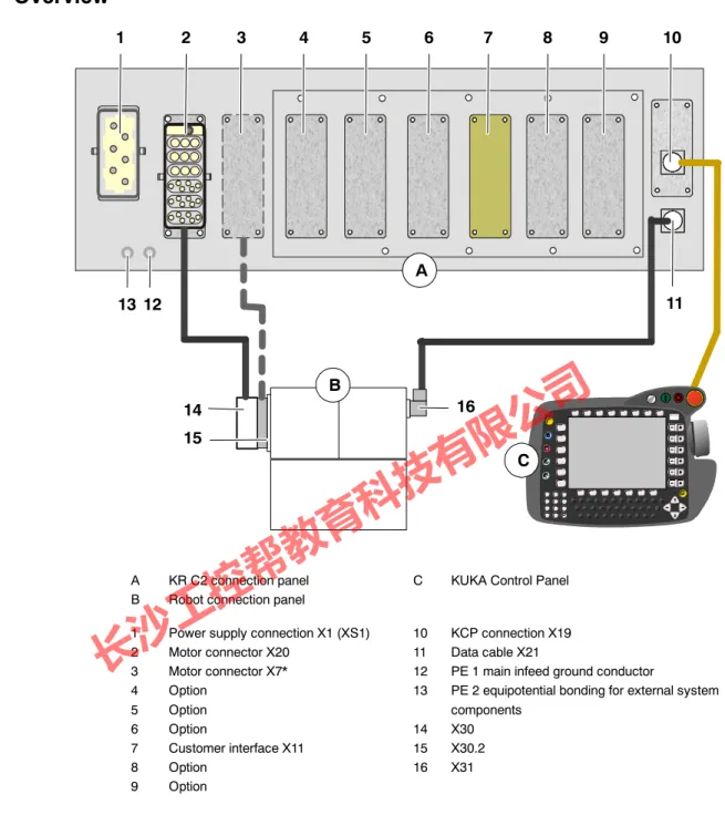
1.2 Overview
1 2 3 4 5 6 7 8 9 10
12 11 13
14 15
B
A
16 C
A KR C2 connection panel C KUKA Control Panel
B Robot connection panel
1 Power supply connection X1 (XS1) 10 KCP connection X19
2 Motor connector X20 11 Data cable X21
3 Motor connector X7* 12 PE 1 main infeed ground conductor
4 Option 13 PE 2 equipotential bonding for external system
5 Option components
6 Option 14 X30
7 Customer interface X11 15 X30.2
8 Option 16 X31
9 Option
* X7 = optional cross--sectional reinforcement for robots with high payloads
Fig. 1 Cable connections
Info
All contactor, relay and valve coils that are connected to the robot controller by the user must be equipped with suitable suppressor diodes.
(RC elements and VCR resistors are not suitable.)
长沙工控帮教育科技有限公司
2 Connector pin allocation
2 Connector pin allocation
Detailed information on connector pin allocation may be found in the corresponding “Circuit diagrams” and “Cabling description”.
2.1 Power supply connection
X1
Caution: connecting cable with toroidal cores
L1 L2 L3
Toroidal cores
* For all connections, N--conductor is only necessary for the service socket option with a 400 V power supply.
N*
1
Not connected Not connected 2
3 4 5 6
PE PE
Q1/1 Q1/2 Q1/3 X3/1 / N*
GND Q1/1 Q1/2 Q1/3 X3/1 / N*
GND
Toroidal cores
XS1
Connection examples:
X1: Harting socket installed in the connection panel XS1: Cecon connector from the cabinet
Power infeed:
3 x 400 V 50/60 Hz xx A Incoming supply only with transformer:
3 x 380 V 50/60 Hz xx A 3 x 440 V 50/60 Hz xx A 3 x 480 V 50/60 Hz xx A 3 x 575 V 50/60 Hz xx A
Fusing min. 3x25 A max. 3x32 A
2.2 Service socket X01
Optional Service socket
(Standard version for neutral conductor in the power supply!)
Supply voltage depends on the power supply used max. capacity 6 A N
L
PE F4/2
X3/1
X01
长沙工控帮教育科技有限公司
2.3 Peripheral connector X11
1 Test output A
X11
5 Test output A
7 Test output A
38 Test output A
19 Test output B
23 Test output B
4 External E--STOP channel A
22 External E--STOP channel B
6 Enabling channel A
24 Enabling channel B
8 Safeguard channel A
26 Safeguard channel B
44 Drives ON external
43 Test output B
42 Drives OFF external
41 Test output A
90 24 V DC control voltage, 6 A 36 24 V DC control voltage, 4 A
72 0 V control voltage
18 0 V control voltage
25 Test output B
39 Test output B
50 Qualifying input A
51 Qualifying input B
1 2 3 4
20 21 22 23
7 26
5 12
24 8 27
9 28
10 29 31
S afe ty m odul e E S C --C I3 boa rd
1 2 3 4
X22
X12 Optional
长沙工控帮教育科技有限公司
2 Connector pin allocation (continued)
21 Local E--STOP channel A
30 Drives ON channel B
29 Drives ON channel B
12 Drives ON channel A
11 Drives ON channel A
88 +24 V safety circuit
89 GND safety circuit
106 +24 V internal, max. 4 A
107 0 V internal
X11
46 AUTO mode
47 TEST mode
48 COM mode
2 Local E--STOP channel B
3 Local E--STOP channel B
20 Local E--STOP channel A
More detailed information on the X11 interface can be found under 2.8.
3 4
7 8
X6
9 10
6
7 35
16 17 36 18 19 37
X22
S afe ty m odul e E S C --C I3 boa rd
Peripheral interface X11 (continued)
X12
长沙工控帮教育科技有限公司
2.4 KCP connector X19
A B C D
DISPLAY+
DISPLAY-- Not connected Not connected
1 2 3 4
X805
1 2
3 4
CAN + CAN --
+24 V KCP voltage
1 2
4 3
5 6 7 8
GND
2 1
5 6
9 10
3 4
ESC In (B) X5
+24 V ESC voltage GND
ESC IN (A) ESC OUT (A) ESC OUT (B)
ESC IN (B) +VCC GND
SHIELD
ESC--CI3board
WH BU WH OG
WHBU BUWH
GN YE PK GY BN WH WHOG CAN -- OGWH
CAN + 0 V internal 24 V internal
ESC In (A) ESC Out (B) ESC Out (A)
X19
KVGA
SHIELD
SHIELD X21
长沙工控帮教育科技有限公司
2 Connector pin allocation (continued)
2.5 Motor connector X20, axes 1 to 6
Motor A1--U1 a1
a2 a3
d3
d5
PE
Motor A1--V1 Motor A1--W1
Motor A1 -- A6 brake --
Ground conductor 6.0 mm2 Motor A1 -- A6 brake + X20
4 X2
N1 3
2
Motor A2--U1 b1
b2 b3
Motor A2--V1 Motor A2--W1
4 X2
N2 3
2
Motor A3--U1 c1
c2 c3
Motor A3--V1 Motor A3--W1
4 X2
N3 3
2
Motor A4--U1 d1
d4 d6
Motor A4--V1 Motor A4--W1
4 X2
N4 3
2
Motor A5--U1 e1
e4 e6
Motor A5--V1 Motor A5--W1
4 X2
N5 3
2
Motor A6--U1 f1
f4 f6
Motor A6--V1 Motor A6--W1
4 X2
N6 3
2
F19.2 F19.4 e3
F19.6 f3
e5 f5
B--X2
长沙工控帮教育科技有限公司
2.6 Optional motor connector X7
Motor A1--U2 b1
b2 b3
a1
PE
Motor A1--V2 Motor A1--W2
Ground
Connector monitoring X7
4 X3
N1 3
2
Motor A2--U2 c1
c2 c3
Motor A2--V2 Motor A2--W2
Motor A3--U2 d1
d2 d3
Motor A3--V2 Motor A3--W2
F14.2
G1 X114 --7 a2
4 X3
N2 3
2
4 X3
N3 3
长沙工控帮教育科技有限公司
22 Connector pin allocation (continued)
2.7 Data cable connector X21, axes 1 to 8
X21
1 2 3
4 5 6 7 8 9 10 11 12 13 14 15
16 17
Not connected GND
+24 V DC
/CLKX CLKX FSR /FSR DR /DR /FSX FSX /DX DX /CLKR CLKR
Not connected Not connected Housing BK
BN BK RD BK OG BK YE BK GN BK BU
11
3 4 12 5 13 9
1 10 2 14 6
F16 X2: 12
RDC
A32
ST4
长沙工控帮教育科技有限公司
2.8 Interface signals X11
Jumpering or cross--connection of dual--channel inputs is not permitted and causes immediate disconnection of the drives!
Interface signal Pin Description Remarks
24 V control voltage +24 V internal
0 V internal
106 107
ESC power supply max. 2 A
24 V control voltage +VCC external 0 V external
88 89
In the absence of an external power supply, 24 V / 0 V must be jumpered internally
An external power supply is rec- ommended for interlinked sys- tems.
24 V control voltage +24 V
0 V
36 18
24 V control voltage for supply to external devices, max. 4 A
Optional. This control voltage is available to the customer.
Caution: max. 4 A 24 V control voltage
+24 V 0 V
90 72
24 V control voltage for supply to external devices, max. 6 A
Optional. This control voltage is available to the customer.
Caution: max. 6 A Test output A
(test signal)
1 5 7 38 41
Makes the clocked voltage avail- able for the individual interface in- puts of channel A.
Connection example: enabling switch is connected under channel A to pin 1 (TA_A) and pin 6 (A).
Test output B (test signal)
19 23 25 39 43
Makes the clocked voltage avail- able for the individual interface in- puts of channel B.
Connection example: safety gate locking mechanism is connected under channel B to pin 19 (TA_B) and pin 26 (B).
Local E--STOP Channel A Channel B
20 / 21 2 / 3
Output, floating contacts from inter- nal E--STOP max. 24 V, 600 mA
In the non--activated state, the contacts are closed
External E--STOP Channel A
Channel B
4 22
Dual--channel E--STOP input.
max. 24 V, 10 mA max. 24 V, 10 mA Enabling switch
Channel A Channel B
6 24
For connection of an external dual-- channel enabling switch with float- ing contacts max. 24 V, 10 mA
If no enabling switch is connected, pins 5 and 6 and pins 23 and 24 must be jumpered.
Only effective in TEST mode Safeguard
Channel A Channel B
8 26
For dual--channel connection of a safety gate locking mechanism max. 24 V, 10 mA
Only effective in AUTOMATIC mode
长沙工控帮教育科技有限公司
2 Connector pin allocation (continued)
Interface signal Pin Description Remarks
Drives OFF external Channel A
(single--channel)
42 A floating contact (break contact) can be connected to this input. If the contact opens, the drives are switched off max. 24 V, 10 mA
If this input is not used, pins 41/42 must be jumpered.
Drives ON external Channel B
(single--channel)
44 For connection of a floating con- tact.
Pulse > 200 ms switches drives on.
Signal must not be permanently active.
Drives ON Channel A Channel B
11 / 12 29 / 30
Floating contacts signal “Drives ON”.
(These contacts are only avail- able if an ESC--CI board is used)
Is closed if the “Drives ON” con- tactor is energized.
Operating mode groups
Automatic Test
48 / 46 48 / 47
Floating contacts of the safety relay signal the operating mode.
(These contacts are only avail- able if an ESC--CI board is used)
Test contact 48/47 is closed if Test1 or Test2 is selected on the KCP.
Automatic contact 48/46 is closed if Automatic or External is selected on the KCP.
Qualifying input Channel A Channel B
50 51
Input reserved for future functions.
(0 signal causes a category 0 STOP in all operating modes)
If these inputs are not used, pin 50 must be jumpered to test output 38, and pin 51 to test output 39.
When establishing connections, observe the technical data in your specifications!
长沙工控帮教育科技有限公司
2.9 EMERGENCY STOP circuits
Emergency Stop circuit, safeguard, and ext. enabling switch are signals that serve safety purposes and must be used in accordance with DIN EN 60204--1 and EN 775.
The following examples show how the robot EMERGENCY STOP circuit can be connected to other robots or to the periphery.
Emergency Stop circuit for one robot with periphery
107
106 88
2
3 20
21
1
19 4 0 V internal
24 V internal
Test output A
Test output B
External E--STOP channel A 89
External E--STOP channel B 22 ESC
PLC
External E--STOP in the periphery
X11
Local E--STOP channel B
Local E--STOP channel B Local E--STOP channel A
Local E--STOP channel A
长沙工控帮教育科技有限公司
2 Connector pin allocation (continued)
0 V external
E--STOP circuit for one robot with periphery and external power supply
107
106 88
2
3 20
21
1
19
4 0 V internal
24 V internal
Test output A
Test output B
External E--STOP channel A 89
22 External E--STOP channel B ESC
PLC
External E--STOP in the periphery
X11
24 V external
Local E--STOP channel B
Local E--STOP channel B Local E--STOP channel A
Local E--STOP channel A
长沙工控帮教育科技有限公司
107 0 V 72 16 106 90 36
21 Control voltage 24 V
X11
0 V 24 V
Control voltage, external
20 3 2
26 8 24 6 22 4 44 42
39 25 23 19 38 7 5 1
88 89
Local E--STOP channel A Local E--STOP channel A
Local E--STOP channel B Local E--STOP channel B
Safeguard channel B Safeguard channel A Enabling channel B Enabling channel A External E--STOP channel B External E--STOP channel A Drives ON external
Drives OFF external
24 V test output B 24 V test output B 24 V test output B 24 V test output B 24 V test output A 24 V test output A
24 V test output A 24 V test output A
24 V external VCC
0 V external GND Power supply for safety circuit
ESCboard
Safeguard
External enabling switch
ON
Drive
s OFF System
E--STOP
22 4 1 19 89 88 20 2 21 3
X11 --robot 2
EmergencyStopswitchingdevice(e.g.PNOZ10)
L-- L+
S21 Y3 S11
S22 S12
24 14
43 33
23
13
44 34
Connection example of E--STOP circuits with 2 robots connected via peripheral connector X11
长沙工控帮教育科技有限公司
2 Connector pin allocation (continued)
2.10 Safety gate monitor
X11
Peripheral connector 7 8 25 26
TestoutputA SafeguardchannelA TestoutputB SafeguardchannelB
KR C2
13 14 23 24
X1
X2 S23
S24 S12 S11 A1 (+)
A2 (---)
Safety gate monitor
e.g. PST3, manuf.: Pilz
= safety gate open
= safety gate closed
= actuated element
Ue
L+
L---
Gate position switches
Pushbutton for enable with safety gate closed
This pushbutton must be located outside the space limited by the safeguards.
Light barriers, photoelectric curtains or zone scanners must be installed in addition to or instead of safety fences. They must be connected to the overall EMERGENCY STOP system.
Irrespective of these safeguarding measures, the danger zone is to be indicated by means of paint markings on the floor. These markings must differ distinctly in form, color and style from other markings within the machine or plant in which the robot system is integrated.
长沙工控帮教育科技有限公司
2.11 Service jumper plug for X11 -- KR C2
The jumper plug is only to be used during commissioning and troubleshooting.
23 24 7 8 25 26
Safeguard
1 2
19 20 21 22 3 4
5 6
38 39
41 42 50 51
88 89 106 107 Test output B
Enabling channel B Test output A Safeguard channel A
Test output B Safeguard channel B Local E--STOP channel B
Test output B
External E--STOP channel B Local E--STOP channel A Local E--STOP channel A Local E--STOP channel B External E--STOP channel A
Test output A Enabling channel A
Test output channel A External Drives OFF
+VCC external GND external +24 V internal 0 V internal Qualifying input A
Test output B Test output A
Qualifying input B Test output A
长沙工控帮教育科技有限公司
2 Connector pin allocation (continued)
1
长沙工控帮教育科技有限公司
Connector pin allocation, 7
D
Data cable connector X21, 13
E
EMERGENCY STOP circuits, 16
I
Interface signals X11, 14
K
KCP connector X19, 10
M
Motor connector X20, 11 Motor connector X7, 12
P
Peripheral connector X11, 8
Power supply connection X1/XS1, 7
S
Safety gate monitor, 19 Service jumper plug X11, 20 Service socket X01, 7
X
X11, 8, 9