行政院國家科學委員會專題研究計畫 期末報告
晶圓基板製程中線鋸切割之模擬及改進
計 畫 類 別 : 個別型
計 畫 編 號 : NSC 100-2218-E-011-025-
執 行 期 間 : 100 年 11 月 01 日至 101 年 10 月 31 日 執 行 單 位 : 國立臺灣科技大學機械工程系
計 畫 主 持 人 : 鍾俊輝
計畫參與人員: 碩士班研究生-兼任助理人員:曾清辰 碩士班研究生-兼任助理人員:彭凱奇 碩士班研究生-兼任助理人員:李健誌 大專生-兼任助理人員:丁必陞
大專生-兼任助理人員:陳孟毅
報 告 附 件 : 出席國際會議研究心得報告及發表論文
公 開 資 訊 : 本計畫可公開查詢
中 華 民 國 101 年 12 月 10 日
中 文 摘 要 : 本計畫共包含了四個研究主題:(1)晶圓切片過程中的模態轉 變、(2)線鋸切割中固定鑽石線上的磨粒分佈影響、(3)游離 磨料線鋸切割模擬、以及(4)線鋸切割用線之專用扭轉試驗機 研發。第一項研究主題在探討從晶碇經線鋸切割至晶圓片時 的自然振動頻率以及振動模態的轉變,其結果顯示過程中晶 圓片的自然振動頻率可能會和線鋸產生共振而影響晶圓表 面。第二項研究結果顯示磨粒間距的增加會使得加工機制由 延性加工轉變為脆性加工,並同時大幅增加材料移除率,然 而,當加工機制轉為脆性加工之後,磨粒間距的增加對於材 料移除率的增加速率就會減緩,之外,磨粒的間距與單顆磨 粒受力是成線性比例的。在第三項研究中發展出了一個動態 的游離磨料線鋸加工模型,並藉由此模型了解到線速度的增 加可以同時減小弓角以及切削區受力。第四項研究為一大專 生專題實作,在此專題中製作了一個線鋸切割線材的扭轉試 驗機,此試驗機可用作日後實驗使用,而此專題並獲得 2012 模具及精密機械領域約生專題實作競賽大專組冠軍。總計此 計畫成果共包括了一篇期刊論文、二篇國際會議論文、一篇 國內會議論文、以及獲得一專題實作競賽冠軍的殊榮。
中文關鍵詞: 線鋸切割,晶圓基板製程,固定鑽石線
英 文 摘 要 : In this project, four topics are studied: (1) Modal Transition during the Wafering Process, (2) Abrasive Distribution of the Fixed Diamond Wire in Wire Sawing Process, (3) Modeling of the Slurry Wire Sawing
Process, and (4) Rotational Testing Machine for the Wire in Wire Sawing Process. The results of the first topic show the transition of the natural frequencies and the vibration modes of the wafers during wafering process. It is possible that the natural frequency of the unfinished wafer will reach those of the cutting wire, which could result in the resonance and
deteriorate the surface quality of the wafers. The results of the second topic show that the material removal rate will increase sharply when the material removal mechanism is from ductile to brittle with the increase of the abrasive interval. However, the
increase will slow down with further increase of the abrasive interval. In addition, the force on each abrasive will also increase linearly with the abrasive interval. In the third research topic, a dynamic model of slurry wire sawing process is
established. The results show that the increase of the wire will reduce both bow angle and local loadings. The fourth topic is an undergraduate
practical project. In this project, the undergraduate students build up a rotary testing machine for the wire in wire sawing process. This machine, which won the first prize in the 2012 practical project
competition of mold and precision machine, can be utilized to study the mechanical property of the wire. In this project, the publication includes one journal paper, two international conference papers, and one national conference paper. In addition, the supported undergraduate project won the first prize in the practical project competition.
英文關鍵詞: Wire Saw, Wafer Manufacturing Process, Fixed Diamond Wire
Contents
Abstract………..…..………..………P.1 中文摘要………...……….P.1 Introduction……….………...……P.1 Study Methods………...P.2 Results……….……...…P.6 Conclusions………….………...………...P.9 Acknowledgement………....…….P.10 Reference………..…………..…...…P.10
Modeling and Improvement of the Wire Sawing Process in Wafer Substrate Manufacturing
Chunhui Chung (鍾俊輝), Chin-Chen Tseng(曾清辰), Kai-Ching Peng(彭凱奇), and Mike Lee(李健誌)
NSC Project No. NSC 100-2218-E-011-025
Abstract
In this project, four topics are studied: (1) Modal Transition during the Wafering Process, (2) Abrasive Distribution of the Fixed Diamond Wire in Wire Sawing Process, (3) Modeling of the Slurry Wire Sawing Process, and (4) Rotational Testing Machine for the Wire in Wire Sawing Process. The results of the first topic show the transition of the natural frequencies and the vibration modes of the wafers during wafering process. It is possible that the natural frequency of the unfinished wafer will reach those of the cutting wire, which could result in the resonance and deteriorate the surface quality of the wafers. The results of the second topic show that the material removal rate will increase sharply when the material removal mechanism is from ductile to brittle with the increase of the abrasive interval.
However, the increase will slow down with further increase of the abrasive interval. In addition, the force on each abrasive will also increase linearly with the abrasive interval. In the third research topic, a dynamic model of slurry wire sawing process is established. The results show that the increase of the wire will reduce both bow angle and local loadings. The fourth topic is an undergraduate practical project. In this project, the undergraduate students build up a rotary testing machine for the wire in wire sawing process. This machine, which won the first prize in the 2012 practical project competition of mold and precision machine, can be utilized to study the mechanical property of the wire. In this project, the publication includes one journal paper, two international conference papers, and one national conference paper. In addition, the supported undergraduate project won the first prize in the practical project competition.
Keywords: Wire Saw, Wafer Manufacturing Process, Fixed Diamond Wire
中文摘要
本計畫共包含了四個研究主題:(1)晶圓切片過 程中的模態轉變、(2)線鋸切割中固定鑽石線上的磨 粒分佈影響、(3)游離磨料線鋸切割模擬、以及(4)線 鋸切割用線之專用扭轉試驗機研發。第一項研究主題 在探討從晶碇經線鋸切割至晶圓片時的自然振動頻
率以及振動模態的轉變,其結果顯示過程中晶圓片的 自然振動頻率可能會和線鋸產生共振而影響晶圓表 面。第二項研究結果顯示磨粒間距的增加會使得加工 機制由延性加工轉變為脆性加工,並同時大幅增加材 料移除率,然而,當加工機制轉為脆性加工之後,磨 粒間距的增加對於材料移除率的增加速率就會減緩,
之外,磨粒的間距與單顆磨粒受力是成線性比例的。
在第三項研究中發展出了一個動態的游離磨料線鋸 加工模型,並藉由此模型了解到線速度的增加可以同 時減小弓角以及切削區受力。第四項研究為一大專生 專題實作,在此專題中製作了一個線鋸切割線材的扭 轉試驗機,此試驗機可用作日後實驗使用,而此專題 並獲得2012模具及精密機械領域學生專題實作競賽 大專組冠軍。總計此計畫成果共包括了一篇期刊論文、
二篇國際會議論文、一篇國內會議論文、以及獲得一 專題實作競賽冠軍的殊榮。
關鍵詞:線鋸切割,晶圓基板製程,固定鑽石線
1. Introduction
The wafer substrate manufacturing process includes crystal growth, slicing ingot into wafers, lapping or grinding to remove subsurface damage, and polishing to achieve the requirement of surface quality. Wire saw has been utilized in the slicing process of prime wafer manufacturing over 20 years [1, 2]. It becomes the exclusive slicing tool because of the advantages such as low kerf loss and high yield. In addition, it can slice almost any sizes of ingot with the adjustment of wire span between wire guides. Therefore, it is expected that the wire saw will still be the major tool to slice 450 mm silicon ingot in the near future [3]. In addition to silicon, it is also utilized in the slicing of sapphire, SiC, and almost all kinds of materials. Wire saws can be divided into two types, slurry wire saw and fixed diamond wire saw. Slurry wire saw was introduced into the industry to replace the inner diameter saw for lager wafers[1].
During slicing, the slurry is sprayed on the wire net and brought into the slicing zone. The abrasives are suspended in the film between the wire and the ingot.
The material removal mechanism is three-body abrasion.
However, the used slurry has to be disposed, and this is not benign to the environment.
Fixed diamond wire saw emerges because of the advantages such as higher cutting rate and clearer operating environment than the slurry wire saw.
However the higher cost of the diamond wire and the poorer sliced wafer surface are the issues which impede it to substitute for the slurry wire saw [4]. The challenges of wire sawing process include the increase of the wafer size and the pursuing of thinner wafer. The semiconductor silicon wafer has been announced to increase to 450 mm in 2014[3], and thickness of solar silicon wafer is looking for a thickness of 120 m in 2020[5]. In order to slice the ingot to wafers more efficiently, the study of the slicing mechanism becomes essentially. Nevertheless, the wire is not the rigid cutting tool as those in turning or milling. The flexibility of the wire will affect the performance of the slicing process such as the loading on the abrasives and the material removal rate. A model considering the wire configuration is necessary to study the wire sawing process. In this project, both of the slurry and fixed diamond wire sawing processes are studied.
In this project, four topics are studied: (1) Modal Transition during the Wafering Process [6], (2) Abrasive Distribution of the Fixed Diamond Wire in Wire Sawing Process [7, 8], (3) Modeling of the Slurry Wire Sawing Process [9], and (4) Rotary Testing Machine for the Wire in Wire Sawing Process. These results are published in one journal paper, two international conference papers, and one national conference paper. In addition, the rotary testing machine won the first prize in the 2012 undergraduate practical project competition of mold and precision machine. In this report, the study methods of each topic are presented in Section2. Section 3 shows the research and study results. The conclusions of the project are given in Section 4.
2. Study Methods
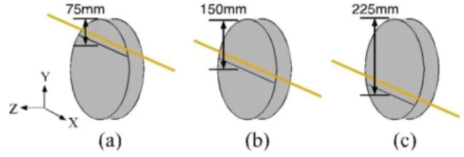
2.1 Modal Transition during the Wafering Process In this study, a slicing process of 300mm (111) silicon wafer is investigated. The Young’s modulus of (111) silicon wafer is transversely isotropic at 168.9 Gpa and the Poisson’s ratio is 0.262 for planes parallel to (111) [10]. The density of silicon is 2329 kg/m3.
Figure 1 Ingot sliced into (a) 75 mm, (b) 150 mm, and (c) 225 mm.
Three slicing conditions are considered: slicing through (a) 75 mm, (b) 150 mm, and (c) 225 mm depth, as shown in Fig. 1. The element, Shell63, was chosen for
this study. The thickness of the shell was given as 800 m. This Shell63 element has 6 degrees of freedom.
Three are translations, UX, UY, and UZ, and the other three are rotations, RotX, RotY, and RotZ. Because the unsliced part of the ingot is still fixed on the machine, the bottom of the sliced portion is set to be fixed boundary. What concerns is the deformation in the direction normal to the wafer surface. Therefore, three degrees of freedom, UX, UY, and RotZ, are set to be fixed. The meshing size was 0.01 m, and free meshing method was chosen to mesh the shell. The meshed model of 225 mm slicing depth is shown in Fig. 2. The subspace method was utilized to do modal analysis in ANSYS. The first six modes are investigated in this study.
Figure 2 Meshed model of 225 mm slicing depth.
2.2 Abrasive Distribution of the Fixed Diamond Wire in Wire Sawing Process
Brittle indentation fracture has been considered as the major material removal mechanism for the wire sawing process to slice silicon ingot into wafers [11].
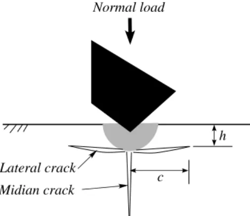
Indentation with a sharp tip will introduce the cracks inside the brittle materials, as shown in Fig. 3. The material above the lateral cracks is the one to be removed. However, there is a critical normal loading which determines whether the cracks initiates or not. The value of the critical normal loading depends on different conditions and varies from 0.003 to 0.03 N [11]. In this study, the critical normal loading is assumed to be 0.003 N. If the normal loading on an abrasive is less than 0.003 N, the plastic plowing is considered as the mechanism to remove material, and there are no cracks introduced.
Figure 3 Schematic of brittle indentation fracture during fixed abrasive wire sawing.
The penetration of the abrasive into the workpiece depends on the geometry of the abrasive, the normal loading, and the hardness of the workpiece, as shown in Fig. 4. Assume that the tip of the abrasive is a cone with tip angle of . In the model of plowing, the normal force required to penetrate the workpiece is
where is the horizontal projected area, and is the hardness of the workpiece. The tangent force required to move the abrasive forward is
where is the vertical projected area, and is the pressure to deform the workpiece plastically. This pressure is considered as the same as the hardness [12]. Therefore,
The projected areas are defined in Fig. 4.
Figure 4 Mechanism of conical abrasive wear.
Once the normal loading is less than the critical loading, the mechanism of material removal can be assumed as the abrasive plowing process [12]. In this case, the material removal rate for each abrasive can be consider as the vertical projected area, which is that
[ ] where is the material removal rate with the unit of the material removal volume per unit sliding distance. If the normal loading is over the critical value, the material above the lateral cracks will be considered as being removed, and the material removal rate will be
[ ]
where is the length of the lateral crack, and is the depth of the lateral crack, as shown in Fig. 3. They can be obtained by the following equations [13, 14].
( )
and
(
) ( )
where and . Force Analysis
The wire utilized in the wire sawing process is flexible, and the configuration of the wire, as well as the bottom of the slicing groove, is a curve rather than a straight line. In this study, the configuration of the bottom of the slicing groove is assumed as an arc with an arc angle defined by the bow angles of the wire, as shown in Fig. 5.
Figure 5 Configuration of the wire and slicing groove.
The normal loads are introduced from the wire to the abrasives, which penetrate the workpiece. The values of these loads depend on the average interval of the abrasives and the tension of the wire. In this study, only one dimensional problem is investigated, as shown in Fig. 5. Therefore, the number of abrasives can be defined according to the slicing length, , and the average interval of the diamond abrasives, , which is
when the bow angle is very small.
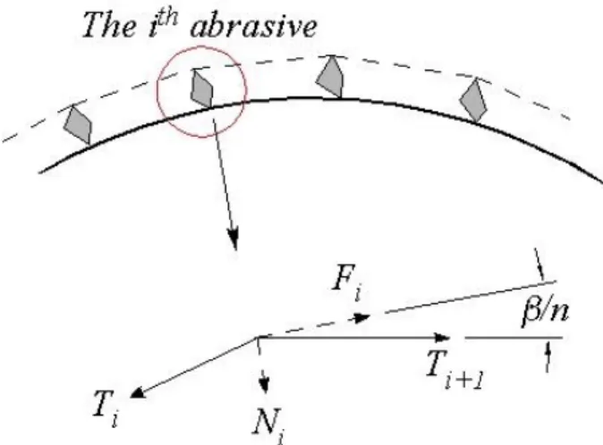
The wire is assumed to be stretched by the tension on it. The tensions can be divided into normal force and tangent force. The normal force will provide the load for the abrasives to penetrate into the workpiece, and the tangent force is the force required to overcome the strength of the workpiece to move forward. The wire tension and its fractions around an abrasive grit are shown in Fig. 6. For the ith abrasive grit, the wire tension on the left is , and the wire tension on the right is
. The normal force is
The tangent force is
Substitute equations (5) and (6) into equations (1) and (2), and solve the equations to obtain the relationship between and as follows.
( ) ( ) ( ) ( )
Therefore, the wire tension should be increased from the left to the right (the entry to the exit) in the range of slicing. The force on each abrasive can be expressed as
√ ( ) The total material removal rate will be the sum of the local material removal rate contributed by each abrasive.
Figure 6 Analysis of wire tension around an abrasive grit.
2.3 Modeling of Slurry Wire Sawing Process
In order to study the slurry wire sawing process, a numerical model was developed. In the slicing process, the conditions can be divided into semi-contact and non-contact depending on the wire tension and wire speed [11]. In order to simply the analysis, this study only considered the semi-contact situation, which means that the load is transferred from the wire into the silicon ingot through the big abrasives directly. In addition, the shear force is neglected. Therefore, only the indentation cracks introduced by the normal loads were considered as the material removal mechanism in this study.
Figure 7 Schematic of the slurry wire saw.
Figure 7 shows the schematic of the slurry wire saw globally and locally. The wire is flexible and can be deformed while in contact with the bigger abrasives. The deformed angle of the wire will introduce a load from the wire tension into the abrasive. Once this load reaches a criterion, the indentation cracks will be initiated.
According to Moller’s study, this critical loading for a SiC abrasive indenting on silicon is Pc = 0.03 N [11].
In free abrasive machining, the abrasives employed are always not uniform. There is a distribution, and only those big abrasives are considered as the active working abrasives [11] under the condition of semi-contact. The number of the abrasives depends on the working area and the slurry concentration [15], and the number of active abrasives can be a very small portion of the total abrasives. The number of active abrasives depends on the total normal loading and the mechanical properties of the cutting tool and the workpiece [16, 17]. In lapping, the workpiece and the lapping plate can be assumed perfectly flat to calculate the number of active abrasives.
However, the wire employed in the slurry wire sawing is flexible, and this assumption is not suitable. The F-400 SiC powders were considered as the working abrasives in this study. The median size of the F-400 SiC is 17.3
m. A portion of 3% of the abrasives is larger than 32
m, and 94% of the abrasives is larger than 8 m. In this study, the size of the silicon wafer was assumed to be a square of 100×100 mm2. The number of active abrasives was assumed to be 100 over the slicing length, and the sizes of the active abrasives were 32 m. Therefore, the average interval between the abrasives was 1000 m.
The wire span was assumed to be 200 mm, and the wire speed of the slurry wire saw was 10 m/s. Therefore, the active abrasiveswould rotate (10 × 106)/( × 32)=99,471 revolutions per second. If there were two edges indenting on the workpiece during one rotation of an abrasive, each abrasive particle indents about 199,000 times per second. However, because of the surface roughness and hydrodynamic effect, no all of the indentations induce cracks. The probability of effective indentations is assumed to be k. In order to obtain the probability k, the slicing parameters were assumed that
the feed rate is 5 m/s, the wire tension is 20 N, the wire speed is 10 m/s, and the cracks were initiated immediately once the load reaches 0.03 N. If the material removal is two dimensional, each effective indentation would remove the material of hc×2cc, and the following equation should be satisfied.
k×100 (abrasives) × 199,000 (indentations/s) × hc×2cc
= 5 (feedrate, m/s)×100,000 (m, length of the slicing) (9) where hc = 25.44P1/2 mm and cc = 7.50P5/8 mm are the critical cracking depth and length. Substitute into equation (9) with P = 0.03. The probability k can be obtained as k = 0.0034. Therefore, the number of the effective indentations of one abrasive is 677 per second.
Because the average interval of the abrasives is 1000 m, the number of indentation required to remove a layer of material with the depth of hc is 1000/(2cc) = 596.4.
Therefore, the time required to remove a layer of material is dt = 596.4/677= 0.88 second, which is the interval of time steps for the simulation to evaluate the normal loads on the abrasives. The parameters and values obtained in this section were considered as the benchmark for the simulation.
According to the analysis discussed in this section, a program was developed to study the wire sawing process under the conditions of wire tension T = 20 N, wire speed V =10 m/s, and feed rate f = 5 m/s. The time interval under these conditions was dt = 0.88 s.
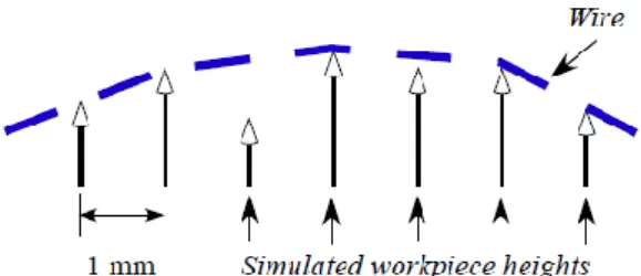
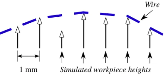
Therefore, in each time step, the height of the ingot would increase 0.88×5 = 4.4 m. The width of the ingot is divided into 100 elements, and each has the length of 1 mm, as shown in Fig. 8. In each time step, the normal force on each node was analyzed based on the deviation of the wire slopes on the node. The slopes of the wire were changed according to the different heights of the nodes, as shown in Fig. 9. The discontinuance of the slopes at the contact point provides the normal load to the workpiece through the abrasive. Two more nodes were set for the ends of the wire, and they are always at the heights of zero. Because the deviations of slopes are normally very small, the loads on the abrasives are assumed as the magnitudes of the addition of the wire tension vectors in the front and at the back of the contact points. If the normal force P ≥ 0.03 N, the height of the node will be reduced by equation (3) because of the removed material. The simulation parameters and results under these parameters were considered as the benchmark. Once the wire speed increases, the interval of time steps will decrease correspondingly because of the increase of the indentations within a unit time.
Figure 8 Nodes of the workpiece and the decreasing slopes from the left to the right of the wire.
Figure 9 Vectors of the tensions and the normal load at the contact point.
Another important consideration in the model is the variation of the slope of the wire. During slicing process, the slopes of the wire segments may change because the depths of indentation cracks reduce the heights of the nodes locally. However, because of the tension of the wire, the slopes should keep decreasing from the left of the wire to the right, as shown in Fig. 8. Note that if a node is lower than the adjacent ones, the wire should not contact with it. A loop in the program was set to check if the slopes were decreasing.
2.4 Rotary Testing Machine
In order to obtain the mechanical properties of the steel wire in wire sawing process, the tensile test and rotary test are necessary. However, the commercial testing machines are not specified for the tiny wire. The wire utilized in wire sawing process is normally from 120 to 250 m in diameter for different purposes.
Therefore, in this practical project, the undergraduate students established a small rotary testing machine for the tiny wire.They built up the structure of the machine and developed the circuit board and control algorithm by themselves. The assembly drawing and finished machine are shown in Figs. 10 and 11.
Figure 10 Assembly drawing of rotary testing machine.
Figure 11 Finished work of rotary testing machine.
3. Results
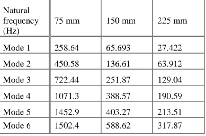
3.1 Modal Transition during the Wafering Process The results of natural frequencies of the first six modes are presented in Table 1. With the increase of sliced depth, the natural frequencies are decreased with corresponding modes. This is expected because the larger shells or longer beams normally have lower natural frequencies for the lower order modes. However, the decaying rate is not linear. For the first mode, the natural frequency is 258.64 Hz at 75 mm sliced depth, and it drops to 65.69 Hz at 150 mm and 27.422 Hz at 225 mm. Fig. 12 shows the nonlinearity of the nature frequencies of the first three modes with respect to the slicing depth.
Table 1 Simulation results of natural frequencies.
Natural frequency (Hz)
75 mm 150 mm 225 mm
Mode 1 258.64 65.693 27.422
Mode 2 450.58 136.61 63.912
Mode 3 722.44 251.87 129.04
Mode 4 1071.3 388.57 190.59
Mode 5 1452.9 403.27 213.51
Mode 6 1502.4 588.62 317.87
Figure 12 Natural frequencies of the first three modes
The mode shapes of first six modes are illustrated in Fig. 13. The first three modes have similar pattern of the corresponding mode shapes. However, the pattern of the forth mode of the 75 mm sliced model is different from the other two models. Therefore, the slicing depth actually influences the mode shapes of workpiece. It means that the vibration pattern may change during the slicing process.
Figure 13 Mode shapes of the first six modes with different sliced depths, 75 mm, 170 mm, and 225 mm.
3.2 Abrasive Distribution of the Fixed Diamond Wire in Wire Sawing Process
Table 2 Mechanical properties of the silicon in the simulation [18, 19]
Young’s Modulus
Hardness Fracture Toughness E = 127 GPa H = 10 GPa Kc = 0.7 MPa
The mechanical properties of the silicon utilized in this study are listed in Table 2. The simulation compares the average abrasive interval and the total material removal rate. In addition, the wire tension at exit is also investigated. However, the results show that the abrasive interval does not affect the wire tension at exit significantly. Figure 14 shows an example with the initial wire tension of 20 N and the wire bow angle of 5°.
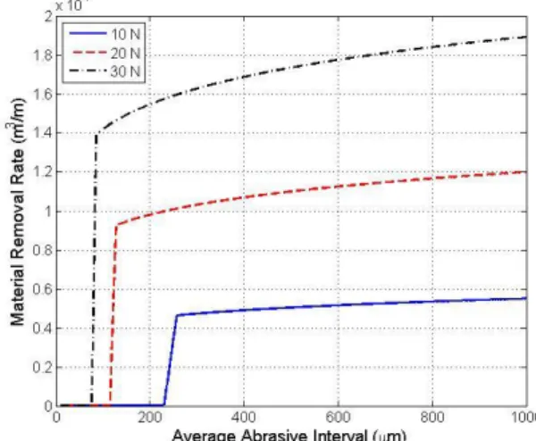
In Fig. 15, the material removal rate is compared with different bow angles. The results show that with larger bow angle, the material removal rate is higher. In addition, there is a transition of material removal rate at certain abrasive interval. The material removal rate increases dramatically when the average abrasive interval is larger than a critical value. However, this value depends on the slicing parameters such as bow angle and wire tension. This transition also presents the mechanism of material removal is from plastic deformation to brittle indentation cracking. Although the plastic deformation can eliminate the subsurface damage resulting from the cracking, the material removal rate with plastic deformation is much lower than that with brittle indentation cracking. For example, the material removal rate with abrasive interval of 115 m is ( ) with the wire tension of 20 N and the bow angle of 5°, as shown in Fig. 15. However, it is ( ) with abrasive interval of 130 m. Figure 16 shows the simulation results of material removal rate with different wire tensions at the entry. The results show that the higher wire tension will result in higher material removal rate, and there is also a transition of the material removal mechanism.
Figure 14 Wire tension at exit versus the variation of abrasive interval. The wire tension at the entry is 20 N, and the bow angle is 5°.
Figure 15 Material removal rate with wire bow angles b = 3°, 5°, and 8°. The wire tension at the entry of slicing zone is 20 N.
Figure 16 Material removal rate with wire tensions P = 10 N, 20 N, and 30 N at the entry of slicing zone. The wire bow angle is b=5°.
The force acts on the abrasive which is closest to the exit is also study compared to the average abrasive interval as shown in Figs. 17 and 18. The results show that the relationship between the force on the abrasive and the average abrasive interval is linear. However, the corresponding material removal rates in Figs. 15 and 16 approach certain steady-state limits. The diamond abrasive can come off the wire with larger force acting on it. Therefore, the abrasive interval is an important factor which affects the slicing performance manifold.
Figure 17 Force on the abrasive closest to the exit with wire bow angles b = 3°, 5°, and 8°. The wire tension at the entry of slicing zone is 20 N.
Figure 18 Force on the abrasive closest to the exit with wire tensions P = 10 N, 20 N, and 30 N at the entry of slicing zone. The wire bow angle is b=5°.
3.3 Modeling of Slurry Wire Sawing Process
Table 3 Parameters and values of the benchmark.
Wire tension
Feed rate Time interval
Element length T = 20 N f = 5 m/s dt = 0.88 s S = 1 mm
The parameters and values obtained in the previous section are summarized in Table 3. The simulated time was 17,600 s. Therefore, the total steps were 20,000.
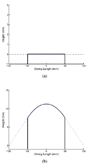
Figure 19(b) shows the simulation results when the slicing process reaches steady-state. The bow angle of the wire is about 8.6∘, which is higher than the normal operation of 1∘∼5∘. The reason is because this model only considers the indentation cracks as the material removal mechanism. Other possible mechanisms such as plowing and erosion are not included.
Figure 19 (a) Initial position and (b) steady-state simulation result with feed rate of 5 m/s, wire tension of 20 N, and wire speed of 10 m/s. the dashline is thewire.
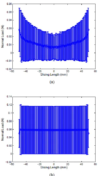
Figure 20 shows the average normal loads and their standard deviations at different nodes. The results show that while the ingot approaches the wire before the steady-state condition, the average normal loads at the edges are much higher than those at the middle. Once it reaches steady state, the average normal loads are about the same values. However, the loads at the outermost edges have obvious lower average values than the others.
In order to study the performance of the slurry wire sawing process, other conditions were investigated by changing the parameters in Table 3. Three feed rates, 2
m/s, 5 m/s, and 8 m/s were studied. In addition, another wire speed, 20 m/s, was also employed by changing the interval of time steps to 0.44 s. Therefore, the total time steps would become double compared to the wire speed of 10 m/s. The steady-state simulation results are listed in Table 4. In Table 5, another wire tension, 10 N, was studied.
Figure 20 Average normal loads and their standard deviations of (a) the first 1000 steps (t = 0 ∼ 880 s) and (b) the last 10000 steps (t = 8800 ∼ 17600 s) with feed rate of 5 m/s, wire tension of 20 N, and wire speed of 10 m/s. The dash-line is the wire.
Table 4 Simulation results of the average normal loads at the center of the workpiece and the average bow angles of the wire during t = 8800 ∼ 17600 s (the last half of the simulation). The wire tension is 20 N.
Wire speeds Feed rates
2 m/s 5 m/s 8 m/s
10 m/s 0.0156 N 2.3∘
0.0581 N 8.6∘
0.1337 N 20.8∘
20 m/s 0.0070 N 1.5∘
0.0224 N 3.4∘
0.0414 N 5.9∘
Table 5 Simulation results of the average normal loads at the center of the workpiece and the average bow angles of the wire during t = 8800 ∼ 17600 s (the last half of the simulation). The wire speed is 10 m/s.
Wire tension
Feed rates
2 m/s 5 m/s 8 m/s
10 N 0.0143 N
4.6∘
0.0502 N 15.9∘
0.0916 N 24.4∘
3.4 Rotary Testing Machine
With the machine developed in section 2.4, the brand new and used 120 m steel wires are tested. The used steel wire is the one which has been utilized in the slurry wire sawing process for over 2 hours. The testing results of maximum rotary cycles are shown in Table 6.
The results show that the average maximum rotary shear strain of used wire is reduced to half of that of the new wire.
Table 6 Results of rotary testing of 120 m steel wires.
New Wire Used Wire Average maximum rotary
cycles
90.7 cycles 45.3 cycles Average maximum shear
strain
0.427 0.213
Figure 21 Sheared section of the wire.
4. Conclusions
In this project, four topics are studied: (1) Modal Transition during the Wafering Process, (2) Abrasive Distribution of the Fixed Diamond Wire in Wire Sawing Process, (3) Modeling of the Slurry Wire Sawing Process, and (4) Rotary Testing Machine for the Wire in Wire Sawing Process. There are total on journal paper, two international conference papers, and one national conference paper published. In addition, the rotary testing machine won the first prize in the 2012 undergraduate practical project competition of mold and precision machine.
The research results show that the vibration of the wafer during slicing could be excited when it is resonant with the cutting wire. The distribution of diamond grit of the fixed diamond wire can affect the performance of fixed diamond wire sawing process with difference abrasive interval. When it reaches certain interval, the material removal mechanism will transfer form ductile to brittle, and the material removal rate will increase sharply. However, further increase of abrasive interval
will increase the loading on each abrasive and doesn’t help the increase of material removal as significantly as that at the transition. The study of the slurry wire sawing modeling shows that the increase of wire speed can reduce the bow angle and local loading during the slicing process. Nevertheless, the commercial operating speed has been reached 10 m/s. For further increase of wire speed, the strength of the wire must be considered.
The studies in the project are preliminary. They are worth to be further investigated to obtain more comprehensive understanding of the wire sawing process, such as the process parameters, vibration issues, and surface and subsurface damages of the wafers.
Acknowledgements
This work is funded by National Science Council under grant NSC-100-2218-E-011-025.
References
[1] Z. J. Pei, et al., "Grinding of silicon wafers: A review from historical perspectives,"
International Journal of Machine Tools &
Manufacture, vol. 48, pp. 1297-1307, Oct 2008.
[2] I. Kao, "Technology and Research of Slurry Wiresaw Manufacturing Systems in Wafer Slicing with Free Abrasive Machining,"
International Journal of Advanced Manufacturing Systems, vol. 7, pp. 10-23, 2004.
[3] ITRS. (2010). International Technology Roadmap for Semiconductors 2010 Update.
Available:
http://www.itrs.net/links/2010itrs/home2010.ht m
[4] D. Kray, et al., "Solar wafer slicing with loose and fixed grains," in 2006 IEEE 4th World Conference on Photovoltaic Energy Conversion, WCPEC-4, May 7, 2006 - May 12, 2006, Waikoloa, HI, United states, 2007, pp. 948-951.
[5] ITRPV, International Technology Roadmap for Photovoltaic (ITRPV.net) Results 2011, Third Edition ed. Berlin: SEMI PV Group Europe, 2012.
[6] C. Chung, "Modal Transition during the Wafering Process of 300 mm Silicon Ingot," in Proceedings of the 28th National Conference of Chinese Society of Mechanical Engineers, Taichung, Taiwan, 2011. (NSC 100-2218-E-011-025)
[7] C. Chung, "Abrasive Distribution of the Fixed Diamond Wire in Wire Sawing Process," in International Conference on Advance Manufacturing, Yilan, Taiwan, 2012. (NSC 100-2218-E-011-025)
[8] C. Chung, "Abrasive Distribution of the Fixed Diamond Wire in Wire Sawing Process,"
Advanced Materials Research, vol. 579, pp.
145-152, 2012. (NSC 100-2218-E-011-025)
[9] C. Chung, "A Preliminary Numerical Study of the Slurry Wire Sawing Process," in Proceedings of the ASME 2012 International Manufacturing Science and Engineering Conference, Notre Dame, IN, USA, 2012. (NSC 100-2218-E-011-025)
[10] J. Kim, et al., "Why Is (111) Silicon a Better Mechanical Material for MEMS?," presented at the Digest, Transducers, Munich, Germany, 2001.
[11] H. J. Moller, "Basic mechanisms and models of multi-wire sawing," Advanced Engineering Materials, vol. 6, pp. 501-513, Jul 2004.
[12] J. Williams, Engineering Tribology. New York:
Cambridge University Press, 2005.
[13] B. R. Lawn, et al., "Elastic/Plastic Indentation Damage in Ceramics: The Median Radial Crack System," Journal of the American Ceramic Society, vol. 63, pp. 574-581, 1980.
[14] D. B. Marshall, et al., "Elastic/Plastic Indentation Damage in Ceramics: The Lateral Crack System," Journal of the American Ceramic Society, vol. 65, pp. 561-566, 1982.
[15] O. Imanaka, "Lapping mechanics of glass - especialy on roughness of lapped surface,"
Annals of the CIRP, vol. 13, pp. 227-233, 1966.
[16] Y. P. Chang, et al., "An Investigation of Material Removal Mechanisms in Lapping with Grain Size Transition," Journal of Manufacturing Science and Engineering, vol.
122, pp. 413-419, 2000.
[17] R. Chauhan, et al., "Role of indentation fracture in free abrasive machining of ceramics," Wear, vol. 162-64, pp. 246-257, 1993.
[18] B. Lawn, Fracture of Brittle Solids, Second ed.
New York: Cambridge University Press, 1993.
[19] S. Bhagavat and I. Kao, "Ultra-low load multiple indentation response of materials: In purview of wiresaw slicing and other free abrasive machining (FAM) processes,"
International Journal of Machine Tools &
Manufacture, vol. 47, pp. 666-672, Mar 2007.
1
國科會補助專題研究計畫項下出席國際學術會議心得報告
日期:101 年 6 月 12 日
一、參加會議經過
本會議為美國機械工程師學會主辦之會議,並且與北美製造研究研討會(North
American Manufacturing Research Conference)及國際製程磨潤學研討會
(International Conference on Tribology in Manufacturing Processes)於同一
時間地點合辦,可說是目前北美地區最大製造相關領域之研討會。與會人士多為全
美各大學製造領域之教授和業界人士,以及來自世界各地相關研究領域之學者。發
表之論文被安排於 6 月 8 日之上午 10:30~12:00 進行報告。
計畫編號 NSC 100 - 2218 - E - 011 - 025 -
計畫名稱 晶圓基板製程中線鋸切割之模擬及改進 出國人員
姓名 鍾俊輝 服務機構
及職稱 國立臺灣科技大學助理教授 會議時間 101 年 6 月 4 日至
101 年 6 月 8 日 會議地點 美國印第安娜州聖母大學
會議名稱
(中文)國際製造科學與工程研討會
(英文)ASME International Manufacturing Science and Engineering
Conference
發表論文 題目
(中文)游離磨料線鋸切割製造之初步數值研究
(英文)A Preliminary Numerical Study of the Slurry Wire Sawing
Process 附件四
二、與會心得
此會議由於有不少美國知名學者參與,所以與會論文均有一定的水準,在此會
議中學得不少新的科技發展及知識。此外,會議中另有安排業界人士之演講及座談
會,讓大家能了解業界的走向及問題所在。這次會議主題是放在生醫製造工程上,
故有不少講座是以此主題做為演講及討論內容,以期帶動生醫製造領域的發展。
三、考察參觀活動(無是項活動者略)
四、建議
此次會議參與之台灣學者不多(所見含本人僅三位),但會議內容及國際地位皆
在水準以上,參與此會議除了發表研究成果之外,另外能結識世界頂尖之學者及提
升臺灣在國際上的可見度和名聲,故在此十分建議國內學者多參與此會議。
五、攜回資料名稱及內容
會議手冊及會議論文集光碟各一。
六、其他
會議過程中最感人的是來自臺灣的學者,美國阿拉巴馬大學的 Kevin Chou 教
授,獲得美國機械師工程學會會士之殊榮,在目前留美台灣學者日漸稀少的狀況下
實為不易。
From: [email protected]
Subject: MSEC2012-7289 - Draft Paper Accepted Date: February 17, 2012 2:54:23 PM GMT-05:00
To: [email protected] Cc: [email protected]
Reply-To: [email protected]
*** This is an auto-generated e-mail. There is no need to respond. ***
Congratulations Chunhui Chung!
The draft you have submitted to MSEC2012 has been accepted. The final version will be eligible for publication in the conference proceedings, provided all required materials and forms are submitted by the stated deadline.
You and your co-authors will receive a separate email message with instructions for completing the Electronic Copyright agreement. You will not be able to submit your final paper until all authors have signed this form.
Your paper information is as follows:
Paper Number: MSEC2012-7289
Paper Title: A Preliminary Numerical Study of the Slurry Wire Sawing Process
Please incorporate the reviewer comments and my comments into your final version. The detailed comments of the reviewers are available at the http://www.asmeconferences.org/MSEC2012 web site. Please log in as Returning Author to see these comments.
--- My Comments ---
--- End Comments ---
When you have completed your final version and all authors have signed the Electronic Copyright Agreement, please login to your MSEC2012 author account and submit it online. You will receive on-screen confirmation of your submission, as well as an e-mail confirmation.
Congratulations again and thank you for your interest and participation in MSEC2012.
______________________________________
Zhichao Li Symposium Chair
http://www.asmeconferences.org/MSEC2012
*** This is an auto-generated e-mail. There is no need to respond.***
Proceedings of the ASME 2012 International Manufacturing Science and Engineering Conference MSEC 2012 June 4-8, 2012, Notre Dame, Indiana, USA
MSEC2012-7289
A PRELIMINARY NUMERICAL STUDY OF THE SLURRY WIRE SAWING PROCESS
Chunhui Chung
Department of Mechanical Engineering National Taiwan University of Science and Technology
Taipei 106, Taiwan
Email: [email protected]
ABSTRACT
Slurry wire saw has been utilized to slice the brittle semi- conductor wafer substrates for over 20 years. However, the com- plicated slicing process limits the further studies and advances of this exclusive slicing tool for big wafers. In this study, a numeri- cal model of the slurry wire sawing process was developed based on the mechanism of brittle indentation cracks. The simulation results illustrate how the factors such as wire speed, wire tension, and feed rate of the ingot affect the slicing conditions including the bow angles of the wire and the local normal loads on both the workpiece and the wire. In addition, the results show that the steady-state condition would be reached via overshooting or non- overshooting approach based on the slicing parameters. A higher wire speed is suggested to reduce the bow angles and local loads during slicing process. However, the limitation of the wire speed depends on the material of the wire and the specification of the wire saw machine.
INTRODUCTION
With the development of semiconductor and photovoltaic technologies, wafer substrate manufacturing has become one of the most important industries in the world. Except the semi- conductor silicon wafer and solar wafer, another growing market is the sapphire wafer for light-emitting diode (LED). The wafer substrate manufacturing process includes crystal growth, slicing ingot into wafers, lapping or grinding to remove subsurface dam- ages, and polishing to achieve the requirement of surface quality.
Slicing is the process to form wafers, and wire saw has been the
major slicing tool for the wafer substrate manufacturing process since the wafer size increased to 200 mm [1]. The advantages of the wire saw are high yield and low kerf loss. Furthermore, with the adjustment of the wire span between the wire guides, wire saw is flexible to cut any sizes of ingots. According to the ITRS roadmap 2010 update [2], the size of semiconductor silicon wafer is going to expand to 450 mm in 2014, and it is expected that the wire saw machine will still be the major slicing tool. The quality of the sliced wafer would affect the efficiency and cost of the subsequent machining processes such as lapping and polish- ing. Therefore, the understanding of the wire sawing process is very essential.
Slurry wire saw has been utilized over 20 years to slice ingots into wafers. Although the fixed diamond wire saw is emerged with higher cutting rate and easier cleaning, slurry wire sawing still produces better wafer surface [3,4]. The sliced wafer surface has the defects such as surface and subsurface damages, waviness, and warp. These defects have to be removed by the subsequent flattening processes. Therefore, the fewer defects af- ter slicing, the more facile the flattening processes will be. How- ever, wire sawing of wafer substrate is a complicated process.
Research has been studied on the thermal effect [5], elasto- hydrodynamics [6, 7], brittle indentation fracture [8, 9], crystal orientation [10], vibration [11, 12], etc. Some of the formation of the defects can be explained by these research results, such as the thermal expansion for warp. Some of them, such as wavi- ness, are still not well studied, and there is no general agreement with the mechanisms.
Because of the tiny cutting zone and dirty surroundings, it
1 Copyright c 2012 by ASME
h
c Normal load
Lateral crack Midian crack
FIGURE 1. INDENTATION CRACKS INTRODUCED BY ABRASIVE INDENTATION ON THE BRITTLE WORKPIECE.
is difficult to observe the details of the slicing process. The steel wire utilized in slicing is about 120 to 140µm in diameter cur- rently [13], and the SiC slurry is opaque. For brittle material, the material removal mechanism is considered as indentation crack- ing [8, 9]. The material removal happens locally. However, the overall slicing performance is a combination of these local ma- chining behaviors. The flexible wire may changes its configura- tion during the slicing process due to these indentation cracks. In order to study how the wire changes its configuration and the lo- cal loads on the workpiece and the wire, a preliminary numerical study was conducted and is presented in this paper.
REVIEW OF THE MACHINING MECHANISM OF BRIT- TLE MATERIALS
In the free abrasive machining of brittle materials, the ma- chining mechanisms can be divided into four types: two-body brittle machining, two-body ductile machining, three-body brit- tle machining, and three-body ductile machining [14]. Although the ductile-regime machining of brittle material is attractive for its advantage of the limitation of subsurface damages, it re- quires precise control and is still not feasible for global planariza- tion [15]. Therefore, the mechanism of indentation crack is still considered as the main reason of the material removal in wire sawing and lapping processes [8, 9, 14].
Indentation with a sharp tip will introduce the cracks inside the brittle material. The cracks are divided into the radial, me- dian, and lateral cracks [16–18]. The lateral cracks are consid- ered to contribute to the material removal in the machining pro- cess. However, the radial and median cracks leave the surface and subsurface damages after machining. Figure 1 shows a sys- tem of brittle indentation cracks.
In Fig. 1, c is the length of lateral crack, and h is the depth.
The material above the lateral cracks is considered as the re- moved chips. Therefore, the volume of the removed material in a
TABLE 1. PROPERTIES OF THE SILICON UTILIZED IN THE MODEL.
Young’s modulus Hardness Fracture toughness E= 127 GPa H= 10 GPa KC= 0.7 MPa
single indentation isπc2h [14, 19]. In order to initiate the cracks, a critical normal load is required. When the normal load on the abrasive is larger than the critical one, a chip will be produced as removed material. An experiment done by M¨oller showed that the critical normal load is 0.03 N for a SiC abrasive indenting on the silicon surface [9].
The lengths of the cracks with normal loading, P, are rela- tive to the mechanical properties of the brittle workpiece as fol- lows [16, 17].
h= (cotψ)1/3E1/2
H P1/2 (1)
and
c= ζL1/2 A1/4
!
(cotψ)5/12 E3/8 KC1/2H1/2
P5/8 (2)
where E is the Young’s modulus, H is the hardness, KC is the fracture toughness of the brittle workpiece,ψ is the half angle of the indenting tip,ζL= 25 × 10−3, and A= 3/4. The SiC abrasives are assumed as rigid bodies and have the edge angle of 2ψ= 140◦[20, 21]. The properties of silicon utilized in this study are listed in Table 1. Substitute these parameters into equa- tion (1) and (2). The relationship between the loading and the cracks can be obtained as follows:
h= 25.44P1/2µm (3)
and
c= 7.50P5/8µm (4)
where the unit of P is newton (N). With the critical normal load- ing Pc= 0.03 N, the critical cracking lengths are hc= 4.406µm and cc= 0.838µm.
NUMERICAL MODELING OF WIRE SAWING PROCESS In order to study the slurry wire sawing process, a numerical model was developed. In the slicing process, the conditions can
2 Copyright c 2012 by ASME