行政院國家科學委員會專題研究計畫 成果報告
高效能被動式超高頻無線射頻辨識系統設計與研究 研究成果報告(精簡版)
計 畫 類 別 : 個別型
計 畫 編 號 : NSC 96-2221-E-011-017-
執 行 期 間 : 96 年 08 月 01 日至 97 年 07 月 31 日 執 行 單 位 : 國立臺灣科技大學電機工程系
計 畫 主 持 人 : 劉馨勤
計畫參與人員: 碩士班研究生-兼任助理人員:花盟昌 碩士班研究生-兼任助理人員:林旺旗 博士班研究生-兼任助理人員:方偉力
報 告 附 件 : 出席國際會議研究心得報告及發表論文
處 理 方 式 : 本計畫涉及專利或其他智慧財產權,2 年後可公開查詢
中 華 民 國 97 年 10 月 30 日
行政院國家科學委員會補助專題研究計畫 ■ 成 果 報 告
□期中進度報告 高效能被動式超高頻無線射頻辨識系統設計與研究
計畫類別: ■ 個別型計畫 □ 整合型計畫 計畫編號:NSC 96-2221-E-011-017-
執行期間: 96 年 8 月 1 日至 97 年 7 月 31 日
計畫主持人:劉馨勤 共同主持人:
計畫參與人員: 方偉力 台灣科技大學電機工程所 花盟昌 台灣科技大學電機工程所 林旺旗 台灣科技大學電機工程所
成果報告類型(依經費核定清單規定繳交): ■ 精簡報告 □完整報告
本成果報告包括以下應繳交之附件:
■ 赴國外出差或研習心得報告一份
□赴大陸地區出差或研習心得報告一份
□出席國際學術會議心得報告及發表之論文各一份
□國際合作研究計畫國外研究報告書一份
處理方式:除產學合作研究計畫、提升產業技術及人才培育研究計畫、
列管計畫及下列情形者外,得立即公開查詢
■ 涉及專利或其他智慧財產權,□一年 ■ 二年後可公開查詢
執行單位:台灣科技大學
附件一
I
一、 中文摘要及關鍵詞
最近射頻辨識(RFID)系統由於其廣泛的應用潛力受到了許多注意。由於其標籤成本 低、體積小、而且感測距離長,超高頻被動式射頻辨識系統特別受到 EPCglobal 組織的提 倡。特別值得注意的是 2005 年 EPCglobal 發佈了「Gen2」超高頻被動式射頻辨識系統規 格,其規格也於 2006 年被 ISO 所採納。
由於 Gen2 標籤從 Gen2 射頻辨識讀取器發射的連續波取得它的電源,並以此連續波作 為它的調變反向散射信號的載波,因此其可讀取範圍受到高傳播路徑損失的限制。而除自 由空間衰減之外,多重路徑衰落也經常導致讀取問題。經鏈接預算分析證明,標籤接收的 電力是決定讀取距離的因素。而因為被動式標籤沒有外部電源不能運作,所以標籤電源問 題是被動式射頻辨識系統中一個不可避免的問題。此外,標籤衝突問題是另一個影響標籤 識別的正確性及效率的因素。再者,在 Gen2 標準之「密集讀取器模式」中存在的讀取器 衝突問題,也可能嚴重地降低系統效能。目前已有一些研究使用不同的方法來解決這些問 題,然而尚未有研究將這些問題做一個整體的考量。
在本三年期計劃中,我們提出一個具智慧型天線讀取器的高性能被動式射頻辨識系 統。此系統能有效地解決標籤電源問題、標籤衝突問題以及讀取器衝突問題。我們將使用 空間差異性技術改善標籤電源問題、分碼多重擷取技術搭配空間區分多重擷取技術避免標 籤衝突問題、及結合適應性波束合成與跨階層技術防止讀取器衝突問題。除理論分析之 外,我們計畫使用軟體無線電架構,實現一個智慧型天線讀取器,以實際驗證計劃所提出 的方法。本報告為第一年計畫之成果報告。
關鍵詞:射頻辨識、智慧型天線、衝突防止、軟體無線電、分碼多重擷取、空間區分多重擷取、
跨階層技術
II
二、 英文摘要及關鍵詞
The radio frequency identification (RFID) systems have recently received extensive attention due to its potential in pervasive applications. Owing to the low cost, small size, long accessible range tags, the UHF passive RFID system is especially promoted by EPCglobal. The
“Gen2” specification for UHF passive RFID system released by EPCglobal in 2005, which has also been adopted by ISO in 2006, is extremely noteworthy.
Because a Gen2 tag derives its power from the continuous waves (CW) emitted by a Gen2 RFID reader and uses the CW as the carrier of its modulated backscatter signals, the readable range is hence limited due to the large propagation loss. Besides the free space attenuation, the multipath fading effect can often result in readability problems. The link budget analysis validates that the readable distance is determined by the power received by a tag. Since a passive tag cannot operate without external power source, the tag power problem is an inevitable problem in a passive RFID system. Moreover, the tag collision problem is another factor that affects the correctness and efficiency of tag identification. In addition, there exists a reader collision problem in the “dense reader mode” specified in Gen2, which can also severely degrade the system performance.
There are a few researches using various approaches to alleviate these problems. However, none of them consider these problems as a whole.
In this 3-year project, we propose a high performance passive RFID system with smart antenna readers, which can effectively mitigate the tag power problem, the tag collision problem, and the reader collision problem. We will use space diversity technique to alleviate the tag power problem, CDMA+SDMA techniques to avoid the tag collisions, and the adaptive beamforming incorporating with cross layer techniques to prevent the reader collision problem.
In addition to theoretical analysis, we intend to implement a smart antenna reader using software defined radio architecture to verify the proposed scheme empirically. This report presents the first year research outcome of this project.
Keywords: RFID, Smart Antenna, Anti-collision, Software Defined Radio, CDMA, SDMA, cross layer.
1
三、 計畫緣由與目的:
射頻辨識(RFID),隨著技術進步及廣泛的應用,近年來受到很多的矚目,並已進行 實際運用。如同許多其他先進通訊技術,射頻辨識技術亦歷經長期研究,而於近年蓬勃發 展。射頻辨識系統依其操作頻段,可略區分為以下不同類別並依其特性各有不同應用;低 頻射頻辨識系統(LF RFID)(125 KHz 到 134.2 KHz), 高頻射頻辨識系統(HF RFID) (13.56 MHz), 超高頻射頻辨識系統(UHF RFID) (860 MHz 到 960 MHz),及微波 RFID (2.45 GHz) 等。
射頻辨識系統通常由標籤(tag or transponder)及讀取器(reader or interrogator)
所組成。每個標籤至少具有一顆晶片及天線,其功能為儲存資料、接收讀取器指令(reader command)及發射回應訊號。而依照標籤之電源供應,又可區分為主動式標籤(active tag)、半主動式標籤(semi-active tag)、被動式標籤(passive tag)等類別。其中被 動式標籤因不需電池,所以有體積較小、價格便宜、不需維護、及使用壽命較長等優點,
因此特別受到重視。目前高頻被動射頻辨識標籤(HF passive RFID tag)已被廣泛使用於 悠遊卡、晶片信用卡等。而超高頻被動射頻辨識標籤(UHF passive RFID tag),因為讀取 距離較低頻被動射頻辨識標籤遠,因此適用於供應鍊(supply chain)管理、車輛管制、
及室內定位等應用,其他可能應用亦隨著該技術發展而日新月異。目前高頻被動射頻辨識 標籤發展及應用已臻成熟;然而超高頻被動射頻辨識系統,因全球化標準之訂定[1, 2]
較晚,且其多樣性功能及應用有可能於技術成熟後取代低頻被動射頻辨識系統,而吸引了 許多研究者的投入。
因超高頻被動射頻辨識標籤(以下簡稱標籤)不具電池,必須仰賴其天線之感應 電流以提供其晶片操作電力。因此超高頻被動射頻辨識系統之讀取器(以下簡稱讀取 器),除負責發射讀取器指令及接收標籤之回應外,同時必須發射連續波以提供標籤之 操作電力。
標籤除汲取讀取器所發射之連續波作為電源之外,並利用它作為其回應之反向散 射信號(backscattered signal)載波。囿於電力限制,目前標籤之調變信號多使用振幅 位移鍵(Amplitude Shift Keying, ASK)調變、二位元相位位移鍵(Binary Phase Shift Keying, BPSK)調變等調變訊號[3, 4]。同時因標籤無法進行載波感測多重擷取(Carrier Sense Multiple Access, CSMA),因此目前被動式標籤多使用較簡易之防衝突演算法
(Anti-collision Algorithm),如二元樹演算法(Binary Tree Algorithm)及時槽阿羅哈
(Slotted ALOHA,S-ALOHA)演算法等[5]。為提升標籤之辨識率,於[1]中,FM0 碼 及 Miller 碼被使用來降低標籤反向散射信號之接收位元錯誤率(BER)[3, 6]。目前 針對標籤方面已有許多天線設計,及降低晶片之耗電量之相關研究[7, 10-19]。然而,
囿於有限、不連續且不穩定之電源限制,被動式標籤無法進行複雜運算,因此對於通 訊品質之改進相當有限。反觀讀取器則無此方面問題,因此,許多複雜先進之通訊技 術較易由讀取器端實現,並藉此改善射頻辨識系統之通訊品質。本計劃亦希望能藉由 研製高性能讀取器,來解決目前超高頻被動式射頻辨識系統所遭遇之問題。
經由系統效能評估之相關文獻[7-10]得知,目前射頻辨識系統所遭遇主要問題可 分為以下數項:標籤電源問題(或讀取距離問題)、標籤衝突(tag collision)問題、及 讀取器衝突(reader collision)問題等。因為被動式標籤本身並無電池,必須仰賴讀取
2
器提供其電源,使得標籤電源問題成為系統能否運作之主要關鍵。於[8]之鏈結預算
(link budget)分析,及市售標籤規範[11]中顯示,目前標籤值最小電源需求約為-10dBm 上 下 。 在 [10] 中 指 出 , 讀 取 器 與 標 籤 通 訊 的 限 制 在 於 標 籤 之 晶 片 靈 敏 度 ( chip sensitivity),亦即所需最小有效電源(minimum effective power),遠低於讀取器之接收 靈敏度;因此限制了被動式標籤之讀取距離。要解決標籤電源問題,可分別由標籤端 及讀取器方面分別進行。在標籤方面,晶片的改良可提高其靈敏度;此外增加其天線 之增益,改變其天線之極化,及改善晶片與天線之阻抗匹配,皆能有效改善此項問題 [4]。在讀取器方面,增加讀取器發射功率及其天線之指向性,是直接有效的辦法。然 而,囿於法規之最大有效等向輻射功率(EIRP) 限制,無限制的增加其發射功率的方 案,並不可行。
對於發射功率在行進路徑上的衰減,許多文獻皆以自由空間路徑衰減(free space path loss)之 Friis 公式,來計算讀取器發射功率與標籤接收功率之間的關係,因此認為 標籤所接受之功率,與讀取器與標籤之間的距離平方成反比或類似關係(由環境及介 質決定)。然而在實際應用中,考慮多重路徑(multipath)之影響,實際標籤接收功率,
還要考慮衰落通道(fading channel)的問題。於[9]之量測及模擬顯示,多重路徑衰落 通道的確影響了標籤之接收功率。此項結果也與申請人所完成的研究相符[12]。在[9]
中之量測,同時顯示使用兩支不同位置的發射天線(於 953MHz 附近頻率,相隔 11cm),
所產生之空間差異性(space diversity),能有效舒緩衰落問題。目前已有部分新型讀取 器[13]採用多支發射天線來解決該項問題。而申請人亦於[14, 15]中,提出一種新型 分離式讀取器設計,以解決此項問題。
另一個射頻辨識系統所遭遇的問題為標籤衝突問題;一個讀取器所涵蓋的範圍中 常同時存在多個標籤。對同一讀取器指令,同時可能有多個標籤回應,因此造成了標 籤 衝 突 問 題 。 當 多 個 標 籤 同 時 回 應 時 , 其 回 應 訊 號 可 能 互 相 干 擾 ( tag-to-tag interference),因而導致讀取器無法辨識或辨識錯誤;或辨識其中之一,而忽略了其它 的標籤,導致標籤遺失(tag missing/lost)問題。目前解決標籤衝突問題,已有相當多 的研究。其中[5]對現行射頻辨識系統標準中的標籤防衝突演算法,及讀取器防衝突演 算法作了詳細的整理;一般而言,於射頻辨識系統中,阿羅哈類演算法效率優於樹狀 結構類演算法。以目前效能最好的 Gen2 標準[1]為例,規範訂定的正是一種動態訊框 時槽阿羅哈(adaptive framed slotted ALOHA)演算法,稱之為Q演算法(Q-algorithm)。
於[16]中,申請人也對此演算法,藉由標籤數目估測結合連續衝突/閒置時槽偵測(burst collision/idle slot detection),提出效能改進辦法。該演算法效能,有賴於正確標籤數目 估測。最近,於[17]中,則提出另一種標籤標籤數目估測方法;但其缺點為複雜度甚 高,且當標籤數目不多時,該方法未必實用。綜觀現有之標籤防衝突演算法,皆為分 時多重擷取(Time Division Multiple Access, TDMA)方式,使得其性能受到侷限。因此,
若要能大幅提升其系統效能,勢必要如同其他先進通訊系統,結合其他不同多重擷取 方法。
於[18, 19]研究中分別提出以分碼多重擷取(Code Division Multiple Access, CDMA)技術,結合分時多重擷取技術,以提升標籤之讀取效能。在[20]研究中,則 首度提出利用智慧型天線來解決標籤衝突問題。此研究探討以多重輸入多重輸出
(Multiple Input Multiple Output, MIMO),及適應性波束合成(adaptive beamforming)
技術,來提昇系統效能。不過,[20]之研究僅以過於簡化之自由度(degree of freedom,
3
DOF)增加觀念,來探討並模擬標籤防衝突問題,無法確實的估測實際系統效能。
另一方面,在被動式射頻辨識系統實際應用時,勢必有多部讀取器同時在同一環 境中使用。因此在[1]中特別將密集讀取器模式(dense reader mode)列入規範。研究 顯 示 , 當 多 部 讀 取 器 同 時 運 行 時 會 造 成 兩 種 問 題 , 分 別 為 , 讀 取 器 與 標 籤 干 擾
(reader-to-tag interference)問題,及讀取器間衝突(reader collision)問題。目前讀取 器與標籤干擾問題,已於[1]中,因標籤規範改進、及密集讀取器模式制定而受到改善。
然而於密集讀取器模式中,仍存在不同讀取器於相同覆蓋範圍,同時傳送讀取器指令,
造成標籤無法識別讀取器指令之讀取器干擾問題;或當讀取器跳頻(frequency hopping)
落入同頻道所造成的同通道干擾(Co-Channel Interference,CCI)。
綜合以上所述,可以得知標籤電源問題、標籤衝突問題、及讀取器衝突問題仍為 目前射頻辨識系統研究之主要方向。鑒於標籤之低功能性(low functionality),解決這 些問題的方式,必須考慮從讀取器端著手。其中[9] 提出以多支發射天線產生之空間 差異性,來解決多重路徑干擾所造成的標籤電源問題。在[20]中則提出利用智慧型天 線(包括多重輸入多重輸出及適應性波束合成)來解決標籤衝突問題,但是其分析及 模擬過於簡化。除此之外,在提升標籤讀取效能方面,於[18, 19]提出結合分碼多重 擷取技術的方法,應可大幅提升讀取效率,但於文獻中並未考慮標籤之耗電限制問題。
於讀取器衝突問題方面,大多著重於降低讀取器之間的相互干擾,及減少讀取器之發 射功率。雖然目前尚未有文獻使用智慧型天線來解決讀取器衝突問題,但智慧型天線 於降低無線通訊干擾,及有效減少發射功率的成效已被証實。因此,智慧型天線之適 應性波束合成,及其特有的空間區分多重擷取(space division multiple access, SDMA)
技術,相信亦可有助於解決讀取器衝突問題及標籤衝突問題。因此,本計劃希望研製 具智慧型天線之高效能讀取器,搭配低複雜度低耗電性之分碼多重擷取射頻辨識標籤
(CDMA-RFID tag)設計,以提升超高頻被動式射頻辨識系統效能。並且因為超高頻被 動式射頻辨識系統為一新興技術,目前國內尚缺乏該項技術人才及其中關鍵技術。本 計劃也提出使用軟體無線電技術實現智慧型天線讀取器的目標,以實際了解開發讀取 器之關鍵問題,並可用以驗證研究所提出之創新通訊方法與協定。
本計劃為三年期之研究計畫,計畫的目標為建立一個高效能的超高頻被動式射頻 辨識系統。於計劃中,我們不著重於標籤的開發,而全力投入高效能讀取器之設計與 系統規劃。我們已於第一年開發完整系統模擬,並探究使用 CDMA 技術來解決標籤衝 突問題之可能性。同時,我們並使用軟體無線電技術實現一個符合實驗需求之讀取器。
四、 研究方法:
由文獻研究可以得知,目前超高頻被動式射頻辨識系統所遭遇之問題主要為:標籤電 源問題、標籤衝突問題、及讀取器衝突問題。由於被動式射頻辨識標籤無法進行複雜運算,
所以我們嘗試設計高效能讀取器,以解決以上三項問題。然而,要能確切實際的了解這三 項問題,除了進行實地實驗之外,建立一個完整的系統模擬,更是一個有效的驗證方法。
此一完整系統模擬,更可對本計劃之後續研究,進行可靠而有效的評估。
在此系統模擬中,如圖 1所示,我們將以讀取器、通道模擬、及標籤模擬等三部分,
分別進行。
T r a n s m it te r f o r R - > T lin k R e c e iv e r f o r T - > R lin k
M u lt ip a t h f a d in g
c h a n n e l T a g
T a g
T a g M u lt ip a t h f a d in g
c h a n n e l
M u lt ip a t h f a d in g c h a n n e l
R - > T L in k
T - > R L in k R - > T - > R L in k R e a d e r
圖 1 RFID 系統模擬示意圖
由於本系統牽涉射頻傳播(RF propagation)、微波電路、及基頻處理等部份。目前 尚未有單一模擬軟體能簡單有效的進行此類模擬。就射頻通道模擬及微波電路模擬而言,
以 Agilent 之 ADS(Advanced Design System)模擬軟體較為擅長;而基頻處理及演算法 運算方面,則以 Mathworks 之 Simulink 模擬軟體較佔優勢。於此計劃中,我們結合兩套 模擬軟體的優點來完成系統模擬。
鑒於目前標籤衝突問題的解決,大多使用 TDMA 方法,無論使用樹狀搜尋或時槽阿羅 哈演算法,其效能提升都相當有限。如欲大幅提升標籤讀取效能,勢必要引入其他多重接 取方法。於本計劃中,我們在第一年,嘗試使用 CDMA 技術,配合先前研究的改良式時槽 阿羅哈演算法[16],來提升標籤讀取效率。
於被動式射頻辨識系統,除模擬外,實驗驗證才能真正檢視其成果。在第一年,我們 先具體實現單支天線的讀取器。目前許多無線收發機的設計,多採用軟體無線電架構,部 分新型讀取器亦採用軟體無線電架構[13],因此,我們也使用該架構來縮短開發時程。
五、 結果與討論
第一年計劃中規畫了三項主要工作:完整系統模擬、使用 CDMA 技術解決標籤衝突問 題、及使用軟體無線電技術實現符合實驗需求之讀取器。以下就各項工作分別報告執行進 度與成果。
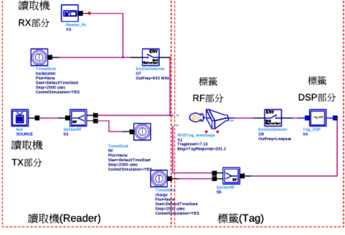
1. 完整系統模擬:目前已利用Agilent ADS軟體結合Matlab模組,完成Gen2 RFID讀 取機及被動式標籤之系統模擬(如圖 2所示),可用以模擬讀取機指令及標籤反射 訊號(如圖 3 所示)。
4
EnvOutSelector O9 OutFreq=Lowpass EnvOutSelector
O7 OutFreq=915 MHz
SplitterRF T imedSi nk S6
charge
Control Simul ati on=YES Stop=2500 usec Start=DefaultTimeStart Plot=None text
SOURCE
T ag_DSP X4
Tag_DSP
RFIDTag_textcharge X2 BeginT agResponse=201.2 T tagbi tcell=7.13
I am 3-D Feed me Mom. data IN2 IN1
OUT T imedSink
backscatter
ControlSimulation=YES Stop=2500 usec Start=DefaultTimeStart Plot=None
T imedSi nk RF
Control Simul ation=YES Stop=2000 usec Start=DefaultTimeStart Plot=None SplitterRF S3
Reader_Rx X3
讀取機(Reader) 標籤(Tag)
標籤 RF部分
標籤 DSP部分
讀取機 TX部分 讀取機 RX部分
圖 2 Gen2 RFID 系統模擬
0.05 0.10 0.15
0.00 0.20
Query
5
圖 3 ADS Gen2 RFID 系統模擬結果
2. 使用 CDMA 技術解決標籤衝突問題:鑑於 Gen2 標籤之鏈結時程參數(link timing parameter)T 存在相當的容忍值,因而可能導致標籤至讀取器(T-R)為非同步通訊。1 經實驗量測驗證亦證實存在此現象[21]。因此我們必須將 T-R 通訊視為非同步通 訊;此外因標籤之回應訊號強弱受距離、天線方向影響而產生甚大差異,故遠近 效應(near-far effect)亦是不可忽視之因素。有鑑於此,我們提出應用霍夫曼序列 (Huffman sequence)當作標籤回應之展頻碼,以同時克服非同步通訊及遠近效應之 因素。該研究成果已發表於 IOT2008 研討會。該研討會論取率為 25%,筆者論文 有幸列於兩篇錄取之 RFID 技術論文之一。該論文並已收錄於 Springer LNCS 論文 集。全文詳見於附件一。
3. 使用軟體無線電技術實現符合實驗需求之讀取器:目前我們使用GNU radio之 USRP平台及Lyrtech之SFFSDR平台進行Gen2 RFID讀取器開發,並已獲得相當進 展。其中SFFSDR平台已可完成完整Gen2 通訊,如圖 4所示。該成果並將於今年 十一月於韓國舉行之AUTO-ID Lab CJK (China, Japan, Korea) meeting 發表。
0.5 1.0 1.5 2.0 2.5
0.0 3.0
time, msec mag(mv)
Tag backscatter
圖 4 使用 SFFSDR 平台開發之讀取器通訊過程;顯示讀取器已能獲取標籤之 EPC 碼
六、 成果自評:
本計畫已按照計畫書規劃進度完成了原訂之三項目標,並分別於理論突破及具體實現 兩方面獲得如預期之成果。參與之學生除了發表論文之外,也藉由實際之讀取器開發對 RFID 系統獲得深刻了解。本計畫除所提及論文發表之外,並據研究成果進行兩項專利申 請。相信藉由本計畫之研究可對國內之 RFID 相關研究及產業能有所貢獻。而第一年度之 進度如期完成,也對本計畫之後續延伸研究奠定了良好的基礎。
七、 參考文獻:
[1] "Class 1 Generation 2 UHF Air Interface Protocol Standard Version 1.1.0," EPCglobal, 2007.
[2] "18000-6 Part 6 – Parameters for Air Interface Communications at 860 to 930 MHz,"
International Organization for Standardization, 2004.
[3] Y. Han, Q. Li, and H. Min, "System Modeling and Simulation of RFID," 2004.
[4] G. De Vita and G. Iannaccone, "Design criteria for the RF section of UHF and microwave passive RFID transponders," Microwave Theory and Techniques, IEEE Transactions on, vol. 53, pp. 2978-2990, 2005.
[5] D. Shih, P. Sun, D. Yen, and S. Huang, "Taxonomy and survey of RFID anti-collision protocols," Computer communications, vol. 29, pp. 2150-2166, 2006.
6
[6] M. Simon and D. Divsalar, "Some interesting observations for certain line codes with
7
application to RFID," Communications, IEEE Transactions on, vol. 54, pp. 583-586, 2006.
[7] O. Technologies, "The RFID Gen 2 Tag Benchmark," ODIN Technologies Laboratories 2006.
[8] N. Adair, "Radio Frequency Identification (RFID) Power Budgets for Packaging Applications," Available: www.iopp.org/pages/index.cfm?pageid=1154, 11-30-05.
[9] J. Mitsugi, "UHF Band RFID Readability and Fading Measurements in Practical Propagation Environment,"
Available: http://www.autoidlabs.org/uploads/media/AUTOIDLABS-WP-HARDWARE-0 15.pdf, 2005.
[10] P. V. Nikitin and K. V. S. Rao, "Performance limitations of passive UHF RFID systems,"
in Antennas and Propagation Society International Symposium 2006, IEEE, 2006, pp.
1011-1014.
[11] "Monza: Gen 2 tag chip," Available: http://www.impinj.com, 2006.
[12] "配電設備利用射頻辨識(RFID)技術進行資料傳輸之研究結案報告," 台灣電力股份 有限公司 2006 年 11 月.
[13] "Speedway: Gen 2 UHF Reader," Available: http://www.impinj.com, 2006.
[14] H.-C. Liu, Y.-T. Chen, and W.-S. Tzeng, "A Multi-Carrier UHF Passive RFID System " in 2007 International Symposium on Applications and the Internet - Workshop on Networked RFID (SAINT 2007), Hiroshima, Japan, Jan. 2007.
[15] H.-C. Liu, Y.-F. Chen, and Y.-T. Chen, "A Frequency Diverse Gen2 RFID System with Isolated Continuous Wave Emitters," JOURNAL OF NETWORKS, vol. 2, pp. 54-60, Sept.
2007.
[16] L.-C. Wang and H.-C. Liu, "A Novel Anti-Collision Algorithm for EPC Gen2 RFID Systems," in 3rd International Symposium on Wireless Communications Systems (ISWCS’06), Valencia, Spain, Sept. 5-8, 2006.
[17] K. Murali and N. Thyaga, "Fast and reliable estimation schemes in RFID systems," in Proceedings of the 12th annual international conference on Mobile computing and networking Los Angeles, CA, USA: ACM Press, 2006.
[18] Y. FUKUMIZU, S. OHNO, M. NAGATA, and K. TAKI, "Communication Scheme for a Highly Collision-Resistive RFID System " IEICE-Tran Fund Elec, Comm & Comp Sci, vol. E89-A, pp. 408-415, 2006.
[19] A. Rohatgi and G. D. Durgin, "Implementation and Applications of an Anti-Collision Differential-Offset Spread Spectrum RFID System,"
Available: http://www.propagation.gatech.edu/Archive/PG_CP_060710_AR/PG_CP_060 710_AR.PDF 2006.
[20] L. Jeongkeun, K. Taekyoung, C. Yanghee, K. D. Sajal, and K. Kyung-ah, "Analysis of RFID anti-collision algorithms using smart antennas," in Proceedings of the 2nd
international conference on Embedded networked sensor systems Baltimore, MD, USA:
ACM Press, 2004.
[21] Hsin-Chin Liu and Xin-Can Guo,"A Passive UHF RFID System with Huffman Sequence
8
Spreading Backscatter Signals," Internet of Things 2008, Zurich, Switzerland, Mar. 26-28, 2008.
中 華 民 國 年 月 日
可供推廣之研發成果資料表
■ 可申請專利 □ 可技術移轉 日期: 年 月 日
國科會補助計畫
計畫名稱:高效能被動式超高頻無線射頻辨識系統設計與研究 計畫主持人:劉馨勤
計畫編號:NSC96 -2221-E -011 -017 - 學門領域:電信、通訊
技術/創作名稱 超高頻被動式無線辨識標籤轉換為半被動式標籤之方法 發明人/創作人 劉馨勤、彭智國
技術說明
中文:
專利申請中
(100~500 字)
英文:
專利申請中
可利用之產業 及 可開發之產品
陸上運輸業 、水上運輸業、航空運輸業、倉儲業、電信業
技術特點
轉換超高頻被動式無線辨識標籤為半被動式標籤
推廣及運用的價值
專利申請中
※ 1.每項研發成果請填寫一式二份,一份隨成果報告送繳本會,一份送 貴單位 研發成果推廣單位(如技術移轉中心)。
※ 2.本項研發成果若尚未申請專利,請勿揭露可申請專利之主要內容。
※ 3.本表若不敷使用,請自行影印使用。
附件二
中 華 民 國 年 月 日
可供推廣之研發成果資料表
■ 可申請專利 □ 可技術移轉 日期: 年 月 日
國科會補助計畫
計畫名稱:高效能被動式超高頻無線射頻辨識系統設計與研究 計畫主持人:劉馨勤
計畫編號:NSC96 -2221-E -011 -017 - 學門領域:電信、通訊
技術/創作名稱 多載波被動式超高頻無線辨識系統讀取距離延伸方法 發明人/創作人 劉馨勤、彭智國
技術說明
中文:
專利申請中
(100~500 字)
英文:
專利申請中
可利用之產業 及 可開發之產品
陸上運輸業 、水上運輸業、航空運輸業、倉儲業、電信業
技術特點
於被動式標籤晶片內部之解調器前端,加入一個濾波器,以延伸其 讀取距離
推廣及運用的價值
專利申請中
※ 1.每項研發成果請填寫一式二份,一份隨成果報告送繳本會,一份送 貴單位 研發成果推廣單位(如技術移轉中心)。
※ 2.本項研發成果若尚未申請專利,請勿揭露可申請專利之主要內容。
※ 3.本表若不敷使用,請自行影印使用。
附件二
附件一
A Passive UHF RFID System with Huffman Sequence Spreading Backscatter Signals
Hsin-Chin Liu1 and Xin-Can Guo1 National Taiwan University of Science and Technology
Taipei, 106, Taiwan [email protected]
Abstract. At present passive RFID standards, the tag collision problems are solved using time division multiple access technologies, including slotted ALOHA schemes and binary-tree search schemes. In order to accelerate an inventory process, a multiple access scheme that can identify more than one tag simultaneously is necessary. Considering the characteristics of a passive UHF RFID system, a novel passive tag backscatter scheme using Huffman spreading sequences is proposed, which can effectively improve an inventory process.
The performances of several studied multiple access schemes are compared.
Simulation results validate the performance enhancement of the proposed system.
Keywords: passive RFID, multiple access, Huffman sequences
1 Introduction
At present passive RFID standards, the tag collision problems are solved using time division multiple access (TDMA) technologies, including slotted ALOHA schemes and binary-tree search schemes [1, 2]. Because only a single tag can be identified at one time slot, the throughput of an inventory process is hence limited. In order to accelerate the inventory process, several multiple access schemes that can identify more than one tag simultaneously have been proposed [3, 4].
In [3], similar to other code division multiple access (CDMA) systems, the proposed scheme utilizes a set of 256-bit length gold sequences to spread the tag backscatter signals, so that the RFID reader can successfully separate the signal of each individual tag. However, due to the non-zero cross-correlation of each spreading sequence, the performance of this method deteriorates when there exists power inequality amount the tag backscatter signals. In general, a passive tag merely returns its response by backscattering the incident continuous wave (CW), which is emitted from a reader. The strength of a received tag backscatter signal is determined by a variety of factors, including the power of the incident CW, the radar cross section (RCS) of the tag, the polarization of the tag antenna, the propagation loss in the tag- to-reader link, and so on. In order to mitigate the near-far problem, a sophisticated power control scheme is required. Unfortunately, the implementation of power control mechanism on each individual tag is impractical due to the limitations of the
tag power and cost. Moreover, because a tag singulation must be accomplished within 1 ms, the protocol complexity is strictly constrained. Another approach is given in [4], which utilizes the orthogonality of sinusoidal functions to singulate individual tag by estimating their signal phases. The paper however does not disclose how the phases of backscatter signal can be estimated. Consequently, it is difficult to evaluate the feasibility of the method.
In this paper, a novel passive tag backscatter scheme using Huffman spreading sequences is proposed. The Huffman sequences are more near-far resistant and can preserve code orthogonality without precise synchronization of received signals.
Consequently, it is more suitable for a passive UHF RFID system. Simulation results demonstrate that the proposed scheme can effectively speed up an inventory process than other methods do.
The reminder of this paper is organized as follows: Section 2 briefs the tag-to- reader (T-R) communication, which brings challenges of multiple access technologies in present passive RFID systems; Section 3 introduces Huffman spreading sequences used in this work; Section 4 presents the simulation results; Section 5 draws conclusions. Finally, some measurement results of link timing are presented in Appendix.
2 The Tag-to-Reader Communication of A Passive UHF RFID System
In general, for example in an EPC Gen2 system, a reader broadcasts a reader-to-tag (R-T) command, and listens for individual tag response thereafter. In order to initialize an inventory process, the reader sends a QUERY R-T command with tag clock instruction to all tags within its coverage. After receiving the QUERY command, each tag should reply its modulated backscatter signal (MBS) in its corresponding time slot. The tag-to-reader communication is asynchronous and the powers of received MBS of different tags are usually unequal as explained below.
2.1 Asynchronous T-R communication
According to the link timing specification [2], the tag backscatter signal should begin after T1seconds starting from the last rising edge of R-T command as shown in Fig.
1. In [2] the parameterT1, as shown in Table 1, is defined in the link timing parameter table with typical value as
1 , 10 pri
T MAX RTcal T , (1)
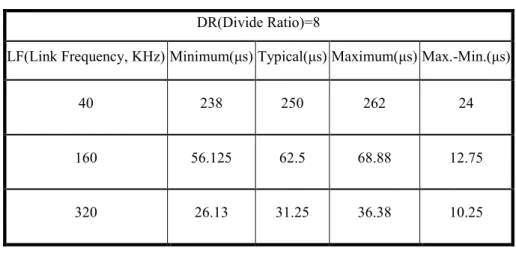
where RTcaldenotes reader-to-tag calibration symbol, and Tpridenotes link pulse- repetition interval. Some examples of the parameterT1 with divide ratio (DR) as 8 are given in Table 2. When multiple tags reply the same received R-T command in the same time slot (that is, a tag collision occurs), they may not be synchronized due to
the deviation of T1parameter in each tag. Moreover, since the variation of T1 can be nearly a tag backscatter symbol long, the orthogonality of the spread backscatter signals may be impaired if the spreading sequences require precise synchronization to maintain their mutual orthogonality. The Walsh codes, for instance, may hence be unsuitable to such a system.
Experimental measurements of three different type Gen2 tags, presented in Appendix, validate that the T1 parameter of these tags are indeed different.
Fig. 1. The tag response time [2].
Table 1. T1 link timing.
Parameter Minimum Typical Maximum
T1 MAX(RTcal,10Tpri)
(1-FT)-2μs MAX(RTcal,10Tpri)
MAX(RTcal,10
Tpri) (1- FT)+2μs
Table 2. Some examples ofT1 link timing.
DR(Divide Ratio)=8
LF(Link Frequency, KHz) Minimum(μs) Typical(μs) Maximum(μs) Max.-Min.(μs)
40 238 250 262 24
160 56.125 62.5 68.88 12.75
320 26.13 31.25 36.38 10.25
2.2 Unequal Received MBS Power
In a free space propagation model without consideration of reader antenna pattern (assuming unit gain, omni-directional), there are two main factors that can affect the strength of received MBS: one is the distance dbetween the reader and the tag, and the other is the tag antenna gain Gtag. According to the well-known Friis free space equation, the received MBS power can be written as
2 2 2
4
Back tag r
P G
P d
d L
, (2)
where PBack denotes the power of tag MBS, is the wavelength of the reader operation frequency, and L is the system loss factor not related to propagation.
Because PBack is proportional to Gtag and reverse proportional to the squares of d , we can rewrite (2) as
tag24r
P d G
d , (3)
where denotes proportional relationship.
There are a variety of tag antennas, in which the half-wavelength dipole antenna is most extensively used. The normalized antenna power gain of a half-wavelength dipole antenna is sensitive to the angle of arrival (AOA) as presented in (4).
2
2
cos cos 2
tag sin G
, (4)
where denotes the AOA of an incident wave with 0as the direction of antenna boresight. Therefore, the powers of MBS signals from any two tags can be very different because of the different AOA of impinging CW from the reader; even they are equally separated away from the reader.
Consequently, we can conclude that the received MBS power from each tag is often unequal. This phenomenon results in the inevitable near-far problem in a commonly used direct sequence spread spectrum system. Therefore, the Gold sequences, for example, may not be suitable for the system because they are not sensitive to the near-far effect.
3 Huffman Sequence Backscatter Signals
Unlike a cellular phone, a passive tag is designed as a low cost simple device, whose operation must rely on external limited power source. The tag is incapable to perform a sophisticate power control mechanism as a cellular phone does. Hence, commonly used spreading sequences with low cross-correlation, such as gold sequences used in [3], are not suitable for a passive RFID system due to the severe near-far effect.
On the other hand, the orthogonal spreading sequences like Walsh codes can resist the near-far effect. However, the orthogonal spreading sequences require synchronization to preserve their mutual orthogonality. Unfortunately, multiple tags hardly backscatter their responses simultaneously as described in section 2.1.
In order to apply CDMA technology to the passive UHF RFID system, orthogonal spreading sequences without precise synchronization are hence desired.
Huffman [5] has defined a N1chip long complex (or real) sequence, whose autocorrelation value is zero for all shift except no shift orN chip shift.
A Huffman sequence
c0 c1 cN
can be represent as
0 0 1
T
c c cN
c , (5)
and the i-th shift sequence can be written as
1 0 1
T
i ci ci cN c ci
c . (6)
Equation (6) can be obtained from (5) using
0 i i P
c c , (7)
where Pis a N+1 by N+1 permutation matrix as
1 1
0 1 0 0 0 0 1 0
0 0 0 1 1 0 0 0
N PN
. (8)
The normalized autocorrelation function of a Huffman sequence is presented as
*
1, ,
, 0,
H
ij i j
i j i j N
i j N
otherwise
c c , (9)
where *denotes the complex conjugate of , and the magnitude can be smaller than 1/
N1
.Recently, a method to generate a real Huffman sequence (also known as a shift- orthogonal sequence) has been proposed [6] and [7]. In this work, a real Huffman sequence, shown in Table 3, is used in our simulation to verify the performance of our proposed scheme.
An MBS can be generated by varying the tag reflection coefficient [8] and [9].
In order to produce a Huffman sequence spreading MBS, both magnitude and phase of the time-variant tag reflection coefficient
t in (10) need to be changed according to the Huffman sequence.
*
L A
L A
Z t Z
t Z t Z
, (10)
where ZL
t denotes the time-variant tag load impedance, ZAdenotes tag antenna impedance, and Z*A denotes complex conjugate of ZA. Note that, a normalized Huffman sequence is used because the magnitude of
t is always less or equal to 1.Rearranging (10), we have the tag load impedance ZL
t at time tas
*
1
A A
L
t Z Z Z t
t
. (11)
Therefore when the reflection coefficient
t , which is equal to the Huffman sequence at time t, is given, the corresponding tag load impedance ZL
t can be obtained.The last digit of 16-bit random number (RN16) [2] in each tag is used to determine its associated Huffman spreading sequence. In this work (N=8), if the last digit of a tag RN16 is 0, the tag uses c0 to spread its FM0 encoding backscatter signals;
otherwise, it usesc5 to spread its FM0 symbol. Note that, c0 and c5 are orthogonal.
There is only one Huffman sequence is used, the reader design is hence simpler than other CDMA system because it only use different shift of the same code to separate the received signals.
When two tags reply in the same time slot, a tag collision occurs at present passive RFID system. Depending on the power difference of the two received MBSs, a reader of present RFID system may identify one or none of the tags. However, using Huffman sequence spreading scheme, the reader can have 50% probability to simultaneously identify both tags successfully when their spreading sequences are different. If both tags have the same last RN16 digit, the reader can still indentify both tags if the link timing parameter T1 of the two tags separate more than 1 chip of the Huffman spreading sequence (providing that both MBSs are still orthogonal).
Table 3. A 9-chip normalized real Huffman sequence used in this work.
C0 C1 C2 C3 C4 C5 C6 C7 C8
0.4577 0.5763 0.1160 -0.2660 0.0633 0.2120 -0.3640 0.3440 -0.2733
4 Simulation Results
4.1 Simulation Setting
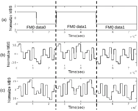
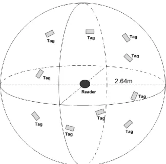
In this work, a 9-chip (M=9) Huffman spreading sequence is used as depicted in Table 3, and the corresponding waveforms of MBS are illustrated in Fig. 2. In the simulations, we assume that all tags are uniformly distributed within a sphere with radius 2.64 meter. An omni-directional reader with PEIRP 1wattis located in the center of the sphere. The antenna of each tag is assumed as a half-wavelength dipole antenna. The orientation of each tag is arbitrary, which means that AOA of the incident CW (both azimuthal angle and elevation angle) from the reader are uniformly distributed from 0 to ; Fig. 3 presents the sketch of simulation environment.
In order to simulate more realistic scenario, the tags are assumed EPCgloble Gen2 compatible [2]; link frequency (LF) of 40KHz and A Type A Reference Interval (Tari) of 25 s are assumed. The duration of a FM0 symbol in the given condition is also 25 s . The parameter T1, according to the specification [2], can vary from
238 s to 262 s with typical value as 250 s . It is noteworthy that the deviation of
T1 can be as large as 24 s , which is nearly a FM0 symbol duration. The T1of each
tag is assumed Gaussian distributed with mean of the typical value of T1, and less than 0.1% probability that the T1 falls out of the valid duration.
The simulation block diagram is presented in Fig. 4. In the simulation channel we consider free space propagation only. The power of additive white Gaussian noise (AWGN) is normalized by the power of maximum MBS signal from a tag separated 2 meter away from the reader.
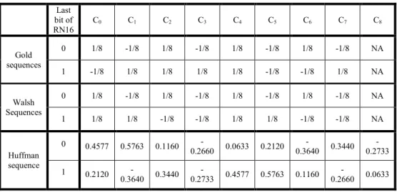
In the simulation, an 8-chip normalized Gold code spreading MBS and an 8-chip normalized Walsh code spreading MBS are compared with the proposed scheme. The normalized spreading sequences are listed in Table 4.
In order to optimize the performance of the system throughput, a modified slotted Aloha algorithm is used with the mean number of tags in a time slot as 2. The details of the cross-layer design, however, are beyond the scope of this paper.
FM0 data0 FM0 data1 FM0 data1
(a)
(b)
(c)
Fig. 2. (a) FM0 backscattering signal. (b) Huffman sequence spreading waveform using c0. (c) Huffman sequence spreading waveform using c5.
Reader
Tag Tag Tag
Tag
Tag
Tag
Tag
Tag Tag
Tag
2.64m
Reader
Tag Tag Tag
Tag
Tag
Tag
Tag
Tag Tag
Tag
2.64m
Fig. 3. The sketch of simulation environment.
Antenna Gain
+
Free-Space Loss AWGN
AcquisitionData DemodulationBPSK
DetectionFM0
Source
n X
Spreading Sequences
Tx
Rx
Channel
+
Antenna Gain
+
Free-Space Loss AWGN
AcquisitionData DemodulationBPSK
DetectionFM0 Data
Acquisition DemodulationBPSK
DetectionFM0
Source
n X
Spreading Sequences Source
n X
Spreading Sequences
Tx
Rx
Channel
+
Fig. 4. The simulation system.
Table 4. The spreading sequences used in the simulation.
Last bit of
RN16 C0 C1 C2 C3 C4 C5 C6 C7 C8
Gold sequences
0 1/8 -1/8 1/8 -1/8 1/8 -1/8 1/8 -1/8 NA
1 -1/8 1/8 1/8 1/8 1/8 -1/8 -1/8 1/8 NA
Walsh Sequences
0 1/8 -1/8 1/8 -1/8 1/8 -1/8 1/8 -1/8 NA
1 1/8 1/8 -1/8 -1/8 1/8 1/8 -1/8 -1/8 NA
Huffman sequence
0 0.4577 0.5763 0.1160 -
0.2660 0.0633 0.2120 -
0.3640 0.3440 - 0.2733
1 0.2120 -
0.3640 0.3440 -
0.2733 0.4577 0.5763 0.1160 -
0.2660 0.0633
4.2 Simulation results
The throughput of the system is defined as
number of total tags Throughput
number of used slots in an inventory process
. (12)
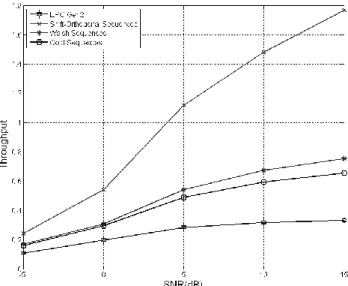
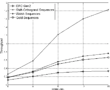
The performance comparisons for different numbers of tags are listed in Fig. 5 to Fig. 7. Apparently, the proposed scheme outperforms other multiple access methods, especially in high SNR conditions. Walsh code spreading method is the second best choice. All results demonstrates that using TDMA technology only, such as EPC Gen2 slotted Aloha algorithm, results in poor performance in an inventory process.
Fig. 5. An inventory of 500 tags. Note that the Shift-Orthogonal sequence denotes the proposed scheme.
Fig. 6. An inventory of 1000 tags. Note that the Shift-Orthogonal sequence denotes the proposed scheme.
Fig. 7. An inventory of 2000 tags. Note that the Shift-Orthogonal sequence denotes the proposed scheme.
5 Conclusions
A novel passive tag backscatter scheme using Huffman spreading sequences is proposed, which can effectively improve an inventory process. The performance of several studied multiple access schemes are compared. Simulation results validate the performance enhancement of our proposed system. However the system may require a reader with high sensitivity, so that the levels of backscatter signals can be detected correctly. In addition, to implement such a system, further studies of cross-layer technologies combining TDMA (Mac layer) and CDMA (Physical layer) technologies are necessary.
Acknowledgments.
This study is partially supported by the National Science Council of Taiwan under grant no. NSC 96-2221-E-011-017.
References
1."18000-6 Part 6 – Parameters for Air Interface Communications at 860 to 960 MHz,"
International Organization for Standardization (2004)
2. EPCTM Radio-Frequency Identity Protocols Class-1 Generation-2 UHF RFID Protocol for Communication at 860MHz-960MHz Version 1.09, http://www.epcglobalinc.com
3. Rohatgi, Anil,: Implementation and Applications of an Anti-Collision Differential-Offset Spread Spectrum RFID System, Master Thesis of Science in the Electrical and Computer Engineering of Georgia Institute of Technology School (2006)
4. Pillai, V., et al.: A technique for simultaneous multiple tag identification. Fourth IEEE Workshop on Automatic Identification Advanced Technologies, pp.35-38 (2005)
5. Huffman, D. A.: The generation of impluse-equivalent pulse train. IEEE Trans. Inf. Theory, vol. IT-8, pp.S10-S16 (1962)
6. Tanada, Y.: Synthesis of a set of real-valued shift-orthogonal finite-length PN sequences.
IEEE 4th International Symposium on Spread Spectrum Technique and Applications, pp.58- 62 (1996)
7. Tanada, Y. Orthogonal Set of Huffman Sequences and Its Application to Suppressed- Interference Quasi-Synchronous CDMA System. IEICE Trans. Fundamentals, vol. E89-A, No. 9 (2006)
8. Yen, C., Gutierrez, A. E., Veeramani, D., and van der Weide, D.: Radar cross-section analysis of backscattering RFID tags. IEEE Antennas and Wireless Propagation Letters, vol.6, pp. 279-281 (2007)
9. Finkenzeller, K.: RFID Handbook, 2nd edition, Wiley (2003)
Appendix
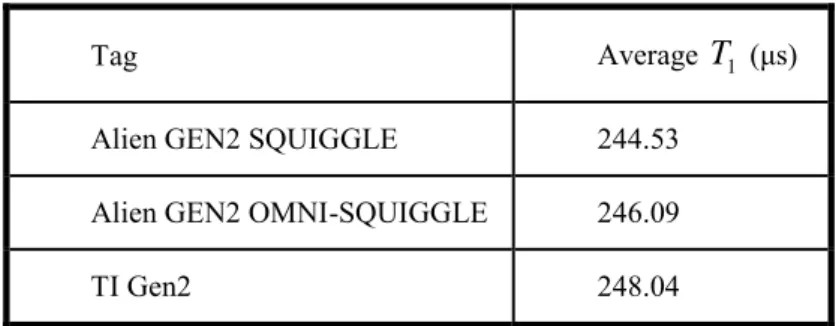
Some experimental results of T1link timing parameter of different tags are presented in this section. Table A presents the statistical results and Fig. A illustrates how the measurement is performed.
Table A. Experimental T1measurements using three different type Gen2 tags.
Tag Average T1 (μs)
Alien GEN2 SQUIGGLE 244.53
Alien GEN2 OMNI-SQUIGGLE 246.09
TI Gen2 248.04
Fig. A. A snapshot of T1measurement of a TI Gen2 tag.

![Fig. 1. The tag response time [2].](https://thumb-ap.123doks.com/thumbv2/9libinfo/9122615.407257/18.892.203.720.451.622/fig-the-tag-response-time.webp)