行政院國家科學委員會專題研究計畫 成果報告
一個基於全方位與 PTZ 雙攝影機協調控制的人體追蹤與人 臉辨識之高畫質機器人視覺系統
研究成果報告(精簡版)
計 畫 類 別 : 個別型
計 畫 編 號 : NSC 98-2221-E-011-119-
執 行 期 間 : 98 年 08 月 01 日至 99 年 07 月 31 日 執 行 單 位 : 國立臺灣科技大學資訊工程系
計 畫 主 持 人 : 范欽雄
處 理 方 式 : 本計畫涉及專利或其他智慧財產權,2 年後可公開查詢
中 華 民 國 99 年 08 月 05 日
一個基於全方位與 PTZ 雙攝影機協調控制的人體追蹤與人臉辨識之 高畫質機器人視覺系統
A High-Definition Robot Vision System for Human Body Tracking and
Face Recognition Based on the Cooperative Control of Omnidirectional and PTZ Cameras
計畫編號:NSC-98-2221-E-011-119
執行期限:民國 98 年 8 月 1 日至 99 年 7 月 31 日
主持人:范欽雄 國立台灣科技大學資訊工程系 副教授
計畫參與人員:羅金松 國立台灣科技大學資訊工程系 碩士班研究生
中文 中文中文 中文摘要摘要摘要摘要
全方位攝影機因為能提供 360 度的場景資訊而被廣 泛的應用在影像監控及機器人視覺上,但是全方位攝影機 有一個明顯的缺點:僅能低解析度的影像,使得離此攝影 機較遠的物體無法被正確的辨識。為了克服這個問題,我 們提出一個結合全方位攝影機和 PTZ 攝影機的協力視覺追 蹤系統,它係藉由全方位攝影機收到的全景影像裡偵測及 追蹤人臉,並控制 PTZ 攝影機去注視所選擇的人臉,以獲 得高解析度的人臉影像。首先,人臉偵測的程序係利用時 間差異法及膚色篩選器取得移動的人臉;然後,被偵測到 的人臉會傳送給利用粒子濾除器,以達到即時性人臉追蹤 需求的人臉追蹤程序,當目標人臉被選擇了後,PTZ 攝影 機會快速地被引導去注視目標並放大之。接著,人臉追蹤 的程序改由 PTZ 攝影機接收到的影像繼續進行人臉追蹤直 到目標人臉離開監視範圍;再將人臉追蹤程序切換回使用 全方位影像重新開始追蹤,而達到雙攝影機協力追蹤人臉 的閉迴路系統。於實驗結果顯示,我們所提方法的人臉追 蹤正確率在一般的情況下高於 95%,而在啟動 PTZ 攝影 機追蹤的情況下高於 82%。整體的系統效能在未啟動 PTZ 攝影機追蹤的條件下達到每秒 20 個畫面的速度,而在啟 動 PTZ 攝影機追蹤後仍然可達到每秒 5 個畫面的速度;根 據本計畫所發展的系統在人機介面及影像監控方面相當有 助益。
關鍵詞關鍵詞關鍵詞
關鍵詞:::高畫質人臉追蹤、時間差異、膚色與髮色濾波、: 粒子濾除器、全方位與 PTZ 攝影機之融合。
A
BSTRACTThe omni-directional cameras providing 360 degrees field of view (FOV) are widely used in video surveillance and robot vision applications. However, the omni-directional cameras have an obvious drawback; that is, only low-resolution images captured. Therefore, the objects are not able to be correctly identified if they are far from the omni-directional cameras. To overcome this problem, we propose a high-definition human face tracking system using the fusion of omni-directional and pan-tilt-zoom (PTZ) cameras. Our system first detects and tracks human faces in the panoramic images received from an omni-directional camera, and then controls the PTZ camera to fixate at a target face for capturing a high-resolution image. At
the beginning, the human face detection procedure obtains moving human faces by means of temporal differencing together with skin and hair color filtering. The detected human faces are subsequently fed to the face tracking procedure which employs a particle filter for iteratively tracking human faces. Once a target human face is selected, the PTZ camera is directed to stare at the target and zoom in it speedily. Then the face tracking procedure turns to use the images received from the PTZ camera for continuously tracking the target face until it is outside the FOV of the camera.
Keywords: High-definition human face tracking, temporal differencing, skin and hair color filtering, particle filter, fusion of omni-directional and PTZ cameras.
1. I
NTRODUCTIONSince the FOV of a traditional dioptric camera is confined to cover part of a natural scene, the object of interest will only be detected while it is visible. In contrast to the limited FOV of traditional cameras, omni-directional cameras capture 360 degrees scene information and output them in a single image.
Owing to the advantage of wide FOV, omni-directional cameras are broadly used in vision-based applications, such as robotic security guard [1].
A novel approach which combines omni-directional and PTZ cameras as a dual camera system is available in public area monitoring and target tracking recently. Meanwhile, this approach overcomes both the shortages of low-resolution images captured with an omni-directional camera and limited FOV images captured with a PTZ camera. Yao et al.
concentrated on the performance improvement of a cooperative
camera system (omni-directional and slaved PTZ cameras) and
developed a distributed Kalman filter to exchange estimated
trajectories among cameras [2]. Human faces are the most
intuitive biometric features for human identification. A
conventional robot vision system usually consists of off-the-
shelf cameras that have limited view angles and could
detect/track human faces just in a short distance accurately. The
omni-directional cameras, possessing 360 degrees FOV, can
overcome the shortage of the limited view angle. The robot
vision system with the omni-directional camera will be
extensively utilized in video surveillance and intelligent
appliances, because of the advantage of detecting activities in
full directions. However, this robot vision system is still
shortsighted and cannot obtain a clear human face for further identification. Our main research is to set up a human face tracking system which increases the effective view distance and provides a high-definition human face by aid of fusing the omni-directional and PTZ cameras.
2. S
YSTEMD
ESIGHNO
VERVIEWFor enhancing the overall robustness and the spatial coverage of a robot vision system, we implement a dual camera system which tracks targets on the ground plane for an autonomous mobile robot. Both the omni-directional and PTZ cameras are mounted on the robot platform and the on-board PC performs face tracking on the images which are received from the omni-directional camera, then direct the PTZ camera to gaze at a selected target and rapidly zoom in it. The enlarged target is continuously tracked by the PTZ camera until it exceeds the FOV of the camera.
Besides the dual camera system, the power system of the robot platform supplies two DC motors to drive two main wheels, whereas two casters are added for the platform balance in the course of movement. Moreover, six ultrasonic sensors, a digital compass module, and an acceleration sensor, are placed at the bottom level of the platform. In the middle level, an on- board PC which contains an Intel Dual Core 2 1.66 GHz processor and one Giga byte system memory is assembled.
The video frames output of the omni-directional and PTZ cameras are captured by two USB 2.0 video grabber devices and sent to the PC through an USB interface, respectively. Fig.
1 shows our experimental robot platform.
Figure 1. The experimental mobile robot platform.
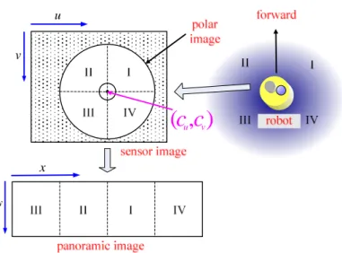
The human face tracking system that we propose first gets a polar image from an omni-directional camera and converts it to a panoramic one. The motion analysis is then applied to the panoramic image for acquiring motion blobs. Following that, the human face detection algorithm is activated for verifying
the blobs to obtain moving faces. When a human face is detected, it is continuously located and its position is also estimated. Subsequently, the system can conduct the PTZ camera to gaze at the target of interest; that is, a selected human face, and appropriately zoom in it. If the target moves outside the FOV of the PTZ camera, the system makes a fresh start to detect human faces using the omni-directional camera. It is called a close-loop face tracking mechanism. The system block diagram is depicted in Fig. 2. Additionally, Fig. 3(a) demonstrates the original polar image obtained from the omni- directional camera, which is converted to a panoramic image as Fig. 3(b) shows.
Figure 2. The block diagram of our human face tracking system.
3. C
AMERAC
ALIBRATIONCamera calibration builds up the geometry correspondence
between the omni-directional and PTZ cameras and estimates
the intrinsic and extrinsic parameters for mapping the 3D real
world into an image plane. In this section, we first describe the
calibration method for our experimental omni-directional
camera. Next, we elaborate the PTZ camera calibration
procedure used for controlling the PTZ camera to stare at the
target that was detected and tracked through the omni-
directional camera beforehand.
(a)
(b)
Figure 3. Omni-directional image acquisition: (a) the polar image obtained from the omni-directional camera; (b) the panoramic image resulting from converting the polar image.
A. Omni-directional Camera Calibration
Omni-directional camera calibration is a lively research area and various projection models are proposed for actual imaging processes [3]. The calibration for such an omni- directional camera mainly includes the estimation of an effective image region, image center, and transformation function.
1) Effective image region
The number of effective pixels received from a camera, locating in the polar image, is quite less than the total number
of image pixels. Retrieving the effective image region can reduce the processing of unused pixels; this also increases the
efficiency of subsequent image processing. The estimation process starts by placing a white tissue on the cataoptric mirror that is mounted over the CCD camera. Consequently, a whole white polar image is obtained from the omni-directional camera sensor. Then the image is converted to a gray level one and binarized by means of an adequate threshold. The external radius R
extand internal radius R
intof the polar image are acquired by estimating the radii of a donut-shaped object. The image center can also be received from computing the center of the object.
2) Image transformation
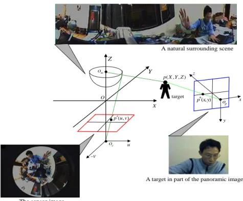
The image taken by the omni-directional camera is originally in polar form, and must be transformed to a panoramic one for the convenience of tracking targets later. Fig.
4 shows the geometry mapping between the omni-directional and PTZ cameras. In the literature, several algorithms have been proposed for omni-directional image transformation [4].
To accomplish this, our method first acquires the relationship between the polar and p
anoramic images using (1), which is graphically represented in Fig. 5.
( ) sin( and ( ) cos( ,
=cu+ ) =cv+ )
u S y x v S y x
(1) where c
uand c
vare the coordinates of the common center of the polar and panoramic images; u and v are the pixel coordinates in the polar image domain; x and y are the pixel coordinates in the panoramic image domain, and S(
˙)is the stretching function along the y-axis.
O
X Z
Y
Om
x
y z
op
Oc
( , , ) p X Y Z
u
−v
target * ( , ) p x y A natural surrounding scene
A target in part of the panoramic image ( , )
′ p u v
The sensor image
Figure 4. The geometry mapping between the omni-directional and PTZ cameras.
x
y
v
( , ) c c
u vu
Figure 5. The relationship between the polar and panoramic images.
Because our color-based face detection and tracking scheme is still efficacious for running on skewed and distorted images, we apply one-to-one mapping along the vertical axis for alleviating the computational load. The following expresses such a stretching function.
S y ( )
=Hp−y (2) , where H
pis the same as R
extdenoting the height of the panoramic image.
B. PTZ Camera Calibration
The goal of PTZ camera calibration is to figure out the relationship between the omni-directional and PTZ cameras for directing the PTZ camera to focus on the selected target. For this intention, the pose of the PTZ camera for target fixation is maintained by continuously estimating its required panning and tilting angles. However, traditional camera calibration is unable to meet this specific requirement.
Due to the characteristic of an omni-directional camera (360 degrees FOV), the situating direction of a target of interest can be obtained from calculating the azimuth where it appears. Given the x-coordinate of a target position in the panoramic image, denote θ
1and θ
2as the previous and desired panning angles, respectively. And W
pis the width of the panoramic image. Fig. 6 illustrates an example of the panning control that turns the lens of the PTZ camera from θ
1to θ
2horizontally. The algorithm for determining the panning angle θ
pand the panning direction D
pof a PTZ camera are stated as follows.
θ1 θ2
0o 360o
p x W
Figure 6. Illustration of the panning control from θ1 to θ2.
The mirror equipped in our omni-directional camera is hyperbolic and it provides the view by 15 degrees above the horizon and 60 degrees below. So, the relationship between a target point p*(x,y) in the panoramic image and the angle φ referred to the vertical axis through the standing position of the omni-directional camera should be linear under the assumption that the target is located on the ground plane and its size is known. We evaluate the function f(y) associated with the mapping geometry between the y-coordinate of p*(x,y) and the angle φ related to the hyperbolic mirror by selecting several points on a calibration board which is taken in an image by the
Input: a target position with the x-coordinate, the previous panning angle θ
1, and the width W
pof a panoramic image.
2 360 / ;
θ = ⋅x ° Wp
If
abs(θ2−θ1)>180°then If
θ2>θ1then
θp =360° −θ2+θ1; Dp =“left;”
Else
θp=360° − +θ θ1 2; Dp =“right;”
End If
Else
θp=abs(θ θ2- 1);
If
θ2>θ1then
Dp =“right;”Else
Dp =“left;”
End If End If
Output: the panning angle θ
pand the panning
direction D
p.
omni-directional camera and then transformed into a panoramic image.
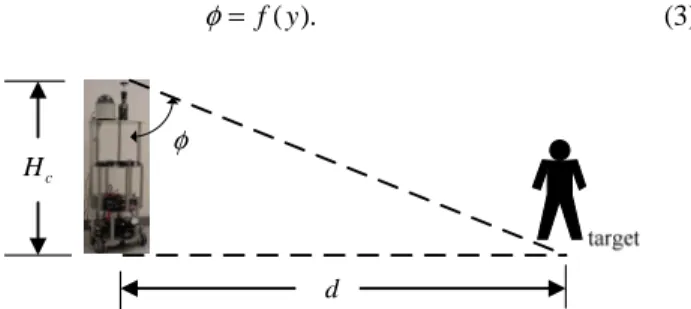
Fig. 7 graphically shows an example for angular calibration and (3) depicts the aforementioned mapping function.
φ = f y (3) ( ).
Hc
d
φ
Figure 7. The relationship between the angle
φ
and the distance d.Owing to the characteristic of the hyperbolic mirror, the relationship between the distance of a target away from the two cameras and the angular value of the target in the polar image is linear. Once the angle φ is obtained, the distance d of the target may be calculated by the following equation.
tan( ), φ
=
cd H (4) where H
cis the altitude to which the omni-directional camera is set.
Substituting (3) into (4), the distance d of the target may be estimated by the y-coordinate using
tan( ( )).
=
cd H f y (5) At last, given a known altitude H
twhere the PTZ camera is set, the value of the tilting angle θ
tfor the PTZ camera fixating at the target is derived from
arctan( ).
θ
t= H d (6)
t4. F
ACED
ETECTIONA
NDT
RACKINGHuman face is one of the main biometric features for security applications, and face detection is the first and important processing step for an automated face or facial expressions recognition system. The following first elaborates our face detection procedure. Next, the face tracking algorithm that we develop is presented.
C. Face Detection
Face detection is a procedure to locate human faces in a scene. Several approaches in the field of face detection, fast and accurate, have been proposed in the recent decade [5]. Our face detection procedure mainly comprises temporal differencing, motion analysis, and skin and hair color filtering. Due to the limitation to the length of writing, the motion analysis is not expressed herein.
1) Temporal differencing
Temporal differencing that acquires the dissimilarity between two consecutive images is a speedy method to retrieve motion blocks with a stationary camera. However, the detected motion blocks might be moving objects, noise, shadows of moving objects or the variance generated from lighting change.
The blocks in which belong to moving objects are only interested. The temporal difference of images at time step t is estimated by the following equation that constitutes a binary image using a threshold ε .
1 if
10 otherwise,
ε
∧
−
−≥
=
t t
t
I I
I (7)
where I
tand I
t-1are the gray level images at time steps t and t-1, respectively.
2) Skin and hair color filtering
Color filtering which detects specific colors is a most intuitive and fast method to find a human face. It is utilized to screen out the pixels that do not possess skin or hair colors after retrieving motion blocks. In addition to skin color filtering [6], hair color filtering is applied to prevent incomplete face regions from detection lost. The method, based on the YC
bC
rcolor model proposed in [7], is adopted for hair color regions detection. By combining the above two color filtering outcomes, we obtain human face regions in a high confidence, each of which can be represented by a binary image. That is, the moving human faces are located initially.
D. Face Tracking
The aim of face tracking is to keep on locating human faces detected previously in real time. Namely, the trajectory of a moving face is received from successive image frames without interruption. This accomplishment involves three main phases:
candidate region location, feature extraction, and target tracking. The fundamental technique that we utilize is a particle filter [6], which is composed of four parts: propagation, observation, selection, and estimate depicted in brief below.
5. E
XPERIMENTALR
ESULTSGiven: a sample set S
t−1= { ( s
t( )−i1, π
t( )−i1) i = 1, 2,..., N } at
time step t-1, perform the following steps:
1. Propagation: produce each sample s
t( )i−1with the weight
( ) 1 i
π
t−by a dynamic model to obtain the sample set S
t. 2. Observation: weigh the samples using both color and motion cues as:
1) Calculate the distance between each sample and the target by
Dis
t( )i= 1 − M
t( )i, where M
t( )iis a linear combination of color and motion cues.
2) Weigh each sample with
( ) 2 ( )
2
1 exp( )
2 2
i
i t
t
π Dis
πσ σ
= − , where σ is the
standard deviation of a Gaussian distribution.
3. Selection: if π
t( )iexceeds or equals a threshold, select C
ieven-weighted samples.
4. Estimate: acquire the state of the sample s
t⊗with the largest weight as:
*( )j
for arg max
*( )it t t
i
π
⊗= π j = π
The visual tracking system that we create is a mobile robot platform equipped with an omni-directional camera and a PTZ camera mounted on the top. The distance H
tfrom the ground plane to the omni-directional camera is 89 cm and H
crepresenting the altitude of the PTZ camera is 83 cm. The resolution of the image frames received from both the omni- directional and PTZ cameras is 640 × 480 pixels, whereas the panoramic image size is set to 360 × 240 pixels. We conduct many experiments in our laboratory and the corridor of the Research Building at National Taiwan University of Science and Technology. The results of distance estimation as well as face detection and tracking are presented in this section orderly.
E. The Results of Face Detection
The moving faces are found by applying the face detection procedure to the panoramic images. This procedure consists of temporal differencing, motion analysis, skin and hair color filtering, and connected component labeling. The entire process takes 45 ms regardless of the number of moving faces in a scene, and an example of detecting a single face bounded with a box is shown in Fig. 8.
Figure 8. Illustration of a single face detected.
The detection rate is evaluated by performing face detection tests on different backgrounds and lighting conditions. TABLE I lists the results of the face detection tests in the cases of locating multiple faces.
TABLE I. THE EVALUATIONOF MULTIPLE FACES DETECTION Experimental
condition
Number of faces
Number of detected faces
Detection rate
Error rate
Normal 104 95 91.3% 8.7%
Skin color-like objects in the background
112 92 82.1% 17.9%
Low lighting 107 80 74.8% 25.2%
F. The Results of Face Tracking
Since there are no certain ways to validate the face tracking by the fusion of the omni-directional and PTZ cameras, we categorize the validation into two kinds: one is the accuracy rate of face tracking with only enabling the zoom in/out control of the PTZ camera which successfully gazes at the target, and another is that with enabling the pan/tilt/zoom control of the PTZ camera. The accuracy rate of face tracking of each kind is measured by the ratio of the number of the faces effectively tracked to that appearing in natural scenes. Fig. 9 demonstrates an example of tracking multiple faces without enabling the pan and tilt control of the PTZ camera. The evaluation of multiple faces tracking under this condition is recorded in TABLE II.
On the whole, the tracking accuracy in a corridor is higher than
that in our laboratory because the latter is possessed of a cluttered background. The simple background in the corridor has less noise disturbance, so that the accuracy rate of face tracking increases. The entire face tracking process takes about 50 ms. It is obviously seen that the performance of a single face tracking is preferable to that of multiple faces tracking in each of experimental sites.
(a)
(b)
Figure 9. Illustration of multiple faces tracking with enabling the zoom in/out control: (a) the tracked face at frame #10; (b) the tracked face at frame #40.
TABLE II. THE EVALUATIONOF MULTIPLE FACES TRACKINGWITH ENABLING THE ZOOM IN/OUT CONTROL
Experimental site
Number of faces
Number of tracked faces
Accuracy rate
Error rate Our
laboratory 146 119 81.5% 18.5%
A corridor 139 115 82.7% 17.3%
6. C
ONCLUSIONSThe robot vision system that we have presented can detect and track human faces in omni-directional images;
furthermore, it can control the PTZ camera to stare at the
selected human face at a high accuracy rate. Our system not
only has the advantage of a wide FOV brought by the omni-
directional camera, but also employs the PTZ camera to
overcome the low resolution problem. Meanwhile, with the
advantage of the wide FOV, the moving human faces in the
area surrounding the mobile robot will be located and tracked
efficiently. Our experimental results manifest that the face
detection and tracking in panoramic images using the omni-
directional camera only costs 50 ms (i.e., 20 fps), whereas it
costs 200 ms in zoom-in images using the PTZ camera with
enabling the pan/tilt/zoom control. The performance of this
robot vision system is very encouraged and quite useful in
human interaction and video surveillance tasks.
R
EFERENCES[1]
P. Biber, S. Fleck, and T. Duckett, “3D modeling of indoor environments for a robotic security guard,” in Proceedings of the IEEE Computer Society Conference on Computer Vision and Pattern Recognition, 2005, San Diego, California, vol. 3, pp. 124-130.
[2]
Y. Yao, B. Abidi, and M. Abidi, “Fusion of omni- directional and PTZ cameras for accurate cooperative tracking,” in Proceedings of the IEEE International Conference on Video and Signal Based Surveillance, 2006, Sydney, Australia, p. 46.
[3]
J. Kannala and S. Brandt, “A generic camera calibration method for fish-eye lenses,” in Proceedings of the International Conference on Pattern Recognition, 2004, Cambridge, United Kindom, pp. 10-13.
[4]
G. Scotti, L. Marcenaro, C. Coelho, F. Selvaggi, and C. S.
Regazzoni, “Dual camera intelligent sensor for high definition 360 degrees surveillance,” IEE Proceedings- Vision Image and Signal Processing, vol. 152, no. 2, pp.
250-257, 2004.
[5]
K. C. Yow and R. Cipolla, “Feature-based human face detection,” Image and Vision Computing, vol. 15, no. 9, pp. 712-735, 1997.
[6]
C. S. Fahn, M. J. Kuo, and K. Y. Wang, “Real-time face tracking and recognition based on particle filtering and AdaBoosting techniques,” in Proceedings of the 13th International Conference on Human-Computer Interaction, 2009, San Diego, California, pp.198-207.
[7]
K. T. Song and W. J. Chen, “Face recognition and
tracking for human-robot interaction,” in Proceedings of
the International Conference on Systems, Man, and
Cybernectics, 2004, Hauge, Netherlands, pp. 2877-2882.
國科會補助計畫衍生研發成果推廣資料表
日期 2010年08月05日
國科會補助計畫
研發成果名稱
發明人 (創作人)
技術說明
技術移轉可行性及 預期效益 技術/產品應用範圍
產業別
計畫名稱:
計畫主持人:
計畫編號: 學門領域:
(中文)
(英文)
成果歸屬機構
(中文)
(英文)
一個基於全方位與PTZ雙攝影機協調控制的人體追蹤與人臉辨識之高畫質 機器人視覺系統
范欽雄
98 -2221-E -011 -119 - 圖形辨識 基於隱藏式馬可夫模型學習機制的人體動作辨識技術
Human Actions Recognition Techniques Based on the Learning Mechanism of HMMs
國立臺灣科技大學 范欽雄,吳文華
近年來,人類動作辨識技術已在電腦視覺領域中備受關注,在自動監視系統、
人機界面、居家安全照護系統和智慧型居家環境等方面的應用中皆佔有主要的 地位。有鑑於此,我們提出一個基於隱藏式馬可夫模型的人類動作辨識方法,
本方法主要包含移動物體捕捉、特徵擷取、動作分段以及動作辨識四個步驟。
首先,前景人物透過背景剪裁方法由背景模型中抽取出來,並將抽取出來影像 轉換成二值化的影像格式;接著,採取星型骨架描述人類動作姿勢特徵,星型 骨架為前景人物輪廓突出點與人物中心點連結而成,此外,也將時間影像序列 轉為特徵序列,並進一步產生符號序列,藉以為動作建構隱藏式馬可夫模型。
在動作分段步驟中,觀察前景人物輪廓突出點,計算出固定不動的突出點個數 變化,藉此區分出不同動作的符號序列,同時結合滑動窗口技巧,將不同動作 一一分段出來,並於事先的訓練階段中,為所有動作建立隱藏式馬可夫模型,
並在最後的動作辨識步驟中,找出與分段動作符號序列最匹配的動作模型,此 動作即為辨識的結果。此外,我們也利用了星型骨架中心點的移動速度差異,
來辨識人類跌倒的動作。
In this research, we proposed human actions recognition techniques based on HMMs. The star skeleton was used to effectively and efficiently represent the features of postures for each human action.To handle the recognition in continuous actions, the action segmentation is conducted by combining the sliding window scheme with stable contact detection. The extreme points of star skeleton
remaining in the same place for a long enough period are the stable contacts. Primitive motion units (PMUs) that have a consistent number of stable contacts are regarded as a segmented action. When the period of PMU is too long, we employ sliding window to segment the continuous actions. We build an HMM for each action type except
“fall-down”, and the recognition result is determined as the category which the best matched the observed sequence. Moreover, we 資訊服務業
自動監視系統、人機界面、居家安全照護系統和智慧型居家環境
本技術可應用在任何視覺追蹤及辨識系統上,預估在有應用視覺型影像追蹤辨識系統 的市場上都有相當高的優勢。
註:本項研發成果若尚未申請專利,請勿揭露可申請專利之主要內容。
國科會補助專題研究計畫成果報告自評表
請就研究內容與原計畫相符程度、達成預期目標情況、研究成果之學術或應用價 值(簡要敘述成果所代表之意義、價值、影響或進一步發展之可能性)、是否適 合在學術期刊發表或申請專利、主要發現或其他有關價值等,作一綜合評估。
1. 請就研究內容與原計畫相符程度、達成預期目標情況作一綜合評估
■達成目標
□未達成目標(請說明,以 100 字為限)
□實驗失敗
□因故實驗中斷
□其他原因 說明:
2. 研究成果在學術期刊發表或申請專利等情形:
論文:□已發表 ■未發表之文稿 □撰寫中 □無 專利:□已獲得 ■申請中 □無
技轉:□已技轉 □洽談中 ■無 其他:(以 100 字為限)
3. 請依學術成就、技術創新、社會影響等方面,評估研究成果之學術或應用價 值(簡要敘述成果所代表之意義、價值、影響或進一步發展之可能性)(以 500 字為限)
全方位攝影機可以提供 360 度的場景資訊,但是它有一個明顯的缺點:僅能低解析度的影 像,使得離此攝影機較遠的物體無法被正確的辨識。為了克服這個問題,我們提出一個結 合全方位攝影機和 PTZ 攝影機的協力視覺追蹤系統,它係藉由全方位攝影機收到的全景影 像裡偵測及追蹤人臉,並控制 PTZ 攝影機去注視所選擇的人臉,以獲得高解析度的影像。
首先,人臉偵測的程序係利用時間差異法及膚色篩選器取得移動的人臉;然後,被偵測到 的人臉會傳送給利用粒子濾除器建構的即時性人臉追蹤系統進行追蹤,當目標人臉被選擇 後,PTZ 攝影機會快速地去注視目標並放大之。接著,人臉追蹤的程序改由 PTZ 攝影機接 收到的影像繼續進行追蹤直到目標人臉離開監視範圍;再將追蹤程序切換回使用全方位影 像重新開始追蹤,而達到雙攝影機協力追蹤人臉的閉迴路系統。於實驗結果顯示,人臉追 蹤正確率在一般的情況下高於 95%,而在啟動 PTZ 攝影機追蹤的情況下高於 82%。整體的 系統效能在未啟動 PTZ 攝影機追蹤的條件下達到每秒 20 個畫面的速度,而在啟動 PTZ 攝 影機追蹤後仍然可達到每秒 5 個畫面的速度;根據本計畫所發展的系統在人機介面及影像 監控方面相當有助益。