Research Express@NCKU - Articles Digest
Research Express@NCKU Volume 20 Issue 8 - November 25, 2011 [ http://research.ncku.edu.tw/re/articles/e/20111125/1.html ]
An Optimal Fin Design Problem in Estimating the
Shapes of Longitudinal and Spine Fully Wet Fins
Cheng-Hung Huang
*and Yun-Lung Chung
Department of System and Naval Mechatronic Engineering, College of Engineering, National Cheng Kung University
CMES-Computer Modeling in Engineering & Sciences, Vol. 44, 249-279, 2009.
H
eat exchangers have been in use over a long period of time and are widely seen inmany engineering applications such as air-conditioning and ventilation refrigeration, cooling systems and chemical engineering in industrial. For this reason it is quite nature that many works have been done in order to improve the design of the fins.
The objective of this work is to estimate the optimum shapes for the longitudinal and spine fully wet fins by using the technique of inverse design problem based on the desired fin volume and fin efficiency. For the fully wet fin surfaces, the surface temperature of
the fin is generally below the dew point of the surrounding air and therefore moisture is condensed on the fin surface to evolve latent heat. For this reason mass transfer occurs simultaneously with the heat transfer.
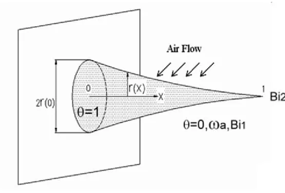
Figures 1 and 2 illustrate the dimensionless geometry for the spine and longitudinal fully wet fins considered here. To test the accuracy of the present numerical solution we have solved for the temperature distributions for
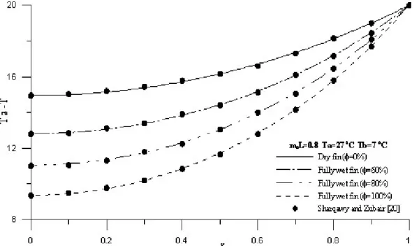
longitudinal and spine fins, respectively, and then compared with the results obtained from analytical expressions. Figures 3 and 4 show the results, respectively. From these results it is concluded that the numerical solution for the direct problem is very accurate in the present study.
A comparison of optimum fin shape with the fin shapes with efficiency ф = 0.2 and 0.25 and three common
longitudinal fins is shown in Figure 5 for V = 0.015, Bi1 = 0.075, Bi2 = 0.0 and Φ = 80 %. It can be learned that as the desired fin efficiency is less than the optimum efficiency, fin base thickness r(0) becomes thinner but the rest of fin thickness r(x) becomes thicker. Moreover the outer edge of the fin surface will become thicker than the
optimum one.
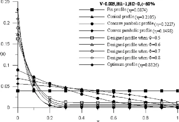
Finally a comparison of optimum fin shape with the fin shapes of designed efficiency ф = 0.5, 0.6, 0.7 and 0.8 and
four commonly seen spine fins is shown in Figure 6 for V = 0.005, Bi1 = 1.0 and Bi2 = 0.0 at Φ = 1 60%. From Figure 6 it is learned that as the desired fin efficiency is less than the optimum efficiency, fin base thickness r(0) becomes thinner but the rest of fin thickness r(x) becomes thicker and the outer edge of the fin surface will become thicker than the optimum one to satisfy the desired fin volume.
Research Express@NCKU - Articles Digest
Research Express@NCKU - Articles Digest
Figure 3. The comparison of present numerical solutions with exact solutions for rectangular longitudinal fin profile
Research Express@NCKU - Articles Digest
Research Express@NCKU - Articles Digest
Figure 6. The comparison of optimum and designed fin shapes with many other fin shapes at V = 0.005 with Bi1 = 1.0 and Φ = 60%