Chapter 4
A Fully Distributed Fault-Tolerant Location Management Scheme
_____________________________________
4.1 The System Model
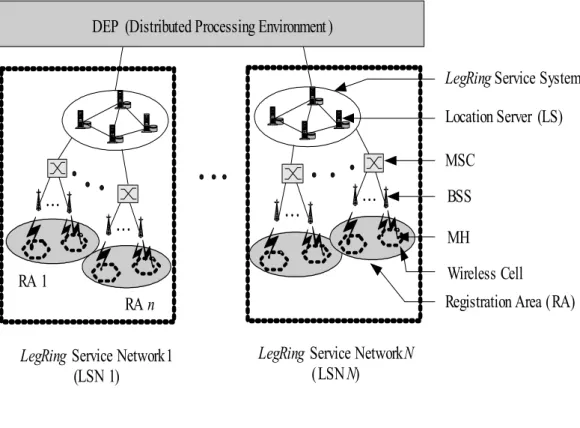
As illustrated in Fig. 4-1, our network topology can be separated into two parts:
LegRing service network (LSN) and distributed processing environment (DPE) [39].
A distributed processing environment is a middleware kernel for telecommunication systems based on distributed and object-oriented computing that enables easy implementation of a distributed database for location management.
Different LSNs are connected via a DPE. Each LSN has a LegRing service system, which includes servers that act as location servers (LSs). These LSs perform the update/query procedures and are used to store location and service information for each registered user of the wireless network.
In our model, the system is modeled as a geographical area that consists of a lot
of cells. The cells are aggregated into contiguous geographical regions called registration areas (RAs). The mobile node, referred to as mobile host (MH), is a part of one and the only one cell at a time. A fixed base station, called mobile support station (MSS), supports each cell. The communication between MH and MSS is through radio waves or infrared waves which are wireless. The mobile support station is static and connected through dedicated wire-line link to a mobile switch center (MSC). An MSC, which typically provides switching and can be viewed as a bridge for connecting the wireless network and the wired network, may manage several RAs. To simplify the discussion in this paper, we shall assume there is only one LA within an MSC. Each mobile host can communicate with any particular node
BSS MSC
Registration Area (RA) MH
LegRing Service Network 1 (LSN 1)
Wireless Cell Location Server (LS) DEP (Distributed Processing Environment )
LegRing Service System
RA 1
RA n
LegRing Service Network N (LSN N)
Fig. 4-1. Logical view of network topology.
by querying the location information from location server(s) in the LegRing service system.
The coverage areas of RAs were initially decided by the system. The LegRing algorithm was run before the system processing the update and query procedures.
Therefore, the quorum tables were built initially (but may be rebuilt if the system needs to change the coverage of some RAs in few times).
4.2 Design Approach for Location Update
In a traditional location management scheme, an update procedure that would need to coordinate between HLR and VLRs will occur whenever an MH moves to a new RA. In our approach, when an MH moves to a new RA in the same LSN, instead of updating information to the HLR, it merely reports its location to the LSs of selected quorum in the local LSN. We divide the update procedure into two types:
local update and remote update. When an MH roams to another LSN, a remote update procedure will be triggered. By using the user mobility behavior model, we could suitably choose the coverage areas of one LSN. Then, with high probability, the users would move around in the same LSN. Hence, in most conditions, the update procedures will be handled locally. On the other hand, the quorum-based update procedures will offer a fault-tolerant mechanism for location queries. Detail description of update procedures will be discussed in the following.
4.2.1 Local Update
In the following, we use the method of random selection [38] of quorums and timestamps with our LegRing location management scheme, defined in Definition 4,
to implement the location update algorithms. According to the system loads, the number of LSs in one LSN is properly chosen for the LegRing service system. When a mobile host moves from one RA to others in the same LSN, its location information has to be updated locally (Fig. 4-2). Therefore, the following steps are performed as the local update procedure:
When an MH moves into a new RA in the same LSN, it sends an UPDATE message associated with a timestamp to the current MSC which forwards this message to all the LSs in the randomly selected quorum from the U-set of the local LegRing service system.
Upon receiving the UPDATE message, the LSs add or overwrite the new location information received to their databases and send back the ACK message.
LegRing Service System
BSS MSC
Registration Area (RA ) MH
LegRing Service Network (LSN) Wireless Cell
Location Server (LS)
Update path in the local LSN Move to another RA
Fig. 4-2. Local update.
If the procedure does not receive all the ACK messages from all LSs in the quorum during a given period of time, then it randomly selects another quorum from U-set, sends the UPDATE message to all LSs in the new quorum again, and goes to the previous step; otherwise, it stops.
In a centralized location management scheme, if the distance between the visited area and the HLR is large, the signaling delay for the location update is long. Our approach, a local update in the LSN, is a way to reduce the signaling delay for performing updates. This is especially useful when the MH always moves within a particular LSN.
Consider a LegRing service network (LSN) with continuous register areas (RAs).
The system initially processed the procedure with constant time complexity to get the U-set and Q-set according to the Definition 4. Assume we get the U-set = {U1,U2,U3,U4} = {{0,1},{1,2},{2,3},{3,0}} and Q-set = {Q1,Q2,Q3,Q4} ={{0,2}, {1,3},{2,0},{3,1}}. If a mobile host h moves from one RA to another RA, new location information is sent to the all the LRs of 1 and 2 in the randomly selected U2
quorum of the LSN and the ACK messages are sent back. If the procedure does not receive all the ACK messages from LS 1 and 2 during a given period of time, then the procedure randomly reselects another quorum, for example, U3={2,3}, from U-set, sends the UPDATE message again. When a mobile host h’ in the same LSN wants to communicate with host h, it can acquire the information from the other LSs, for example, LS 1 and 3 of Q2, in the randomly selected Q-quorum. Since quorum
{1,3} and {2,3} have the common LS 3, the newest location information of host h can be extracted through the LS 3.
LegRing Service System BSSMSC Registration Area (RA)MH LegRing Service Network (remote LSN) LegRing Service Network (local LSN)
Wireless Cell
Location Server (LS) Move from other LSN Remote update path Fig. 4-3. Remote update.
4.2.2 Remote Update
When roaming around the whole network, an MH may go through different LSNs. If an MH enters another LSN, a remote update procedure will be triggered (Fig. 4-3). When the procedure is triggered, instead of disseminating the location information to all other LSs of the network as proposed in [22], the procedure only sends the redirection pointer (an LSN identifier) to some LSs located in each LSN.
As described in section 2.4.1, we use our quorum-based LegRing scheme to implement the remote update procedures. The procedure is described as follows:
When an MH roams to another LSN, it sends an UPDATE message associated with a timestamp to the current MSC which forwards this message to all the LSs in the randomly selected quorum from the U-set of the local LegRing service system.
The procedure concurrently disseminates the redirected pointer (i.e., a forwarding route information including the LSN identifier) with timestamp to all the LSs in each randomly selected quorum from the U-set of each remote LegRing service system.
Upon receiving the UPDATE message, the LSs of local LSN add or overwrite the new location information received to their databases and send back the ACK message. Meanwhile, when the LSs of remote LSNs received the redirected pointer, they also add or overwrite the information to their databases and send back the ACK message.
If the procedure detects that at least one LS of some LSN does not send back the ACK message during a given period of time, then it randomly selects another
update quorum of the LSN, sends the location information (if that LSN is local) or redirected pointer (if that LSN is remote) to all LSs in the new quorum again, and goes to previous step; otherwise, it stops.
As described in the above procedure, the LSs of local LSN maintain the id of the current MSC serving the MH. For remote LSNs, LSs maintain the id of the LSN where the MH currently resides. When executed, the procedure disseminates the information to all the LSs in the quorum of each LSN. This dissemination is carried out in parallel through the whole network so that new location information is very quickly updated.
Consider a system with three LegRing service networks (LSNs). The system initially processed the procedure with constant time complexity to get the U-set and Q-set according to the Definition 4. Assume we get the U-set={U U U U11, 21, 31, 14 }= {{0,1},{1,2},{2,3},{3,0}} and Q-set={Q Q Q Q11, 21, 31, 14} = {{0,2},{1,3},{2,0},{3,1}} of LSN1; U-set={ U U U U12, 22, 32, 42 }= {{4,5},{5,6}, {6,7},{7,4}} and Q-set= {Q Q Q Q12, 22, 32, 42 }={{4,6},{5,7},{6,4},{7,5}} of LSN2;
U-set={ U U U U13, 23, 33, 43 } ={{8,9},{9,10},{10,11},{11,8}} and Q-set=
{Q Q Q Q13, 23, 33, 43}={{8,10},{9,11}, {10,8 } ,{11,9}} of LSN3. If a mobile host g roams from LSN3 to LSN1, new location information is sent to the all the LRs in the randomly selected update-quorum, for example, U13of the LSN1, and all the ACK messages are sent back. The procedure concurrently disseminates the redirected pointer to the LRs in the randomly selected update-quorums, for example, U22of the
LSN2 and U13of the LSN3, and all the ACK messages are sent back. If the
procedure detects that at least one LS of some LSN, for example, U13of the LSN3, does not send back the ACK message during a given period of time then it randomly reselects another update-quorum, U23of the LSN3, sends the redirected pointer to all LSs in the new quorum again (remote LSN).
4.3 Design Approach for Location Query
When a mobile host wishes to communicate with another host whose location is unknown, the query procedure is invoked. Again, the fault-tolerant LegRing scheme is used in the location query process. We have designed the query procedure as two types: local query and remote query, and describe them as follows.
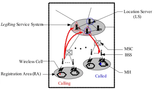
4.3.1 Local Query
A local query occurs when the calling and called MH are in the same LSN. Fig.
4-4 shows the local query path between two MHs. The procedure is described in the following steps:
The calling MH sends a QUERY message through the current MSC which forwards this message to all the LSs in randomly selected quorum from the Q-set of the local LegRing service system.
Upon receiving the QUERY message, the LS, which has a copy of queried
information, sends a REPLY containing the timestamp associated with the queried information. Otherwise, the LS sends a NULL reply.
When all the REPLY messages from all the LSs in the quorum are received, the procedure selects the location information with the latest timestamp. Since the calling and called hosts are in the same LSN, at least one of the LSs in the query quorum of local LSN has the location information of called MH. Then, according to the location information, the call can be connected to the intended MH.
If the procedure does not receive all the REPLY messages after a given period of time, then it randomly selects another query quorum, sends the QUERY message
LegRing Service System
BSS MSC
Registration Area (RA) MH
LegRing Service Network (LSN) Wireless Cell
Location Server (LS)
Query path in the local LSN Called Calling
Fig. 4-4. Local query.
to all the LSs in the new quorum again and goes to the previous step; otherwise, it stops.
The completion of local query procedure is quick, since it is done locally.
Compared to the query in the IS-41 scheme, which accesses the HLR that may be far away from the calling MH, our local query is more time effective since the access to HLR could involve two long-distance legs.
4.3.2 Remote Query
If the calling and called host are in different LSNs, the communication invokes the remote query procedure. Fig. 4-5 shows the remote query path between two MHs.
The procedure is described as follows:
The calling MH sends a QUERY message through the current MSC, which forwards this message to all the LSs in randomly selected quorum from the Q-set of the local LegRing service system.
Upon receiving the QUERY message, the LS of the local LSN, which has a copy of the queried information, sends a REPLY containing the timestamp associated with the queried information. Otherwise, the LS sends a NULL reply.
When all the REPLY messages from all the LSs of local LSN are received, the procedure selects the message with the latest timestamp. Since the called MH is at remote LSN, the REPLY message that has the latest timestamp would contain the redirected pointer. Then, according to the pointer information, the redirected request is sent to all the LSs in randomly selected quorum of the remote LSN.
If the procedure does not receive all the REPLY messages from local LSN after a given period of time, then it randomly selects another query quorum of local LSN, sends the QUERY message to all the LSs in the new quorum again, and goes to the previous step; otherwise, it goes to next step.
Upon receiving a QUERY message, the LS of remote LSN, which has a copy of queried information, sends a REPLY containing the timestamp associated with the queried information. Otherwise, the LS sends a NULL reply.
When all the REPLY messages from all the LSs of remote LSN are received, the procedure selects the location information with the latest timestamp. Then, according to the location information, the call request to the called MH can be connected
If the procedure does not receive all the REPLY messages from remote LSN after a given period of time, then it randomly selects another query quorum of the remote LSN, sends the QUERY message to all the LSs in the new quorum again, and goes to the previous step; otherwise, it stops.
Compared to the centralized IS-41, our query approach-- not only local query but also remote query-- yields better connection establishment delay. In our approach, there is no tromboning problem or triangular routing [22] as in centralize IS-41.
Consider the situation of a roaming MH h. Subscriber h’s HLR is in Seattle, WA, and h is currently roaming in the Boston, MA, area. Assume that a user k in Cambridge, which is a suburb of Boston, dials the number of h to set up a call, This call involves two long-distance legs, one between Cambridge and Seattle, and the other between Seattle and Boston.
LegRing Service System BSSMSC Registration Area (RA)MH LegRing Service Network (local LSN)LegRing Service Network (remote LSN)
Wireless Cell
Location Server (LS) Remote query path
Called Calling Fig. 4-5. Remote query .
Take a system with three LSNs as an example. Assume each LSN has four location servers (LSs) in its LegRing service system. According to Definition 4, the U-set and Q-set are constructed as follows:
In LSN1, the U-set and Q-set are
U-set={{0,1},{1,2},{2,3},{3,0}};
Q-set={{0,2},{1,3},{2,0},{3,1}};
In LSN2, the U-set and Q-set are
U-set={{4,5},{5,6},{6,7},{7,4}};
Q-set={{4,6},{5,7},{6,4},{7,5}};
In LSN3, the U-set and Q-set are
U-set={{8,9},{9,10},{10,11},{11,8}};
Q-set={{8,10},{9,11},{10,8},{11,9}};
If a mobile host h moves from one RA to another in the same LSN (LSN1), new location information should be stored in the local LSs, for example, server 2 and 3, in the randomly selected U-quorum of LSN1. When a mobile host h’ in LSN1 wants to communicate with host h, it can acquire the information from the other LSs, for example, server 0 and 2, in the randomly selected Q-quorum of LSN1. Since quorum {2,3} and {0,2} have the common server 2, the newest location information of host h can be extracted through the server 2.
If a mobile host g moves from LSN1 to LSN3, new location information should be stored in the local LSs of LSN3, for example, server 9 and 10, then the redirected pointer is disseminated to the remote LSs of LSN2, for example, server 5 and 6, and the remote LSs of LSN1, for example, server 3 and 0. When a mobile host g’ in
LSN2 wants to communicate with host g, it can require the information from the local LSs in Q-quorum of LSN2, for example server 7 and 5. Since quorum {5,6}
and {7,5} have the common server 5, the newest redirected pointer of host g can be extracted through the server 5. With this pointer, the query can be redirected to require the LSs of LSN3, for example, server 11 and 9. Since quorum {9,10} and {11,9} have the common server 9, the newest location information of host g can be extracted through the server 9.
4.4 Analytic Model
Fluid-flow Model is used as a user mobility model in our analysis. Under the fluid-flow model [40], the direction of an MH’s movement with respect to the border is uniformly distributed in the range of (0,2π) and the density of users is uniform throughout the area. Let v be an MH’s average speed; A and L will be the area and the perimeter of a given area, respectively. The border-crossing rate out of a given area for a single moving user is given by
(1)
We assume the shape of an RA in our LSN is circular, and then the border-crossing rate for an MH out of an RA is
(2)
The border-crossing rate for an MH out of an LSN is 2 .
rRA
v
= ⋅ ε π
A. L E v
⋅
= ⋅ π
(3)
where rRA and rLSN are the radius of circular area of the RA and LSN, respectively.
An MH that crosses an LSN will also cross an RA border. Hence, the border-crossing rate for the MH which stays in the same LSN is
(4)
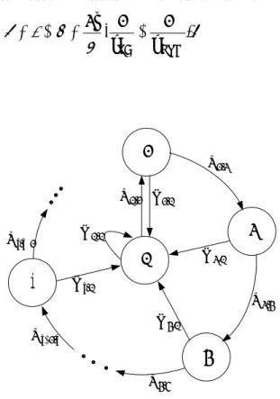
We use an imbedded Markov chain model to describe the location update process of an MH. The state transition diagram for the imbedded Markov chain is given in
0 1
2
3
i
0 ,
U0
1 ,
X0
2 ,
X1
3 ,
X2 i
Xi−1, 1 ,i+
Xi
0 ,
U1
0 .
U2 0
,
Ui
4 ,
X3 0 .
U3
Fig. 4-6. The state diagram of the imbedded Markov chain.
2 , rLSN
v
= ⋅ µ π
1 ).
( 1 2
LSN
RA r
r
v −
=
−
=ε µ π
ξ
Fig. 4-6. The resulting state probability of the analysis of this model is similar to [39].
The state of the imbedded Markov chain, k, is defined as the number of RAs in the same LSN, which the MH has passed by. The state transition rate Xk,k+1=ξ(0 ≤ k) represents the MH moving rate from state k to the state k+1, which moves to the neighbor RA in the same LSN. And the transition rate Ui,0 =μ(0 ≤ i) represents the MH moving rate from state i to state 0, which moves to another RA out of LSN.
Assume pk to be the equilibrium probability of being in state k of the process. We have
(5)
(6)
The sum of probabilities of all states is equal to one. Hence, we have
(7)
Using the equation (5), (6), and (7), we obtain
(8)
(9)
Based on this analytic model, we will analyze both the latency and cost for the LSN scheme and basic IS-41 HLR/VLR scheme in the following sections.
, ...) ...
( )
( 0 1 2
0 ξ +µ = p + p + p + + pk + µ
p
. 1
0
∑
∞ == k pk
LSN RA
r
p = r
= + µ ξ
µ
0
0 0
0 (1 )
)]
/(
[ p p p
pk = ξ ξ +µ k = − k . 1 )
1 p ( k
pk−ξ = k ξ +µ ≤
We introduce parameters for analyses in the following:
tl , δl: latency and cost for transmitting a message through the local link within the LSN.
tr , δr: latency and cost for transmitting a message through the remote link to another LSN.
tLS , δLS: latency and cost for a query or an update to the LS.
tV , δV: latency and cost for a query or an update to the VLR.
tH , δH: latency and cost for a query or an update to the HLR.
tlocal , δlocal: latency and cost of local location update (within LSN).
tremote , δremote: latency and cost of remote location update (across LSN).
4.5 Latency Analysis for LSN
4.5.1 Update Latency
In this section, we will analyze the average update latency for our LSN scheme.
The update latency is divided into two parts: local update latency (the time for an update procedure when the MH moves within LSN) and remote update latency (the time for an update procedure when the MH roams to another LSN).
The update request routing from the MSC to the Local LS is within the same LSN, which has a latency tl. Furthermore, the latency for an update to the database of the LS is tLS. Although a number of databases of the LSs are updated, they are carried out in parallel. In addition, there is an ACK message sent back, which also has a latency tl. Hence, we have a local update latency equation
. (10)
In contrast to the local update procedure, the remote update procedure must transmit update messages through the local and remote links concurrently since the MH roams to another LSN. Therefore, two remote routing latencies 2tr (one is the request, the other is the ACK) and an access latency tLS of the database of the remote LS are counted. Notice that the local and remote update requests are carried out in parallel (that is, only the long latency tr needs to be counted). Then we have
. (11)
Based on the equation (10) and (11), the average update latency of LSN is
(12)
4.5.2 Query Latency
In this section, we will calculate the query latency for LSN, which is associated with the hit ratio. Let h be a local LS hit ratio, thit and tmiss will be the query latencies of the protocols when there is a hit query (which means the location information is found in local LSN) and a miss query, respectively. The query request in hit case routing from the MSC to the Local LS is within the same LSN, which has a request latency tl. Furthermore, the latency for an access to the database of the LS is tLS. In addition, there is an ACK message sent back, which also has a latency tl. Hence, in a hit case, we have a query latency equation
. 2r LS
remote t t
t = +
. 2l LS
local t t
t = +
).
(
1
0
∑
∞=
+
=
k k
local remote
update P t t kP
T
(13)
In the miss case, the query procedure needs to transmit messages through the remote links to query the remote servers for the location information. Therefore, there are two additional remote request latencies 2tr and an access latency tLS of the database of the remote LS. Thus, we have a query latency equation of a miss case
(14)
Based on our query procedures discussed in section 4.3, the average query latency Tquery is given by
(15)
From equations (13) to (15), the average query latency Tquery is calculated as follows
(16)
4.6 Latency Analysis for IS-41
4.6.1 Update Latency
In the IS-41 scheme, the update message is forwarded to the MH’s HLR from the MH’s MSC to update its current location; and the remove message is issued from HLR to the old VLR to delete the obsolete location information. Next, the remove
. 2l LS
hit t t
t = +
. ) 1
( miss
hit
query ht h t
T = + −
. 2 2
2l r LS
miss t t t
t = + +
) 2 2 2 )(
1 ( ) 2
( l LS l r LS
query h t t h t t t
T = + + − + +
).
2 ( ) 2 2 2
( tl + tr + tLS −h tr +tLS
=
response message is sent back to the HLR, and the ACK message is then sent to the MH’s MSC. Thus the expression of Tupdate' is
(17)
4.6.2 Query Latency
In the IS-41 approach, a query message is transmitted to the called MH’s HLR to acquire the called MH’s location information. Then, the location information is sent to the calling MSC by the MH’s HLR. Therefore, the query latency equation for IS-41 is
(18)
In the following sections, the costs for our LSN scheme and IS-41 scheme are analyzed and compared. Again, we apply the same analytic model that was used in the latency analysis.
4.7 Cost Analysis for LSN
In this section, we analyze the cost for our LSN scheme. In our system, we assume that the number of LSNs is N and each LSN has m LSs.
4.7.1 Update Cost
Similar to the latency analysis discussed in Section 4.5.1, the update procedure is also divided into two parts: local update and remote update.
).
)(
2 4 (
1 0
∑
∞=
+ +
+
′ =
k k H
V r
update t t t P kP
T
.
2 r V H
query t t t
T′ = + +
In local update, a request signal transmitted from the MSC to the Local LSs is within the same LSN, which has a cost δl. In addition, there are m databases of LSs that are updated, where the access cost for each LS isδLS. Furthermore, the ACK message is transmitted in the local link, which also has a costδl. Hence, we have this local update cost equation
(19)
In remote update, there are additional request costs for transmitting signals on (N-1) remote links, which has a costδr for each link. In addition, m LSs are updated in each LSN. Thus, the remote update cost is
(20)
Based on the equation (19) and (20), the average update cost of LSN is
(21)
Let αu be an independent and identically distributed random variable representing the RA resident time; and we assume αu to be exponentially distributed with the rate of λU. Thus, the average update cost per unit time is
(22)
4.7.2 Query Cost
. )
1 ( 2
2 l r LS
remote δ N δ N mδ
δ = + − +
.
2 l LS
local δ mδ
δ = +
0
1
( ).
Update remote local k
k
P kP
δ δ δ ∞
=
= +
∑
U.
Update
CU =δ λ
Similar to Section 4.5.2, the h is assumed to be a local LS hit ratio. Let δhit and δmiss be the query costs of the protocols when there is a hit query and a miss query, respectively.
In addition to the cost δl for sending a message through the local link, there are m databases of LSs to be queried, where the cost is δLS for each LS. Hence, in a hit case, we have a query cost equation
(23)
In the case of a miss, the remote LSs of the redirected LSN are queried.
Therefore, an additional cost for sending a message through the remote link and costs for access to the databases of the remote LSs are needed, which have costs δr
and mδLS, respectively.
(24)
The average query costδQuery is then given by
(25)
Let αq be an independent and identically distributed random variable representing the call arrival time; and we assume αq to be exponentially distributed with the rate of λQ. Thus, the average update cost per unit time is
(26)
miss hit
Query hδ h δ
δ = +(1− )
.
2 l LS
hit δ mδ
δ = +
. 2
2
2 l r LS
miss δ δ mδ
δ = + +
Q.
Query
CQ =δ λ
).
2 ( ) 2
2 2 (
) 2
2 2 )(
1 ( ) 2
(
LS r
LS r
l
LS r
l LS
l
m h
m
m h
m h
δ δ
δ δ
δ
δ δ
δ δ
δ
+
− +
+
=
+ +
− + +
=
The total cost per unit time for our LSN scheme is
(27)
4.8 Cost Analysis for IS-41
The analyses of cost and latency for IS-41 are similar. We could substitute the cost variables for latency variables discussed in Section 4.6. Thus, the average update cost for IS-41 is
(28)
The average update cost per unit time for IS-41 is
(29)
The average query cost for IS-41 is
(30)
The average query cost per unit time for IS-41 is
(31)
The total cost per unit time for IS-41 scheme is ).
)(
2 4 (
1 0
∑
∞=
+ +
+
′ =
k k H
V r
Update δ δ δ P kP
δ
.
2 r V H
Query δ δ δ
δ′ = + +
U.
Update
CU′ =δ′ λ
Q.
Query
CQ′ =δ′ λ
Q.
U
LSN C C
C = +
(32)
4.9 Numerical Results and Discussion
The evaluations and comparisons of the latency and cost for the proposed LSN scheme and conventional IS-41 scheme are presented in this section. We normalize the value of tl and δl as to one for evaluating the latency and cost, respectively. The value of the cost ratio of δl / δr = 1/5 [39] is used. Further, we assume the cost ratio of δV / δLS = 1/3.5 and δLS / δH= 1/2. Similar to the assumption of cost ratio, the time ratio of tl / tr = 1/5, tV / tLS =1/3.5, and tV / tH = 1/2. It is also assumed that the whole system covers 100 LegRing service networks and each LegRing service system includes four location servers. In [41], the relation between the hit ratio and call to mobility ratio was calculated as
(33)
Moreover, the call to mobility ratio (CMR) can be expressed as the ratio of the call arrival rate to the mobility rate, which was stated in [39] and [42], such as
(34)
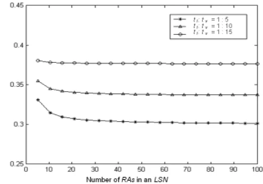
In Fig. 4-7, we show the average update latency between our LSN scheme and IS-41 under various numbers of RAs in one LegRing service network. The hit ratio h=0.8 is assumed. Three data sets are considered when t / t = 1/5, 1/10, and 1/15.
41 U Q.
IS C C
C = ′ + ′
. / U CMR=λQ λ
).
1 /( h h
CMR= −
According to the state probability P0, the MH mostly moves within one LSN, and therefore the remote updates are fewer. Since most updates are done locally in parallel, the average update latency of our scheme is less than that of IS-41. The less average update latency we get, the more quality of service (QoS) we receive.
Fig. 4-7. Comparisons of average update latency under various RAs.
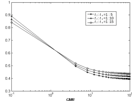
Fig. 4-8 shows the relation between call to mobility ratio and average query latency for two schemes. It is assumed that there are 75 RAs in one LegRing service network. This figure indicates that by using our scheme the query latency is reduced, since most local (hit case) queries are quickly processed or just as quickly redirected
to remote location servers to get location information. This figure illustrates the more CMR ratio we have, the less query latency we get. For example, when CMR = 5, the query latency of ours is about 50% less than that of IS-41.
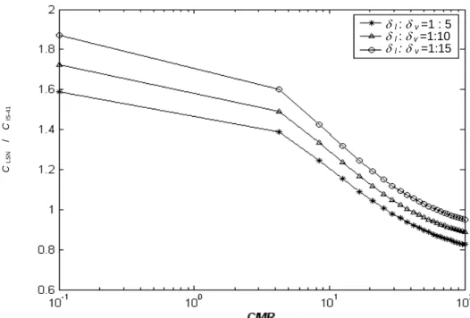
In Fig. 4-9, the total cost of update and query is compared between two schemes under the call to mobility ratio. Three data sets, δl : δr = 1:5, δl : δr = 1:10, and δl : δr = 1:15, are considered. In this comparison, when the CMR is higher than 20, our scheme has a lower cost than IS-41. Although, in some values of CMR, our scheme has a higher cost than IS-41, we still achieve two desirable results. First, our new scheme adds a fault tolerant approach. Second, in all cases our scheme has very lower latency and thus achieves a better quality of service (QoS).
Tquery (LSN) / T ’ query (IS-41)
t l : t v =1 : 5 t l : t v =1 :10 t l : t v =1 :15
Fig. 4-8. Comparisons of average query latency under various CMR.
C LSN / C IS-41
δl :δv =1 : 5 δl : δ v =1:10 δl : δv =1:15
Fig. 4-9. Comparisons of total cost under various CMR.