Pattern Recognition Letters
ELSEVIER Pattern Recognition Letters 16 ( 1995 ) 67-75
Improving block truncation coding by line and edge information and adaptive bit plane selection
for gray-scale image compression
Chen-Kuei Yang ~, Wen-Hsiang Tsai *
Department of Computer and lnformation Science, National Chiao Tung University, Hsinchu, Taiwan 300, ROC Received 16 February 1994; revised 2 August 1994
Abstract
A new approach to improving block truncation coding for gray-scale image compression is proposed. A set of line and edge bit planes is defined independently of input images and adaptively selected to yield lower bit rates and better reconstructed image quality.
Keywords: Block truncation coding; Image compression; Gray-scale image; Adaptive bit plane selection
1. Introduction
The block truncation coding (BTC) algorithm de- veloped by Delp and Mitchell (1979) is a two-level nonparametric quantizer whose output levels are ob- tained by preserving the first- and second-order mo- ments of input samples. According to the moment- preserving principle, other coding algorithms for im- proving the performance of the BTC algorithm have also been proposed (Halverson et al., 1982; Lema and Mitchell, 1984; Hui, 1990). These methods can be employed to compress an input image with less dis- tortion than the original BTC method. Udpikar and Raina (1987) developed a method, which applies vector quantization to BTC results, to truncate the This work was supported partially by National Science Coun- cil, Republic of China under Grant NSC83-0408-E009-010.
* Corresponding author. Email: [email protected] Also with the Department of Information Management, Ming Chuan College, Taipei.
bit plane or the mean vector, or both. Zeng and Neuvo (1993) developed another method which subsam- pies the BTC bit plane and uses the median filter as the interpolator. These methods improve the bit rate but introduce distortion into the reconstructed image and need additional computational load.
In the conventional BTC algorithm, an input im- age is partitioned into 4 X 4 blocks, and each block is coded individually. For each pixel with gray-value xi in a certain block with i = 1, 2, ..., m, there is an out- put value a or b computed by
a = X - # N / m q q f o r x , < X , (1)
b = ~ + # ~ for xi>~X (2)
where Y is the sample mean and #the standard devia- tion of all the gray-values of the block, that is,
0167-8655/95/$09.50 © 1995 Elsevier Science B.V. All rights reserved SSDI 0167-8655 ( 94 ) 00068-9
68 C.-K. Yang, W.-H. Tsai / Pattern Recognition Letters 16 (1995) 67-75
~'= - - x ~ , ( 3 )
m i = l
a = ~ (x, -.~) 2 (4)
i 1
with m being the total number of pixels in the block, and q the number of pixels with gray-values greater than or equal to )L
Each block is coded by the values of the mean and the standard deviation, or a and b, together with a 4X4 bit plane consisting of l's and O's indicating whether the pixels are quantized to a or b. Assigning 8 bits to each of a and b results in a bit rate of 2 bits/
pixel. To obtain higher compression ratios without increasing computational expenses, it is better to take into account the properties of the human visual sys- tem. Certain low-level aspects of vision can be accu- rately modeled. Some well-known psychophysical and physiological properties of the human visual system have been utilized in the design of certain coding al- gorithms. For example, it was found that the human eye assigns different attentions to the low- and high- frequency components of images, and this fact leads to the development of the subband coding algorithms (Forchheimer and Kronander, 1987; Chen and Hsing, 1991 ).
Decomposition of images into low-frequency blocks and blocks containing visually important features (such as edges or lines) suggests visual continuity and visual discontinuity constraints. A block is visually continuous if the values of all the pixels in the block are almost the same. On the contrary, if the varia- tions of the pixel values in the block are noticeable, it is a visually discontinuous block. The mean of a vis- ually continuous block is enough to represent the block. If a block is visually discontinuous and if a strong orientation is associated with it, then it should be coded as a kind of visually important feature
(Chen and Bovik, 1990) like edge or line.
The BTC algorithm uses a one-bit quantizer to adapt the local properties of the image. The bit planes occupy more than 61% of the output code. A new method for gray-scale image compression using pre- defined line and edge bit planes to improve the BTC method is proposed. A set of line and edge bit planes is defined according to the visual continuity and dis- continuity constraints. The line and edge bit planes
are defined independently of the images to be coded.
For each input image block, the proposed method follows the steps of the conventional BTC algorithm until a bit plane is generated. Then the bit plane is matched with the predefined bit planes. This results in a best-match predefined bit plane. The set of all the best-match predefined bit planes (each corre- sponding to an input image block) is classified and those types which occur more frequently in the set are picked out. Assume that n types of predefined bit planes are selected. Then, each of the original bit planes of the input image blocks is matched once again with the selected n predefined bit planes. Each block is finally coded by the values of the mean, the standard deviation, and the index of the best-match predefined bit plane. Experimental results show that the proposed approach is effective for gray-scale im- age compression.
Advantages of the proposed method include at least the following.
( 1 ) The method is based on the visual continuity and discontinuity constraints found in the human visual system which leads to the reasonable assump- tion that only edge and line patterns exist in small discontinuous image blocks. And due to the use of edge and line bit planes whose number is much smaller (64 in our study), 4 × 4 bit planes produced by BTC can be coded by indices with at most 6 bits instead of 16 bits.
(2) By selecting out only those predefined bit planes which occur more frequently and rematching them with the input bit plane, it requires even fewer bits to code the input bit plane without sacrificing too much quality in the reconstructed image. The bit rate is about 1 bit/pixel for 4X4 blocks if all the sixty- four predefined types of bit planes are used, and about 0.8125 bit/pixel for 4 X 4 blocks if only eight types of the predefined bit planes are used.
(3) By controlling the number n of the selected types of predefined bit planes which occur more fre- quently, adaptation to the input image can be achieved both in preserving reconstructed image quality and gaining reasonable bit rates.
The remainder of this paper is organized as fol- lows. The proposed line and edge bit planes are de- fined in Section 2. In Section 3, the adaptive bit plane selection scheme to select the n types of more fre- quently used bit planes is described. Several experi-
mental results shown to support the feasibility of the proposed method and some discussions are included in Section 4. Finally, some conclusions and sugges- tions for future study are made in Section 5.
visible errors, leading to the idea of adaptive bit plane selection described in detail in the next section.
3. Adaptive bit plane selection 2. Design of line and edge bit planes
With each visual bit plane representing a possible image block content, the number of possible bit planes increases exponentially with the block size. There- fore, a small block size must be selected for designing the desired line and edge bit planes. On the other hand, the line and edge bit planes proposed for use in this study basically are derived from the idea of the twelve types of line edges in a block mentioned in (Ferng and Tsai, 1992). According to the concept of visual discontinuity, it is assumed that the variation of the pixel values in a 4 × 4 block is noticeable only when there exist at least three or more pixels which form a neighborhood and show a shape of edge or line. Accordingly, sixty-four types of line and edge bit planes for 4 × 4 blocks are designed and shown in Fig.
1.
Because the ratio of the uniform bit planes to the non-uniform ones in a normal gray-scale image is usually small enough to be ignored and some prede- fined bit planes may have lower activity in certain images, the number of used predefined bit planes for each input image can be reduced further and adap- tively in practical applications without introducing
1100 1111 1100 1111 1111 0011 0011 1100 1100 1111 l l t 0 1111 1111 0111 0111 1110
11o0 oooo llli 111o o111 1111 111o o111 11oo oooo 1111 11oo OOll 1111 110o OOll
(1) (3) (5) (7) (9) (11) (13) (15)
0000 0111 1111 11t0 1111 0001 1000 1111 1111 0111 1111 1110 0111 0011 1100 1110 1111 0111 1111 1110 0011 0111 l l l 0 1100 1111 0111 0000 1110 0001 1111 1111 1000 (17) (19) (21) (23) (25) (27) (29) (31) lOll llO1 l l l l l l l l 0000 lO01 0000 lOlO lOll IlOl 0000 l l l l l l l l lO01 l l l l lOlO 1011 1101 1111 0000 1111 1001 0000 1010
lOll 11Ol 1111 1111 0000 1001 llll 1010
(33) (35) (37) (39) (41) (43) (45) (47)
11oo OOll lOOO OOOl lOOO OOOl 1o01 oooo
0110 0110 llO0 0011 0100 0010 0110 0000 0011 1100 0110 0110 0010 O 1 0 0 0110 0000 0001 lO00 0011 1100 O001 1000 1 0 0 1 0000 (49) (51) (53) (55) (57) (59) (61) (63) Fig. 1. Sixty-four types of line
sions not s h o w n ) .
and edge bit planes (reverse ver-
Basically, the sixty-four types of line and edge bit planes for 4 X 4 image blocks can be classified into three groups based on the amount of activity inside the image:
( 1 ) low-activity bit planes which include features like thin line with low frequency to appear in normal gray-scale images;
(2) medium-activity bit planes which contain smooth contrast edges;
(3) high-activity bit planes which contain basic line and edge patterns appearing most frequently in images.
In order to code the blocks efficiently and keep the high-activity bit planes in use, we adopt an adaptive bit plane selection algorithm described as follows.
Algorithm Adaptive Bit Plane Selection (ABPS) Step 1. Read in an M × Ngray-scale image G.
Step 2. Partition G into nonoverlapping 4 X 4 blocks
6.
Step 3. For each block Fj, perform the following steps of "initial matching":( 1 ) perform BTC to generate the mean 2j, the stan- dard deviation ~j, and the bit plane bj;
(2) match by with the sixty-four predefined line and edge bit planes;
(3) randomly choose one of the best matches if there is more than one best match, and let ij be the index of the best-match predefined bit plane;
(4) increment by one the value of a counter cij cor- responding to index i~, which indicates the activity of the best-match bit plane with index ij in the input image;
( 5 ) quantize Yj to 6 bits and ~ to 4 bits (Delp and Mitchell, 1979);
(6) store Y;, 8j, and bj in an array S.
Step 4. Sort all the values of the counters in the de- creasing order.
Step 5. Select the bit planes whose corresponding counter values are the top n largest (i.e., which ap- pear more frequently in the input image) and store them in an array BP.
70 C.-K. Yang, W.-H. Tsai / Pattern Recognition Letters 16 (1995) 67-75 Step 6. For each element bj in S, perform the follow-
ing steps of"rematching":
( 1 ) match bj with the n bit planes stored in BP;
(2) randomly choose one of best matches if there is more than one best match;
(3) output the xj, trj, and the corresponding index ij of the best match (note that index ij may be differ- ent from index ij found in Step 3 ( 3 ) ) .
The selection of the best-match predefined bit plane in Steps 3 and 6 above is based on template matching using the smallest number of different pixel values as the dissimilarity measure. This measure can be used to select easily the best-match predefined bit plane without causing too much visual difference accord- ing to our experimental experience. One reason for this is that the sixty-four predefined bit planes cover most visually obvious patterns existing in a 4 X 4 pixel block, and so the selection of the best-match bit plane to replace the input image block using the proposed measure will not produce too many changes of bit values.
The reconstruction procedure is the same as the conventional BTC. Because we use the index of the best-match predefined bit plane instead of the origi- nal bit plane as the output, we can use 6-bit indices instead of 16-bit bit planes. We can so reduce further the number of used bits when n < 64 where n is men- tioned in Step 5 in the above algorithm.
The overall bit rate can be computed as follows:
rn+s+A
R = 1 ~ (5)
where m is the number of bits used for the sample mean, s the number of bits used for the standard de-
viation, and A the number of bits used for indexing the selected n bit planes. For example, for m = 6, s = 4, and A=4, the bit rate R is 0.875 bit/pixel. Note that A=Flog2n7 where F7 means the "ceiling" of a real number.
Because the sixty-four 16-bit bit planes are prede- fined and fixed, they can be provided in advance at both the sender and the receiver ends. Therefore, it is unnecessary to include the number of bits used for storing the n bit planes in the overall bit rate com- puted by Eq. (5). Instead, only the bits used to index the selected n bit planes are needed, whose number is specified by A in Eq. ( 5 ).
4. Experimental results and discussions
The proposed approach has been tested on an IRIS Indigo workstation on several gray:scale images. Each gray-scale image has 8 bits/pixel and is 512 X 512 in size. To evaluate the performance of the proposed approach, we use a new criterion in this study, called the average bit plane assignment error (ABPAE), which is described in the following. For convenience of illustration, first define the bit difference of an in- put image block ~ as follows:
4 4
B D j = ~ ~ I b j ( x , y ) - b j ( x , y ) [ (6)
x = l y = l
where bj(x, y) is the value of the bit plane generated for Fj by the proposed method ABPS at (x, y) and bj(x, y) the value of the bit plane generated for ~ by the BTC method at (x, y). Then, the bit plane assign- ment error o f ~ is defined as follows:
Table 1
The ABPAE values and bit rates of applying the conventional BTC and the proposed ABPS to some images using 64, 32, 16, and 8 predefined bit planes
Image name A B C D E
8 bit planes 16 bit planes 32 bit planes 64 bit p l a n e s conventional BTC
Lenna 0.363 0.249 0.145 0.047 0.000
pepper 0.427 0.322 0.194 0.084 0.000
jet 0.427 0.322 0.096 0.021 0.000
mandrill 0.435 0.287 0.162 0.040 0.000
candy 0.202 0.001 0.000 0.000 0.000
house 0.144 0.000 0.000 0,000 0.000
bit rate 0.8125 b/pixel 0.875 b/pixel 0.9375 b/pixel 1 b/pixel 2 b/pixel
Table 2
The MAE values and bit rates of applying the conventional BTC and the method ABPS to some images using 64, 32, bit planes
16, and 8 predefined
Image names A B C D E
8 bit planes 16 bit planes 32 bit planes 64 bit p l a n e s conventional BTC
Lenna 4.55 4.16 3.96 3.85 3.06
pepper 5.05 4.40 4.17 4.07 3.08
jet 4.77 4,19 3.88 3.82 3.07
mandrill 13.18 12.22 11.36 11.01 7.85
candy 2.25 1,63 1.55 1.55 1.20
house 2.26 1.79 1.79 1.79 1.49
bit rate 0.8125 b/pixel 0.875 b/pixel 0.9375 b/pixel 1 b/pixel 2 b/pixel
Fig. 2. The original images of"Lenna" left and "mandrill" right, both with size 512 × 512.
if.oj 4
otherwise. ( 7 )
According to our experimental results, we notice that two bit planes with their corresponding bit difference value less than 4 usually cannot be distinguished by the human vision system. Therefore, in (7) above, when BPAEj is set to 1, it means that the bit plane assignment is unsuitable because the bit difference value is larger than 4.
Finally, the ABPAE of an input image is defined as follows:
1 B
ABPAE-- ~ E BPAEj (8)
j = l
where B is the number of blocks in the input image.
A smaller value of the ABPAE means that the bit plane assignment causes fewer errors. Table 1 shows the ABPAE values of some experiments conducted on six images "Lenna", "pepper", "jet", "mandrill",
"candy", and "house" using 64, 32, 16, and 8 prede- fined bit planes (i.e., with the value of n mentioned
in Step 5 in Algorithm ABPS being 64, 32, 16, and 8). It can be seen that the ABPAE values of the col- umn of using the 64 predefined bit planes (Column D) are smaller than 0.084; that means the bit planes generated by the proposed method are visually al- most identical to the bit planes generated by the BTC method. However, from the last row of Table 1, it is seen that the compression ratio obtained from the proposed method using the 64 predefined bit planes is two times that of the BTC method. Also, it can be observed that for images with uniform regions like
"candy" and "house", the proposed method can both preserve the reconstructed image quality and gain reasonable compression ratios due to the adaptive se- lection of the n predefined bit planes (with n < 64) mentioned in Step 5 of Algorithm ABPS. That is, it requires fewer bits to code the selected bit planes without sacrificing too much quality in the recon- structed image.
We also use the mean absolute error (MAE) as an- other criterion to evaluate the quality of the recon- structed image. The MAE is defined as follows:
72 C.-K. Yang. W.-H. Tsai / Pattern Recognition Letters 16 (1995) 67-75
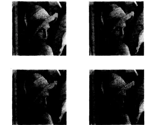
Fig. 3. The reconstructed "Lenna" using 64, 32, 16, and 8 predefined bit planes in to-left, top-right, bottom-left, and bottom-fight, respectively.
MAE= ~ - ~ 1 ~ I f l ( x , y ) - f e ( x , y ) l (9)
w h e r e M x N = 5 1 2 X 5 1 2 a n d f ~ ( x , y ) andf2(x, y) are the pixel gray-values of the reconstructed and origi- nal images, respectively, at image coordinates (x, y).
A smaller value of the MAE means that the recon- structed image is less distorted.
Table 2 shows the MAE values obtained from per- forming the proposed algorithm ABPS and the con- ventional BTC method on the above-mentioned im- ages using 64, 32, 16, and 8 predefined bit planes. It can be s e e n that the more used bit planes, the smaller the MAE values. For each image, there exists possi- bly an optimal number of bit planes that yields the highest compression ratio with visual quality still being kept reasonable in the reconstructed image.
Fig. 2 shows the original images of "Lenna" and
"mandrill" of size 512 × 512. Figs. 3 and 4 show the reconstructed images of"Lenna" and "mandrill", re- spectively, after using the ABPS as the compression algorithm. Each figure shown includes the recon-
structed images using 64, 32, 16, and 8 predefined bit planes in top-left, top-right, bottom-left, and bottom- right, respectively. Note that even when only 8 pre- defined bit planes are used (resulting in a good bit rate of 0.8125 ), the reconstructed image quality is still acceptable. This is due to the adaptive selection of fewer but more frequently occurring bit planes (see Step 6 of Algorithm ABPS). Only a few zigzag edges are noticeable which are due to the aliasing effect re- suiting from block truncation using two gray-levels for each block as well as the use of fewer bit planes.
Fig. 5 shows the "error images" of"Lenna" which includes the gray-value differences between the orig- inal and the reconstructed images using 64, 32, 16, and 8 predefined bit planes in top-left, top-right, bot- tom-left, and bottom-right, respectively. The errors are magnified five times since otherwise the pictures would be almost fully black. This means that the dif- ference values are very small. Also, the errors are dis- tributed in the images. These facts indicate that the p r o p o s e d approach is effective. As can be seen, the errors are distributed in the images especially on the
Fig. 4. The reconstructed "mandrill" using 64, 32, 16, and 8 predefined bit planes in top-left, top-right, bottom-left, and bottom-right, respectively.
line and edge locations.
In some cases, it is desired to yield automatically the number n of bit planes selected for use in re- matching (see Steps 5 and 6 of Algorithm ABPS) ac- cording to the distributions of the counter values ci mentioned in Step 3 (4) in ABPS. One way to achieve this is to insert an additional step between Step 4 and Step 5 of ABPS as follows:
Step 4.5. For automatic selection of the value of n, ( 1 ) set variables m = 0 and S u m = 0;
(2) let the sorted counters be indexed by i = 1 through 64 with i = 1 for the largest counter value;
(3) set i = 1;
(4) set S u m = S u m + c i ; (5) set m = m + 1;
(6) if the value o f S u m is smaller than 90% of the total number of the image blocks, then set i = i + 1 and go to (4), else go to ( 7 );
( 7 ) set n to 2 k, where k is such that 2 k- ~ < m < 2 k.
In Step 4.5 (6), when the value of S u m is larger than 90% of the total number of image blocks, it means
that 90% of the blocks will be rematched to identical predefined bit planes in Step 6 of ABPS, and the re- sulting value of the ABPAE may be kept smaller than 0.1 as can be seen from Column D of Table 1.
Table 3 shows the results of automatic selection of n by Step 4.5 of ABPS. It can be seen that forty-four to forty-nine bit planes are required when 90% of the image blocks are included, and the values of the AB- PAE are close to 0.1 except those of the images
"candy" and "house". This means that images with randomized image contents usually require sixty-four predefined bit planes if good quality of the recon- structed image is desired. However, images like
"candy" and "house", which have uniform regions, usually require fewer bits to represent the corre- sponding indices of the selected bit planes because the number of the selected bit planes is smaller.
Finally, it is mentioned that the idea of the pro- posed approach is only suitable for smaller blocks and not applicable for bigger blocks (8 × 8 blocks, for ex- ample). Applying the BTC method to bigger blocks will cause blocky artifacts to appear on the recon- structed image, and the same situation will appear
74 C.-K. Yang, W.-H. Tsai / Pattern Recognition Letters 16 (1995) 67-75
I
Fig. 5. The error images of "Lenna" of the reconstructed images using 64, 32, 16, and 8 predefined bit planes in top-left, top-right, bottom-left, and bottom-right, respectively, compared with the original image (five times the difference values).
Table 3
The value of n selected automatically by Step 4.5 of ABPS
Image 90% of blocks ABPAE m n
Lenna 14807 0.088 47 64
pepper 14805 0.096 48 64
jet 14773 0.055 44 64
mandrill 14749 0.075 49 64
candy 15151 0.010 15 16
house 14833 0.075 13 16
when the proposed approach is applied to bigger blocks.
the use of a set ofpredefined bit planes and an adap- tive bit plane selection scheme. Compression results with good bit rates and reasonable reconstructed im- age quality have been obtained. Compared with those methods (Udpikar and Raina, 1987; Zeng and Neuvo, 1993 ) using vector quantization, our method requires no training phase but still yields good qual- ity in reconstructed images. To lower the MAE val- ues, one of the methods of Halverson et al. (1982), Lema and Mitchell (1984) or Hui (1990) can be ap- plied. Also, the proposed method can be extended for color image compression and at least a 3 bits/pixel data rate can be achieved.
5. Conclusions and suggestions for future study References A new approach to improving the conventional
BTC has been proposed. The approach is based on
Chen, D. and A.C. Bovik (1990). Visual pattern image coding.
IEEE Trans. Commun. 38, 2137-2146.
Chen, C.T. and T.R. Hsing (1991). Digit coding technique for visual communications. J. Visual Communication and lmage Representation 2 ( 1 ), 1-16.
Delp, E.J. and O.R. Mitchell (1979 ). Image compression using block truncation coding. IEEE Trans. Commun. 27, 1335-
1342.
Ferng, S.Y. and W.H. Tsai (1992). Dynamic image compression using moment-preserving technique. Proc. 1992 National Symposium on Telecommunications, Taiwan, 190-195.
Forchheimer, R. and T. Kronander ( 1987 ). Image coding - from waveforms to animation. IEEE Trans. Acoust. Speech Signal Process. 37, 2008-2023.
Halverson, D.R., N.C. Griswold and G.L. Wise (1982). A
generalized block truncation coding algorithm for image compression. IEEE Trans. Acoust. Speech Signal Process. 32, 664-668.
Hui, L.H. (1990). An adaptive block truncation coding algorithm for image compression. Proc. IEEE Internat. Conf. Acoust.
Speech Signal Process., New Mexico, 2233-2236.
Lema, M.D. and O.R, Mitchell (1984). Absolute moment block truncation coding and its application to color images. IEEE Trans. Commun. 32, 1148-1157.
Udpikar, V. and J.P. Raina (1987). BTC image coding using vector quantization. IEEE Trans. Commun. 35, 352-356.
Zeng, B. and Y. Neuvo ( 1993 ). Interpolative BTC image coding with vector quantization. IEEE Trans. Commun. 41 (16),
1436-1438.


![[2015-Fall] WNFA lab1 - CamCom](data:image/gif;base64,R0lGODlhAQABAIAAAP///wAAACH5BAEAAAAALAAAAAABAAEAAAICRAEAOw==)