利用網版印刷碳膠電極表面改質方式研究葡萄糖生物感測器的改良
100
0
0
全文
(2) 摘要 我們以葡萄糖生物感測器為模型,探討了幾種碳膠電極的改質方式 來改善感測器的效能。首先,polypyrrole修飾的電極增加了對於葡萄 糖的敏感度,相對的偵測電流值增加許多;但是polypyrrole本身並無 法忍受高濃度的過氧化氫,過氧化氫會使polypyrrole氧化分解,導致 無法偵測電流隨著使用次數降低,而無法繼續使用。另一種使用濺鍍 方式,將鈀金屬沈積在電極表面上,此鈀金屬具有催化過氧化氫氧化 的特質;再利用PVA-SbQ光敏感性高分子將葡萄糖氧化脢包埋固定在 電極上,製作而成的生物感測器能偵測最低的濃度為 500 nM的葡萄 糖,檢測範圍為 500 nM 至 1000 µM (R2= 0.997),能長期保存三個月 以及再現性良好( 濃度為 10 µM, R.S.D = 4.7% , n=20)。最後,將濺鍍 上鈀金屬的電極再經過電漿化學蒸鍍處理賦予氨基在表面上,沈積上 去的氨基供給戊二醛橋接酵素和電極,進而將酵素固定在電極上。此 種作法由於酵素反應與電極表面極為接近,因此能得到快速的反應 (約五秒內) ,且此種製作感測器方式,能加以延伸至生物微機電製 程(BioMEMS)應用。. 2.
(3) Abstract We developed glucose biosensor fabricating by several modification on the carbon paste electrode. First, the polypyrrole-modified electrode showed increasing response for sensing glucose. However, the inherent character of Ppy could not stand to the oxidative damage of hydrogen peroxide leading to degradation of the electrode. Second, we took advantage of thin-film technology to palladinized electrode by sputtering. Palladium has an excellent property to catalyst the final target, H2O2. Incorporate with PVA-SbQ immobilizing glucose, the glucose sensor exhibited high sensitivity (detection limit of 500 nM for glucose), long-term stability (retaining activity for 3 months) and good reproducibility (R.S.D = 4.2 % for 10 µM glucose, n=20). Finally, we proposed a simple thin-film glucose biosensor based on a plasmapolymerized film. The amino group was deposited on the Pd-modified electrode so that there is a lot of available adherent site directly connect with the enzyme. Since the obtained film revealed a good interfacial design between enzyme and electrode surface, the rapid response time was achieved (~ 5sec). The most important is this design of biosensor is compatible for mass production in the filed of BioMEMS.. 3.
(4) Content Page Chinese abstract. 1. English abstract. 2. Content. 3. Introduction. 4. Ⅰ. Biosensor. 4. Ⅱ. Analytical electrochemistry. 6. Ⅲ. Interface of Biosensors. 14. Ⅳ. Fabrication of Working Electrodes. 17. Ⅴ. Experimental Purpose. 29. Material and method. 30. Result and Discussion. 34. Part Ⅰ.. 34. Part Ⅱ.. 40. Part Ⅲ.. 48. Reference. 53. Appendix. 86. 4.
(5) Introduction I. Biosensor Biosensor is based on the direct coupling of an immobilized biologically active material, such as protein, enzyme, antibody, cells or tissue, with a signal transducer and an electronics amplifier. The main function of a transducer is to convert the physical or chemical change in the biologically active material resulting from the interaction with the analyte into an electric signal (Shown in Appendix 1). Based on the type of transducer used, biosensors have been divided into optical, calorimetrical, piezoelectrical and electrochemical biosensors. All these biosensors suffer from certain drawbacks. For example, optical biosensors, though very sensitive, cannot be used in the turbid media. Thermal biosensors cannot be utilized in systems with very little heat change. Moreover, they are not easy to handle. Electrochemical biosensors have emerged as the most commonly used biosensors. They have been found to overcome most of the disadvantages, which inhibit the use of other types of biosensors, i.e., electrochemical biosensors are rapid, easy to handle and are of low cost.. I-1 Electrochemical Biosensors Electrochemical biosensors are the most commonly used type of biosensors. They work based on that the consuming or generating of electrochemical species such as electron, during a bioprocess. Subsequently, an electrochemical signal can be produced and measured by an electrochemical detector. Electrochemical biosensors are widely 5.
(6) accepted for biosensing owing to the fact that they can be operated in turbid media, have comparable instrumental sensitivity, and are easier to miniaturization. Depending on the electrochemical property to be measured by a detector system, electrochemical biosensors may further be divided into conductometric, potentiometric and amperometric biosensors.. I-1-1 Conductometric Biosensors Conductometric biosensors measure the changes in the conductance between a pair of metal electrodes as a consequence of the biological component (Sukeerthi et al, 1994). Contractor et al. have constructed biosensors for estimation of glucose and urea by monitoring the change in the electronic conductivity arising as a change in redox potential and/or pH of the microenvironment in the polymer matrix.. I-1-2 Potentiometric Biosensors Potentiometric biosensors measure the potentials produced at the working electrode during a biological with respect to the reference electrode (Senillolu et al., 1999). They work under equilibrium conditions and monitor the accumulation of charge on the working electrode at zero current due to the selective binding of electrochemical species on the electrode surface. Ion selective electrode, for example, detects ions such as Na+, K+, Ca2+, H+ or NH4+ in the complex biological matrices by sensing changes of the electrode potential when the ions bind to an appropriate ion exchange membrane.. 6.
(7) I-1-3Amperometric Biosensors Amperometric biosensors measure the changes in the current on the working electrode due to direct oxidation or reduction of the products of a biochemical reaction. Amperometric techniques are linearly dependent on the concentration of analyte and give a normal dynamic range and a response to errors in the measurement of current. Oxygen and H2O2, the co-substrate and the product of several enzymic reaction of oxidase are usually detected amperometrically (Lindgren et al., 2000). The electrochemical signal can be detected in mediated or unmediated electrochemical process for electron transfer. Ferrocene and its derivatives, ferricyanide, methylene blue, benzoquinone and N-methyl phenazine are most commonly used mediators in the designed of the mediated amperometric biosensors (Jaffari et al., 1997; Garjonyte et al., 2001). Conducting polymers such as polyaniline and polypyrrole have also been used for fabricating electrochemical biosensors (Schuhmann, 1995; Chaubey et al., 2000a,b).. II. Analytical electrochemistry II-1 Introduction of Electroanalysis Electroanalytical techniques are concerned with the interplay between electricity and chemistry, namely the measurements of electrical quantities, such as current, potential, or charge, and their relationship to chemical parameters. The two principle types of electroanalytical measurements are potentiometric and potentiostatic. Both types require at least two electrodes (conductors) and a contacting sample (electrolyte) solution, 7.
(8) which constitute the electrochemical cell. The electrode surface is thus a junction between an ionic conductor and an electronic conductor. One of the two electrodes responds to the target analyte and is thus termed the working electrode. The second one, termed the reference electrode, is of constant potential (that is independent of the properties of the solution). Electrochemical cells can be classified as electrolytic (when they consume electricity from an external source) or galvanic (if they are used to produce electrical energy). Potentiometry, which is of great practical importance, is a static (zero current) technique in which the information about the sample composition is obtained from measurement of the potential established across a membrane. Different types of membrane materials, possessing different ion-recognition processes, have been developed to increase selectivity. The resulting potentiometric probes have thus been widely used for several decades for direct monitoring of ionic species such as protons or calcium, fluoride, and potassium ions in complex samples. Controlled-potential (potentiostatic) techniques deal with the charge-tranfer processes at the electrode-solution interface, and are based on dynamic (no zero current) situations. Here, the electrode potential is used to derive an electron-transfer reaction and the resultant current is measured. The role of the potential is analogous to that of the wavelength in optical measurements. Such a controllable parameter can be viewed as ‘electron pressure’, which forces the chemical species to gain or lose an electron (reduction or oxidation, respectively).. II-2 Faradic Processes 8.
(9) The objective of controlled-potential electroanalytical experiments is to obtain a current response that is related to the concentration of the target analyte. This objective is accomplished by monitoring the transfer of electrons during the redox process of the analyte: -. O + ne. R. where O and R are the oxidized and reduced forms, respectively, of the redox couple. Such a reaction will occur in a potential region that makes the electron transfer thermodynamically or kinetically favorable. For systems controlled by the laws of thermodynamics, the potential of the electrode can be used to establish the concentration of the electroactive species at the surface [Co (0,t) and CR (0,t)] according to the Nernst equation: E = E0 + 2.3RT/nF log [CO (0,t)/ CR(0,t)] Where E0 is the standard potential for the redox reaction, R is the universal gas constant (8.314JK-1 mol-1), T is the Kelvin temperature, n is the number of electrons transferred in the reaction, and F is the Faraday constant (96,487 coulombs). On the negative side if E0, the oxidized from thus tends to be reduced, and the forward reaction (i.e., reduction) is more favorable. The current resulting from a change in oxidation state of the electroactive species is termed the faradic current because it obeys Faraday’s law (i.e. the reaction of 1 mole of substance involves a change of n × 96,487 coulombs). The faradic current is a direct measure of the rate of the redox reaction. The resulting current-potential plot, known as the voltammogram, is a display of current signal (vertical axis) versus the excitation potential (horizontal axis). The process involved in the 9.
(10) electrode reaction governs the exact shape and magnitude of the voltammetric response. The total current is the summation of the faradic currents for the sample and blank solutions, as well as the nonfaradic charging background current.. II-3 Mass Transport-Controlled Reactions Mass transport occurs by three different modes; diffusion, convection and migration. Diffusion is the spontaneous movement under the influence of concentration gradient (i.e., from regions of high concentration to regions of lower concentration), aimed at minimizing concentration differences. Convection allow substrate transport to the electrode by a gross physical movement; such as fluid flow occurs with stirring or flow of the solution and with rotation or vibration of the electrode (i.e., forced convection) or due to density gradients (i.e., natural convection). Migration is the movement of charged particles along an electrical field (i.e., the charge is carried through the solution by ions according to their transference number). The flux (J) is a common measure of the rate of mass transport at a fixed point. It is defined as the number of molecules penetrating a unit area of an imaginary plane in a unit of time, and has the units of mol cm-2 s-1. The current (i) is directly proportional to the flux (J), n is the charge of ion, F is the Faradic constant, A is the area of measurement: i=-nFAJ II-4 Reactions Controlled by the Rate of Electron Transfer 10.
(11) However, the current between electrodes is controlled by the rate of electron transfer (i.e., reaction with sufficiently fast mass transport). The current-potential relationship for such reactions is different from mass transport-controlled reactions. -. Consider the electron-transfer reaction: O + ne. R. The actual. electron transfer step involves transfer of the electron between the conduction band of the electrode and a molecular orbital of O or R (e.g., for a reduction, from the conduction band into an unoccupied orbital in O). The rate of the forward (reduction) reaction, Vf , is the first order in O: Vf = kfCo(0,t). (1). While that of the reversed (oxidation) reaction Vb, is the first order in R: Vb = kbCR(0,t). (2). Where kf and kb are the forward and backward heterogeneous rate constants, respectively. These rate constants depend upon the operating potential according to the following exponential relationship: kf =k0 exp[-αnF(E-E0)/RT]. (3). kb =k0exp[(1-α)nF(E-E0)/RT]. (4). where k0 is the standard heterogeneous rate constant, and α is the tranfer coefficient. The value of k0 (in cm s-1) reflects the reaction between the particular reactant and the electrode material used. The value of α ( between zero and unity) reflects the symmetry of the free energy curve (with respect to the reactants and products). For symmetric curve, α should be close to 0.5. Thus, α is a measure of the fraction of energy that is put into the system and actually used to lower the activation energy. In 11.
(12) conclusion, reaction equations (3) and (4) indicate that kf and kb can be influenced in an exponential fashions, respectively. For an oxidation, the energy of the electrons in the donor orbital of R must be equal to or higher than the energy of electrons in the electrode. For reduction, the energy of the electrons in the electrode must be higher than the energy of the electrons in the receptor orbital of R. Since the net reaction rate is: Vnet=Vf-Vb= kfCo(0,t)- kbCR(0,t). (5). and as the forward and backward currents are proportional to Vf and Vb, respectively, if = nFAVf. (6). ib = nFAVb. (7). the overall current is given by the difference between the currents due to the forward and backward reactions: inet = if - ib = nFA [kfCo(0,t)- kbCR(0,t)]. (8). By substituting the expressions for kf and kb (equation 3 and 4), one obtains inet = nFA k0 {Co(0,t)exp[-αnF(E-E0)/RT] - CR(0,t) exp[(1-α)nF(E-E0)/RT]}. (9). which describes the current-potential relationship for reactions controlled by the rate of electron transfer. Note that the net current depends on both the operating potential and the surface concentration of each form of the redox couple.. II-5 Cyclic Voltammetry 12.
(13) Cyclic voltammetry consists of scanning linearly the potential of a stationary working electrode (in an unstirred solution) using a triangular potential waveform (shown in appendix 8). Depending on the information sought, single or multiple cycles can be used. During the potential sweep, the potentiosatat measures the current resulting from the applied potential. The cyclic voltammograms is a complicated, time-dependent function of a large number of physical and chemical parameters. Appendix 8 illustrates the expected response of a reversible redox couple during a single potential cycle. It is assumed that only the oxidized from O is present initially. Thus, a negative-going potential scan is chosen for the first half-cycle, starting from a value where no reduction occurs. As the applied potential approaches the characteristic E0 for the redox process, a cathodic current begins to increase, until a peak is reached. During the reverse scan, R molecules (generated in the forward half cycle, and accumulated near the surface) are reoxidized back to O and an anodic peak results. The characteristic peaks in the cyclic voltammograms are caused by the information of the diffusion layer near the electrode surface. Appendix 9 illustrate four concentration gradients for the reactant and product at different times corresponding to (a) the initial potential value, (b) and (d) the formal potential of the couple (during the forward and reversed scans, respectively), and (c) to the achievement of a zero reactant surface concentration. Note that the continuous change in the surface concentration is coupled with an expansion of the diffusion layer thickness. The resulting current peaks thus reflect the continuous change of the concentration gradient with the time. Hence, the increase to the 13.
(14) peak current corresponds to the achievement of diffusion control, while the current drop (beyond the peak) exhibits a t–1/2dependence (independent of the applied potential). For the above reasons, The reversal current has the same shape as the forward one.. II-6 Three Electrode System The characteristic of modern voltammetric analyzers is the potentiostatic control of the working electrode, which minimizes errors from cell resistance (i.e., poorly defined voltammograms with lower current response and shifted and broadened peaks). Equation explains the cause for this ohmic distortion: Eapp = E w.e. –E r.e. – iR where iR is the ohmic potential drop. The potentiostatic control, aimed at compensating a major fraction of the cell resistance, is accomplished with a three-electrode system and a combination of operational amplifiers and feedback loops (As shown in appendix 10). Here, the reference electrode is placed as close as possible to the working electrode and is connected to the instrument through a high-resistance circuit that draws no current from it. Because the flow cannot occur through the reference electrode, a current-carrying auxiliary (counter) electrode is placed in the solution to complete the current path. Hence, the current flows through the solution between the working and the auxiliary electrodes. Symmetry in the placement of these electrodes is important for the assumption that the current paths from all points on the working electrode are equivalent. Because no current passed through the reference electrode and because of its position close to the working 14.
(15) electrode, the potential drop caused by the cell resistance (iR) is minimized. If the potential sensed by the reference electrode is less than the desired value, the operational amplifier current-to-voltage converter (called a ‘current follower’) to the working electrode, it is possible to measure the current without disturbing the controlled parameters. The instrument also includes a ramp generator to produce various regularly changing potential waveforms.. III. Interface of Biosensors III-1 Immobilization of Bioelements Almost all of the biological elements such as enzymes, receptors, antibodies, cells and tissues are less stable under normal condition. To extend the usage and lifetime of biological elements in the fabrication of biosensors, it is required to immobilize the biological elements in a suitable matrix. Thus, the activity of immobilized biolayer is largely affected by the physical and chemical properties of the surface or matrix, such as surface area, porosity, hydrophilicity of immobilizing surface or matrix and the methodology chosen for immobilization. A number of techniques, including physical adsorption, covalent coupling, cross-linking and entrapment, have been commonly used to immobilize biological elements on solid carriers as shown in table of appendix 2.. III-1-1 Physical Adsorption Physical adsorption of protein to solid support is by electrostatic, hydrophobic, hydrophilic and affinity interactions. Hydrophobic and 15.
(16) hydrophilic interactions of enzymes with membranelike layered assemblies, or electrostatic interactions between charged interfaces and proteins, can lead to organized, supramolecular layered protein interfaces. Electrostatic interactions combined with hydrophilic adhesion may lead to irreversible adsorption and alignment of proteins on monolayers terminated with carboxylic acids. Affinity interactions between an enzyme and its substrate, a receptor protein and its recognition pair, or antigen - antibody pairs are often characterized by high association constants of the resulting complexes, which has enabled the use of specific recognition interactions to construct protein layers on solid supports.. III-1-2 Covalent Bonding Covalent linkage of proteins to conductive or semiconductive supports often utilizes the availability of functional groups on the surface of the solid support. For example, metal-oxide materials such as TiO2, SnO2, contain surface hydroxyl groups that are synthetically useful for the coupling of organic materials. Noble metals (Au, Pt) were chemically or electrochemically pre-treated to generate such surface hydroxyl functions (Widrig et al., 1987). Carbon electrodes, after appropriate chemical treatment, contain different surface-associated functional groups (carboxylic, carbonyl, lactone, hydroxyl,etc.) capable of attachment to proteins. To control the surface density of functional groups on a graphite surface and their chemical activity, O2-plasma, strong oxidants, or electrochemical oxidation were applied. Amino functions were introduced onto graphite electrodes by their treatment with NH3-plasma 16.
(17) (as shown in Appendix 3). Carboxylic acid groups or amine functions, directly attached to the conducting support can be used for the covalent coupling of complementary amino groups on the lysine residues or carboxylic acid groups of aspartic/glutaric acid residues, respectively.. III-1-3 Cross-linking It is possible to immobilize enzyme using intra- or intermolecular cross-linking of enzyme molecules. This method is based on the formation of three-dimensional links between the biological material and bi- or multi- functional reagents. The resulting modified biological material is completely insoluble in water and can be adsorbed onto a solid surface. Glutaraldehyde is one of the cross-linking reagents most used amongst other multifunctional reagents. Configuration based on multiple –layer deposition using glutaraldehyde as a cross-linking agent for enzyme immobilization is one of the most reported methods for enzyme immobilization in planar biosensor devices. The resulting 3D network affects the enzymatic kinetic and diffusion characteristics. It should be optimized for each enzyme trying to enhance its immobilization and at the same time to preserve its activity as well as the appropriate diffusion characteristics.. III-1-4 Entrapment Entrapment within an adequate matrix can improve enzyme stability. Moreover, immobilization in matrices like gels, polymers, pastes, or inks can be as simple as physical adsorption. Generally, the biological material 17.
(18) is mixed and well homogenized with the supporting material and then applied over the electrode pad as an additional membrane that has to be dried or polymerized. Some of the matrices used are gelatins, polyurethanes, polyvinyl alcohol and carbon paste. The principal advantage of this technique is its compatibility with mass fabrication techniques. IV. Fabrication of Working Electrodes IV-1 Conducting polymer Conducting polymer is material that contain π-electron on the backbone which allows it to exhibit usual electronic properties such as electrical conductivity, low energy optical transitions, low ionization potential and high electron affinity. The conducting polymer consists of an extended π-conjugated system with alternating single and double bonds along the polymer chain. The characteristic of high electrical conductivity of these organic polymers leads to the name ‘synthetic metals’. Accordingly, conducting polymers are largely employed in the design and development of chemical and biochemical sensing devices. (Trojanowicz and vel Krawczyk, 1995; Situmorang et al., 1998; Bidan, 1992). Owing to their unusual electronic properties, conducting polymer has enhanced the function of conventional electrodes by providing new properties. Moreover, they are also applied in electrocatalysis, membrane separations and chromatography (Trojanowicz and vel Krawczyk, 1995). The mechanism of conduction in such polymers is very complex since such materials exhibit conductivities across a range of about fifteen 18.
(19) orders of magnitude and many involve different mechanisms within different regimes. The electrical conductivity of conducting fiber can be enhanced by several orders of magnitude through doping. The concepts of solitons, polarons and bipolarons have been used to explain the electronic phenomena in these polymers (Heeger, 1986). The conductivity of conducting polymers is influenced by a variety of factors including polaron length, the conjugation length, the overall chain length and the charge transfer to adjacent molecules (Kroschwitz, 1988). The indication hopping has been proposed to explain the conductivity of these polymers. The hopping of electrons between localized states can be assisted by lattice vibrations, intra-chain hopping of bipolarons, variable range hopping in 3-dimensions and charging energy limited tunneling between conducting domains.. IV-1-1 Synthesis of Conducting Polymers Various methods are available for the synthesis of conducting polymers. The most widely used technique so far is the oxidative coupling involving the oxidation of monomers to form cation radicals, which couple each other to form di-cations. The repetition leads to the polymer (as shown in appendix 5). However, electrochemical synthesis rapidly becomes the preferences for the preparation of electrically conducting polymers due to its simplicity and reproducibility. Other advantages of electrochemical polymerization technique are that the reactions can be carried out at room temperature and the thickness of the film can be controlled easily by charging the potential on current with time. 19.
(20) Electrochemical polymerization of conducting polymers is generally preceded by following methods: constant current (galvanostatic), constant potential (potentiostatic) (3) potential scanning/cycling (sweeping). Electrochemical polymerization is better carried out in a cell containing a working electrode, counter electrode and a reference electrode to produce the optimal films. The commonly used anodes are chromium, gold, nickel, palladium, titanium, platinum and indium-tin oxide coated glass plates. Semi-conducting materials such as n-doped silicon, gallium arsenide, cadmium sulphide and semi-metal graphite are also used for the growth of polymer films. Besides thin film, electrochemical synthesis can be used to prepare free standing, homogeneous and self doped films.. IV-1-2 Application of Conducting Polymer in Biosensor Design Entrapment in electropolymerized films remains the most popular electrochemical approach of biosensor fabrication. This simple one-step method involves application of an appropriate potential to the working electrode soaked in aqueous solution containing both biomolecule and electropolymerizable monomer. Biomolecules present in the immediate vicinity of the electrode surface are thus physically incorporated into the growing polymer. Moreover, this reagentless electrochemical approach is easily applicable to a wide variety of biological macromolecules. Concerning biomolecule entrapment, the majority of work has been carried out via redox or electronic conducting polymers such as polypyrrole, polyaniline, and polythiophene. Polypyrrole, in particular, has relatively stable electrical conductivity and can be electrochemically. 20.
(21) synthesized under biocompatible conditions – low oxidation potential and neutral pH. Moreover, the easy N-substitution of the pyrrole monomer confers wide versatility to modulate the electronical and chemical properties of the resulting film. The intrinsic electronic conductivity of conducitng polymer films due to their conjugated structure is crucial for the propagation of polymer coats during the electrodeposition of polymer coatings. The thickness of the polymer can be thus easily modulated and successive polymeric layers can be generated. The latter may lead to spatially control the location of biomolecule in the polymeric structure or to a multienzyme configuration exhibiting heterogeneous enzyme location (Kranz, C. et al., 1998). The controlled enzyme ratio and spatial location of each enzyme markedly improve the sensing capabilities of the microbiosensor towarding the detection of substrate.. IV-2 Palladium Palladium (II) can be easily obtained from Pd (0) by oxidizing reagents Both Pd (II) and Pd (0) can perform or catalyze at least two important oxidation processes. These reactions proceed via nonradical, homogeneously mediated processes. Oxidation of Pd metal appears to be kinetically unfavorable; this is not the case for Pd (0) in the complex form. The compound PdCl2 is easily reduced to Pd (0) by ethanol, cyclohexane, and so on, under the proper condition. Both Pd (II) and Pd (0) react differently with O2: (1) Pd (0) in the 21.
(22) form of phosphine complexes readily can react with O2 to give peroxo complexes, whereas Pd (II), in the presence of coreductants, catalyzes the formation of hydrogen peroxide from oxygen, which, in turn, can reoxidize Pd (0). Thus in the Pd/O2 reactions the real oxidant is H2O2. Moiseev et al. briefly mentioned the use of hydrogen peroxide as a cooxidant in Pd (II) catalyzed ethylene oxidation. This combination also is also used in production of industrial acetone from propene. Very recently it has been shown that the combination of Pd and aqueous H2O2 is a very active and selective catalyst for alkene oxidation (Ioele et al., 1992).. IV-2-1 Catalytic Properties for the Oxidation of Hydrogen Peroxide The use of platinum as a catalytic material for the electrochemical oxidation of hydrogen peroxide is widespread in the construction of amperometric biosensors. Most notably is that oxidation of H2O2 is favored on oxidized Pt surfaces. The primary electron transfer reaction is the re-oxidation of platinum to platinum oxides, after the oxide film had previously been reduced by hydrogen peroxide. Palladium has a lot of similarity on the catalytic properties for the oxidation of hydrogen peroxide as platinum. The catalytic mechanism of palladium for hydrogen peroxide was as following: H2O2 bulk. H2O2, K1. H2O2 + Pd(OH)2 Pd(OH)2.H2O2 Pd + 2H2O. K2 K3. (1) Pd(OH)2.H2O2, Pd + H2O + O2, Pd(OH)2 + 2H+ + 2e-,. (2) (3) (4). where reaction (1) represented diffusion of hydrogen peroxide to the 22.
(23) electrode surface. It was assumed that the surface complex was in rapid equilibrium and sufficiently anodic potentials are applied so that reaction (4) was more rapid than (3). Therefore, Pd can catalyze the oxidation of H2O2 by way of self re-oxidation in the decreasing potential.. IV-3 Sputtering When an ion approaches the surface of a solid, called the target, the ion impact may set up a series of collisions between atoms of the target, possibly leading to the ejection of one of these atoms. This ejection process is known as sputtering. It is implied in our description of the basic interaction that the incident particle could be either an ion or a neutral field, whereas neutral pose a problem in this respect. Furthermore, the ions are likely to be neutralized anyway by the Auger emission of an electron from the target as the ion approaches, so that the impacting species are actually mostly neutral. The series of collisions in the target, generated by the primary collision at the surface, is known as a collision cascade. It will largely be a matter of luck whether this cascade leads to the sputter ejection of an atom from the surface (which will require at least two collisions) or whether the cascade heads off into the interior of the target, gradually dissipating the energy of the primary impact, ultimately to lattice vibration, i.e. heat. At the same time of sputtering, there are other phenomena occurring for the ion impact the solid surface (shown in appendix 6). These phenomena can be used for another application, such as ion scattering and 23.
(24) structure patterning, but they are unwanted for sputtering deposition so that sometimes sputtering deposition become inefficient and limitary.. IV-3-1 Application of Sputtering The sputtering process essentially involves knocking an atom out of the surface of a target. By repeating this process over and over again, we can evidently sputter etch the target. We may wish to do this over the surface of the targets, for example to clean it or to make it thinner, or selectively to generate a topographic pattern on the surface of the target. This technology is called sputtering etching. The ejected atoms under the right conditions can move through space until it strikes and condenses on the surface of a receiver, which is known as a substrate. By repeating the process over and over, a coating of several or many atomic or molecular layers of target material can be built up on the substrate. The coating, which is generally less than about 1 µm, is called a thin film, and the process is known as sputter deposition; this process is currently the main application of sputtering.. IV-3-1-1 Thin Film Formations In sputter deposition, as with the other standard vacuum deposition process of evaporation, material arrives at the substrate mostly in an atomic or molecular form (shown in appendix 7). Energetically, the surface of the substrate is like an egg carton, with each of the depressions constituting a temporary resting point or adsorption site for the depositing and diffusing atom. The chance of forming the atomic pair will depend on the single 24.
(25) atom density and hence on the arrival or deposition rate. In time, the doublets will be joined by other single atoms to form triplets, quadruplets and so on. This is the nucleation stage of thin film growth, leading to the formation of quasi-stable islands, each containing tens or hundreds of atoms and typically having densities of 1010/cm2. During the next, island growth stage, the islands grow in size rather than in number. Eventually they grow large enough to touch; this is the agglomeration or coalescence stage. From observations in the transmission electron microscope, it appears that the islands often display liquid-like behavior during coalescence, and there are often crystallographic reorientations as a result of competition between the structures of the coalescing islands. Coalescence proceeds until the film reaches continuity, but this may not occur in some cases until the several hundred Angstroms in average thickness. During the coalescence stages, the film therefore typically consists of hills and valleys.. IV-3-2 Sputtering System The material we wish to sputter called sputtering target, should be on the cathode of an electrical circuit, and has a high negative voltage applied to it. Although, the most of target are solid, powders and even liquids can be used. The substrate that we wish to coat is placed on an electrically grounded anode a few inches away. The action of the electric field is to accelerate electrons that in turn collide with argon atoms, breaking some of them up into argon ions and more electrons to produce the glow discharge. The charged particles thus produced are accelerated by the field, the electrons tending towards the anode (causing more 25.
(26) ionization on the way) and the ions towards the cathode, so that a current I flows. The sputtered atoms from the target fly off in random directions, and some of them land on the substrate (on the anode), condense there, and form a thin film.. IV-3-2-1 Noble Gas We usually don’t want the ions to react with the target or growing film, which therefore requires noble gas ions. We shall see later that some sputtering ions will become incorporated into the growing film and become trapped by the depositing film atoms. Since we are usually concerned with the purity of the film, we’d prefer these incorporated ions to be as innocuous as possible; this is another reason for using noble gas ions, with their closed shell electronic structures and chemical inactivity.. IV-3-2-2 Pressures A vacuum system enables us to control the operating pressure inside the sputtering system. Operating pressure limitations are imposed by the requirements of both the glow discharge and of film deposition. The glow discharge sets a lower pressure limit. Electrons making ionizing collisions in the gas sustain the discharge. A different problem arises at the other end of the pressure range, in the same way that electrons undergo collision, material sputtered from the target may collide with gas atoms on its way to the substrate, at a rate increased with increasing pressure. The result of the collision is to deflect the sputtered atom, sometimes back toward its parent, and hence decrease the deposition rate. With increasing pressure, deposition becomes less a line-of-sight process 26.
(27) and more like a diffusion process.. IV-3-2-3 RF Sputtering The technique of RF sputtering uses an alternating voltage power supply at RF frequencies around 10MHz, so that ions and then electrons so as to avoid charge build-up alternately bombard the sputtering target. It also seemed that the RF discharge made more efficient use of the electron impact ionization, so that operating pressures could be practically extended down to 1 mtorr. The lower pressure leads to less ion energy attenuation due to charge exchange. The lower operating pressure also reduces the amount of scattering of material sputtered from the target.. IV-4 Chemical Vapor Deposition Chemical vapor deposition (CVD) is a process where one or more gaseous species react on a solid surface and one of the reaction products is a solid phase material. For example, consider the pyrolysis of silane (SiH4) on a hot surface. When a silane molecule strikes a surface, it can either be reflected or adsorbed. If it is adsorbed, and the temperature is high enough to promote its decomposition, it may decompose into Si and H2 with the latter going back into the gas phase. The silicon left behind can build up as thin solid film. Similar reactions occur where two compounds adsorb onto a surface and react there, leaving behind a solid phase. If all products of the surface reaction are gaseous, the process is celled heterogeneous gas phase catalysis.. IV-4-2 Plasma-Enhanced CVD (PECVD) 27.
(28) Plasma is characterized as a continuum gas, which is partially ionized and which has equal number densities of electrons and ions (charge neutrality) at each point in the field. When plasma is subjected to an applied electric field, the electrons can achieve higher energies than heavy particles (atoms, molecules, ions) on average. They can then create many more free radicals by electron impact than would be possible thermally. CVD of thin films depends on a heterogeneous surface reaction between a reacting gas and a hot surface. In many applications, the temperatures required to obtain commercially realistic deposition rates are prohibitive. For example, depositing titanium nitride on tool steel has to be done at temperature above the softening temperature of the tool steel. This necessitates hardening the tool steel after the CVD deposition, making it difficult to maintain critical dimensions. A similar difficulty occurs if silicon nitride is to be deposited on integrated circuits as a final passivation layer. Since the final metallization is aluminum, which melts at about 600℃, and the temperature necessary to deposit silicon nitride thermally is 800℃ to 900℃, this clearly cannot work. One solution to such difficulties is to use a glow discharge in the reacting gas to create a higher than equilibrium quantity of free radical. The flux of such free radicals to a solid surface at low temperature is then sufficient to permit acceptable deposition rates. Plasma-enhanced CVD reactors all operate with RF glow discharges, creating low-pressure plasma. The reacting gases are ionized and dissociated by electron impact in the bulk of the plasma; there are equal numbers of electrons and ions. 28.
(29) 。. The electron temperature can be on the order of 20,000 K or higher, while the gas temperature remains near room temperature, depending on the pressure at which the discharge is operated. Along electrode surfaces, a thin sheath forms where electrical charge neutrality is no longer maintained. The behavior of the electrons, ions, and atoms as they traverse the sheath on the way from the plasma to a surface, often determines the nature of the resulting film.. 29.
(30) V. Experimental Purpose Screen-printing carbon paste electrodes were widely used in electroanalytical chemistry because of advantages such as miniaturization, versatility and low cost and particularly the possibility of mass production. Due to the opportunity to modify carbon paste electrode was very simple, we attempted to modify the carbon paste electrode (O’connell et al., 1998). The aim of our work was to improve the sensitivity and operational stability for fabricating biosensor without losing advantage of screen-printing technology.. 30.
(31) Material and Methodology Reagent Glucose oxidase (EC 1.1.3.4), palladium chloride, potassium chloride, pyrrole and glucose were purchased form Fluka. Sodium dihydrogen phosphate, disodium hydrogen anhydrous, citric acid, potassium dihydrogen phosphate, di-potassium hydrogen anhydrous, hydrogen peroxide, glutaraldehye, sodium hydroxide and chloride hydrogen, were all purchased form Sigma. Poly vinyl alcohol contain styrylpyridinium (PVA-SbQ) was purchased from Toyo Gosei Kogyo Co. Ltd., Japan. All other chemicals were of analytical reagent. All solution was prepared by de-ionized water. Pyrrole was distilled prior to use and under nitrogen sealing.. Apparatus All electrochemical experiment was performed using a CHI 440 instrument connected to a PC. Electrochemical measurement was performed in an electrochemical cell containing 10 mL buffer solution using an Au counter electrode and Ag/AgCl reference electrode (As shown in appendix 11).. Electroimmobilization of Glucose Oxidase The experiment was performed in the 100 mM KCl solution containing 50 mM pyrrole and 1mg/mL glucose oxidase (solutes in the ddH2O). The scan rate was 20 mV/sec. The scan range was applied between 0.0 and 1.0 V for 10 cylices, at room temperature. 31.
(32) Electrochemical Measurement When enzyme electrode was fabricated, we took the electrode as the working electrode and immersed into the electrochemical cell with a gentle stir. And then the 500 mV potential was applied versus Ag/AgCl reference electrode in the oxygen-saturated 50 mM sodium phosphate buffer , pH 7, at 37 ℃ or 25 ℃. Until a stable background current was yielded. Add the glucose solution 100 µL to observe the current from the oxidation of glucose. To avoid error of substrate concentration, the volume of added glucose solution must be no more than 1% of the total reaction volume.. All bioelectrochemical response was performed using. the same process.. Electropolymerization of pyrrole The working solution contained 50 mM pyrrole and KCl. We chose different concentration of KCl for electrolyte in the electropolymerization process and wanted to know how the ionic strength influences the process (David et al., 1995; Mikhail et al., 1997). The electropolymerization was performed using cyclic voltammetry under the condition with operating scan rate was 50 mV/s and potential was between 0.0 and 1.0 V for five cycles.. Photoimmobilization The encapsulation of enzyme in the photo-sensitive emulation PVA-SbQ has been demonstrated several reports (Chang et al., 2003, Beatrice et al., 1997). Glucose oxidase solution was prepared by dissolution of glucose 32.
(33) oxidase powder in deionized water with different rations of 1:6, 1:9, 1: 12, 1:15 and 1:18 (w/w). Combined 10 mg PVA-SbQ and 10 mg glucose oxidase solution and mix well. Spread 1.5 µL of enzyme solution evenly on the active area of the electrode and placed it under the UV light and white luminescent light at room temperature for one hour. Use the electrode immediately or keep the fabricated electrode at 4 ℃ refrigerator for long term storage.. Palladium Electrodeposition The palladium electrodeposition of carbon-paste electrode was performed in 1X PBS buffer solution containing 5 mM palladium chloride using cyclic voltammetry. The electrodeposition process was carried out in a range of potential between –0.4 V and 1.0 V under the scan rate of 50 mV/s for 10, 15 or 20 cycles. The working solution should be freshly prepared prior to each experiment to avoid the oxidation of palladium chloride.. Plasma-Enhanced Chemical Vapor Deposition (PECVD) Pd electrode was first placed into the center of the chamber of the plasma-enhanced chemical deposition system. The chamber was reduced to less than 10-3 Pa. Subsequently, the ammonia was applied to the chamber with pressure and flow rate were 2000 mtorr and 10 sccm. The reaction was preceded under the room temperature and the power of 50 W, 100 W and 150 W for 5 min.. 33.
(34) Cross-Link Immobilization Immersing the amino group modified electrode into the solution contained 2% glutaraldehyde and 1 mg/mL glucose oxidase under the room temperature for over night. After crosslinking reaction rinse the electrode to wash out the remaining nonreactive reagent. The imaging picture of connecting enzyme with the electrode surface was shown in appendix 12. Effect of pH Each kind of buffer has its own buffer capacity. If the buffer exceeds pH range, the solution loses buffer capacity and does not work so that we used the different buffer solution for different pH value reaction. When the pH value was below 7, we used Citric acid – Na2HPO4 buffer. The pH 6.0 buffer mixed 36.85 ml citric acid and 63.15 ml Na2HPO4 and then adjusted by NaOH to pH 6.5. When the pH value was between 7 and 8, we used K2HPO4 – KH2PO4 buffer. The pH 7.0 buffer mixed 30.5 ml 0.2 M K2HPO4 and 0.2 M 19.5 ml KH2PO4 and then adjusted by NaOH to pH 7.5 and pH 8.0. When the pH value was exceeded 8, we used Clark and Lubs buffer. The pH 8.5 buffer mixed 25 ml 0.1 M KCl and 25 ml 0.1 M H3BO3 and then adjusted by NaOH to pH 9. Storage When the experiment was finished every time, we rinsed the electrode with de-ionic water gently to get rid of the residue of the substrate. And place it into the refrigerate at 4℃ for storage when not in use.. 34.
(35) Results and Discussion PART I Fabrication of Polypyrrole-based Enzyme Electrode Conducting polymer fiber has been proposed to have a potential to reach the activity site of the enzyme, transferring electron produced from the oxidase directly to the electrode (Gregg et al., 1990; Heller et al., 1990). This function could raise the efficiency of the biosensor. In the electrochemical cell, 50 mM pyrrole and 1 mg/mL glucose oxidase mixed well. When electropolymerization took place, we took advantage of pyrrole polymerization to entrap glucose oxidase near the electrode surface. As shown in Figure 1.1, the pyrrole polymerization occurred near the 700 mV as suggested by sharp increasing in the current. The current increased probably because of the polymerization of pyrrole.. Response of the Ppy/GOx Biosensor The generated polypyrrole-encapsulated glucose oxidase electrode (Ppy/GOx) was further characterized. Using the Ppy/GOx electrode as the working electrode to measure 20 mM glucose at the potential of 500 mV. The product from the oxidation of glucose was gluconic acid and hydrogen peroxide. Under the potential, hydrogen peroxide was future oxidized and caused an electron transfer to the electrode. The currents that produced from the bioelectrochemical reactions were 67 nA, 25 nA and 47 nA for three successive additions (Figure 1.2). Thus, this result suggested an inconsistence read out and hence is probably the low efficiency of entrapping the glucose oxidase by polypyrrole. Glucose 35.
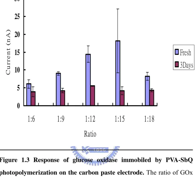
(36) oxidase may leak out of the polypyrrole matrix during successive reactions, meanwhile free radicals produced during the process of polymerization may attack the glucose oxidase and result in inactivation.. Photopolymerization One of mild gel entrapments is based on the photo-crosslinking of polyvinyl alcohol substituted with light-sensitive styrylpyridinium groups (PVA-SbQ). PVA-SbQ, photopolymer, was used in this work due to its excellent mechanical property and providing a direct coating process without other redundant steps. The entrapment of bimolecular may influence its structure as a well-organized network structure. Hence, an optimal ratio of bimolecular and PVA-SbQ should be carefully evaluated. Thus, we prepared different ratio of glucose oxidase to PVA-SbQ in the entrapment process in order to obtain an optimal protocol for the preparation of PVA-SbQ entrapped glucose oxidase electrode. Although, the best response was obtained when the ratio of GOx to PVA-SbQ was 1:15 ratio, the reproducibility was low. The Gox to PVA-SbQ was finally set at 1:12 due to (Ⅰ) the process was reproducible (Ⅱ) the entrapped enzyme can be stored for a longer time and (Ⅲ) a good response can be obtained (Fig 1.3). Notably, the response was much more sensitive than the enzyme electrode fabricated by polypyrrole polymerization.. Electrode Modification by Polypyrrole Although polypyrrole may not be suitable for the fabrication of the biosensor, a higher response was obtained from the oxidative response of 36.
(37) hydrogen peroxide on the Ppy-modified electrode. It suggested that the electro-signal could be amplified by the polypyrrole. Generally, the eletropolymerization of pyrrole was performed using cyclic voltammetry between 0.0 V and 1.0 V. Theoretically, the current represents the amount of polypyrrole deposited on the electrode, as indicated why the increasing on the cyclic voltammetry of Ppy/GOx electrodes produced by electropolymerization at different potential. The responses of electrodes were 1277 nA, 474 nA and 219 nA for 0-1 V, 0-1.5 V and 0-2 V, respectively (Fig 1.4). The responses become lower when the electropolymerization of pyrrole was profound under wider potential range. This is probably overoxidization of polypyrrole at high potential. The overoxidation of polypyrrole may incorporate hydroxyl groups at the 4’ position or carbonyl groups at the 3’ position on the polypyrrole chain (Beck et al., 1987). A conformational change may occur and cause the attenuation of the conductivity of polypyrrole. The overoxidation can bring a lot of positive charge on the pyrrole ring so that more time was needed to yield a stable background current (Fig 1.4).. Electropolymerization under Different Ionic Strengths The initial step of pyrrole electropolymerization is to induce the formation of free radicals, which repetitively couples to touch other and form network like structure. Hence, the presence of electrolyte can promote the release of the electron from pyrrole monomer and make the polymerization easier. The character of the ionic species was important for the property of polypyrrole, such as film morphology, conductivity and mechanical behaviors (David et al., 1995; Mikhail et al., 1997). 37.
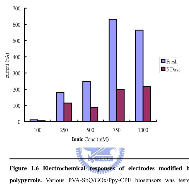
(38) Chloride ion has high electron negativity, an ability for an atom in a molecule to attract shared electrons to itself that can bring out more free radicals on the pyrrole monomer. When polypyrrole takes the chloride molecule as the dopant, its conducting ability could be greatly enhanced (Heeger et al., 1986). Thus, different concentrations of potassium chloride were used as the electrolytes in the electropolymerization of pyrrole. As expected, electropolymerization of pyrrole was more efficient, if the ionic strength was higher as indicated by the higher oxidative current, a representative. of. the. pyrrole. polymerization,. of. the. resulting. polypyrrole-modified CPE (Fig. 1.5). The maximum enhancing effect of KCl was seen at 750 mM. Oxidative potential of hydrogen peroxide was not changed by polypyrroles generated under different conditions. The GOX was then immobilized on the polypyrrole-modified carbon paste electrode (CPE) by PVA-SbQ with a ratio of GOX:PVA-SbQ fixed at 1:12. The fabricated glucose sensors were used for subsequent electrochemical analyses. The result shows that polypyrrole generated in the high ionic strength (>750 mM KCl) could not only improve its conducting property (Fig. 1.5), but also enhance the oxidative response to the hydrogen peroxide (Fig. 1.6). The. glucose. biosensors. fabricated. on. the. plan. CPE. or. polypyrrole-modified CPE are not quite stable. The reactivity of these types of biosensors to glucose decreased rapidly within 3~5 days (Figs. 1.3 and 1.6). Polypyrrole may not be the proper microenvironment for the glucose oxidase. Alternatively, polypyrrole-modified electrode may lose its intrinsic electroactivity after being oxidized by oxygen or hydrogen peroxidase under the atmosphere (Takeoka et al., 1998). 38.
(39) SEM of the Electrode Surface The morphology of polypyrrole-modified electrode was monitored under the scanning electronic microscope (SEM). We hope that the result can help us to find out why this electrode has the superior response than bare carbon paste electrode. The result from SEM shows that the bare carbon paste electrode showed a lot of colloidal materials and carbon slices (Fig 1.7A). After modified with polypyrrole, a thick, smooth polypyrrole layer covered the surface of electrode could be seen (Fig 1.7B). The surface area of carbon-paste electrode can be enlarged by these polymers and hence increase the conductivity of modified electrode. It is consistent with the previous observation (Heeger et al., 1980 and references therein) that ionic concentration would increase the porosity of the polypyrrole on the electrode so that surface area could increase (Fig 1.8).. Reusability of the Polypyrrole-Modified Electrode The glucose biosensor fabricated on the polypyrrole-modified electrodes was used as the working electrode to perform their reusability. As shown in Fig. 1.9, the response of the constructed glucose biosensor attenuated gradually along with the numbers of operation. It has been suggested that polypyrrole could be damaged by the oxidation of hydrogen peroxide as well as oxygen species. Hence, it is possible that the backbone of the polypyrrole was deteriorated by the hydrogen peroxide produced from the reaction of glucose oxidase leading to the reduction of the conductivity and the oxidative responses of pyrrole polymers (Belanger et al., 1989). The adhered polypyrrole might ware off the surface of electrode, so that the surface area of polypyrrole and the 39.
(40) conductivity of the polypyrrole-modified electrode was reduced compared with the untreated one (Fig. 1.10). In conclusion, we have fabricated a glucose biosensor using a polypyrrole-modified CPE. Several properties of this electrode, such as the morphology, conducting ability and sensitivity for the substrate, were studied. It is demonstrated that electropolymerization of pyrrole can be enhanced by high ionic strength. The modification of carbon-paste electrode by polypyrrole can increase the surface area and hence the conductivity of the electrode. Notably, the integrity of the architecture of polypyrrole may be deteriorated by the oxygen and hydrogen peroxide. Generally, oxidase enzymes incorporate oxygen to take place oxidative reaction and then subsequent product was H2O2. Using the pyrrole derivatives to improve its application in the fabrication of biosensors may solve this problem. Alternatively, mediators can be used to replace oxygen. Mediators can react with oxidases so that subsequent product of the oxidases would be the reductive mediator instead of H2O2. The advantage of using mediators is to avoid the deterioration of the polypyrrole layer. Another interesting strategy is using dehydrogenases instead of oxidases for the fabrication of biosensors. Dehydrogenases can carry out the reoxidative reaction without the formation of H2O2.. 40.
(41) Part II Palladium (Pd), a silver-white transition metal, is commonly used in the fabrication of electrochemical type electrode due to its ability to catalyze the oxidation of H2O2. In this work we fabricated glucose biosensors by immobilizing glucose oxidase on the Pd electrodes. Various thicknesses of Pd thin films (50, 100, and 150 nm) were deposited on the carbon-paste electrode (CPE) by sputtering and were designated as PdS50-CPE, PdS100-CPE and PdS150-CPE, respectively.. Characterization of Pd-modified Carbon Paste Electrode The redox potential of PdS-CPE was first characterized by cyclic voltammetry (CV). In order to avoid over-oxidation at high anodic applied voltages, the potential employed in this experiment in the pH 7.0 phosphorus buffer was set below 800 mV. The CV analysis was carried out with a scanning range between –0.8 and 0.8 V for PdS-CPEs and bare CPE (Fig 2.1). The cyclic voltammogram of PdS50-CPEs was similar to that of bare CPE, suggesting that the Pd layer on the CPE did not have an integral property (Chang et al., 2003). During sputtering, Pd layer deposited on the solid substrate changes gradually from many isolated Pd islands to a discontinuous thin film and finally into a continuous thin film. It is well established that the resistivity of metallic films increases with reducing thickness (Kawamura et al., 2000). As shown in Fig. 1.7, the surface of CPE is rough and consists of a lot of cavities. Hence, deposition of 50 nm thick Pd thin films might not be enough to cover all the surface of the CPE and produce the discontinuous films like isolated islands on the electrode. 41.
(42) The cyclic voltammograms of PdS100-CPE and PdS150-CPE exhibit distinct patterns, which were similar to that of Pt electrode having pronounced cathodic arms associated with the reduction of oxides on the surface (Hall et al., 1998). It has been shown that an oxidative current of palladium (0) to palladium (II) could be observed with potential above 450 mV (Lubert et al., 2001). PdS150-CPE showed lower current density than PdS100-CPE may be owing to its smaller surface area (Fig. 2.1). Most of the cavities on the carbon paste electrode may be filled by the Pd layer of 150 nm thick and results in a smooth surface and small surface area. Roughness of the electrode surface can provide more active area for the interaction of substrates than the one with smooth surface. Among three PdS-CPEs, PdS100-CPE exhibits a highest conductivity and catalytic ability to H2O2. As a result, PdS100-CPE was used for the fabrication of glucose biosensor.. Catalytic Property of Palladium for Hydrogen Peroxide Hydrogen peroxide can be oxidized on the carbon paste electrode with a potential above 700 mV (Fig. 2.2). This result is consistent with the normal oxidative potential that catalyzes the conversion of hydrogen peroxide to O2 on a electrode without any catalyzing activity. Under such a high oxidative potential, however, several interference may be observed from the oxidative responses of ascorbic acid, urea and acetaminophen in the serum. Several strategies were used to solve this problem, such as using mediators to decrease working potential or covering by a selective membrane to hinder the interfering substances outside the reaction area (Karyakin et al., 1999; Vaidya et al., 1995). The usage of catalytic 42.
(43) metallic film, such as Pd and Pt, as the electrode is another way to reduce the working potential. As mentioned in Section IV-2-1, the anodic potential was applied to facilitate reaction (4) (Section IV-2-1) to take place rapidly so as to produce oxidative current. Our studies suggest that a potential as low as 200 mV is sufficient to trigger the electron transfer from H2O2 to the electrode. The oxidative current markedly increased at 200 mV, while that at 100 mV was about 10 times less. The phenomenon might result from the change of the composition of complex on the electrode, that is, Pd(OH)2·H2O2 increased drastically and the change of equilibrium constants, that is, K3 was larger than K2 (Hall et al., 1998). With sufficient anodic potential, Pd(0) would be oxidized to Pd(II) and subsequently turned to Pd(OH)2 with H2O. Pd(OH)2 could offer bonding site for H2O2 to allow subsequent reaction to occur. When K3 larger than K2, it means reaction (3) become rate-limiting step so that reaction (4) carried out as soon as reaction (3) took place. As the result, the oxidative current could raise drastically. Therefore, palladinized electrode allows a substantial decrease in applied working potential and amplified oxidative current from the oxidation of H2O2. In order to increase detecting sensitivity and lower interference noise, we chose the 500 mV as working potential. To accord with our data, all operating potential was set at 500 mV.. Fabrication and Characterization of PVA-SbQ/Gox/Pd Electrode Glucose oxidase was encapsulated on various PdS-CPEs using PVA-SbQ, PVA-SbQ/GOx/PdS50-CPE, PVA-SbQ/GOx/PdS100-CPE and PVA-SbQ/GOx/PdS150-CPE, as described previously. Fig. 2.2 shows the 43.
(44) responses of fabricated glucose biosensors in the presence of 1 mM glucose. The oxidative currents were 28 nA, 3100 nA and 234 nA for PVA-SbQ/GOx/PdS50-CPE,. PVA-SbQ/GOx/PdS100-CPE. PVA-SbQ/GOx/PdS150-CPE,. respectively.. As. and expected,. PVA-SbQ/GOx/PdS100-CPE showed the best response among three glucose biosensors. Notably, the balanced background current of the glucose biosensor decreased from the scale of 10-7 A to 10-9 A after several runs of performance (data not shown). Background current acts like the threshold. The response of biosensor must be at least equivalent or even superior to the background current or the signal would not be clear enough to be detected. In this aspect, Pd electrode was more suitable than polypyrrole electrode for the fabricating the biosensors.. Electrodeposition of Palladium on the Carbon-paste Electrode Besides the sputtering, we tried another method, electrodeposition by cyclic voltammetry, to modify the surface of the CPEs (Lubert et al., 2001; Chang et al., 2003). Fig. 2.4 indicates the Pd (II) started to reduce under the – 0.1 V and reductive potential was located at – 0.3 V. In a pH 7.0 solution, chloropalladate can be adsorbed on the carbon paste electrode surface in a slow reaction during potentiostatic treatment. It means that chloropalladate species could also be accumulated on the electrode surface during cyclic voltammetry. Therefore, the increase of the peak current at – 0.3 V could be attributed to the accumulation of the Pd (0) deposition during cycling. Three Pd-electrodeposited CPEs, Pde10-CPE, Pde15-CPE, and Pde20-CPE, were generated by cyclic scanning in the presence of 5 mM palladium chloride at pH 7.0 between -0.4 V and 44.
(45) 1.0 V for 10, 15, and 20 cycles, respectively. Subsequently, glucose oxidase was immobilized on the palladinized CPE. using. PVA-SbQ,. termed. PVA-SbQ/GOx/Pde10-CPE,. PVA-SbQ/GOx/Pde15-CPE and PVA-SbQ/GOx/Pde20-CPE as described previously. The sensing responses of these glucose biosensors were characterized by subjecting to electrochemical analysis. The result showed that the sensing sensitivity of all three PVA-SbQ/GOx/Pde-CPEs was hundreds times higher than that of glucose biosensor fabricated on the. unmodified. CPE. (Fig.. 2.5).. Notable,. all. three. PVA-SbQ/GOx/Pde-CPEs exhibit a similar sensing response to that of PVA-SbQ/GOx/PdS100-CPE, although PVA-SbQ/GOx/Pde15-CPE is the best one among three similar types of glucose biosensors. It is postulated that the thickness of Pd during electrodeposition was affected by the scanning cycles. Although modify CPE by electrodeposition is easy, quick and less expensive, this method is suffered from the inconsistency due to the unknown reason. We could not obtain the consistent response for each preparation of Pd-electrodeposited CPE. It seems that several experiment parameters, including potentiostatic treatment, the type of palladate and electrolyte, need to be improved in the future studies (Lubert et al., 2001). Consequently, we still took advantage of sputtering technology to perform subsequent experiments.. Sensing Dynamic Range of PVA-SbQ/GOx/PdS100-CPE biosensor Fig.. 2.6. showed. the. current-time. response. curve. of. PVA-SbQ/GOx/PdS100-CPE biosensor by step-wise adding 10 µM glucose. A fast, sensitive and uniform response to each addition was observed in 45.
(46) an additive manner was observed (Fig. 2.6). The result suggests that PVA-SbQ/GOx/PdS100-CPE biosensor can be used for a continuous performance in the medical application. Furthermore, this result also demonstrated that PVA-SbQ could allow glucose to pass through and reach glucose oxidase. The electron transfer to the electrode was also not obstructed. by. this. photosensitive. emulsion.. The. PVA-SbQ/GOx/PdS100-CPE biosensor exhibits a linear dynamic range for glucose from 0.5 µM to 1000 µM, with a slope of 4.8 nA/µM glucose and a correlation coefficient of 0.997 (Fig. 2.7). The detection limit of PVA-SbQ/GOx/PdS100-CPE biosensor for glucose can be as low as 0.5 μ M.. Reproducibility and Stability of PVA-SbQ/GOx/PdS100-CPE biosensor The. availability. of. PVA-SbQ/GOx/PdS100-CPE. biosensor. for. repeating measurements were performed using 10μM and 1 mM glucose as working conditions. The PVA-SbQ/GOx/PdS100-CPE biosensor exhibited a stable response to 10 µM or 1 mM glucose even after 10-20 consecutive reactions. The relative standard derivation for reproducibility of PVA-SbQ/GOx/PdS100-CPE biosensor in response to 10 µM and 1 mM glucoses were 4.21 % and 8.62 %, respectively. This result demonstrates that the fabricated glucose biosensor can be repeatedly used at least 10-20 times without losing the encapsulated enzyme as well as the integrity of the Pd-modified electrode and the PVA-SbQ membrane. This observation indicates that PVA-SbQ/GOx/PdS100-CPE biosensor has a good operational stability for multiple-use or continuous analysis. Furthermore, 46.
(47) this result revealed that PVA-SbQ/GOx/PdS100-CPE biosensor was quite reliable when detecting low concentration of substrate, but with moderate reliability when detecting high concentration of substrate. According to Fick’s law, the redox current (at any time) is proportional to the concentration gradient of the electroactive species from bulk solution to the electrode. The reaction chamber used in this study is relative large (10 mL). With the addition of high concentration of substrate into the reaction solution with stir, the concentration gradient between bulk and reaction layer becomes complicated. So, the unreliable result could occur when detecting high concentration of substrates. This problem can be improved by designing a small volume chamber, such as microfabrication, or using continuous reaction system, such as FIA. The storage stability of PVA-SbQ/GOx/PdS100-CPE biosensor was also investigated. The PVA-SbQ/GOx/PdS100-CPE biosensor was stored at 4 ℃ in the intervals between the consecutive reactions. The activity assay of PVA-SbQ/GOx/PdS100-CPE biosensor in the presence of 100 µM glucose after long-term storage was shown in Fig. 2.9. The response of the PVA-SbQ/GOx/PdS100-CPE biosensor to glucose increased gradually during the initial days and elevated abruptly after 21 days storage. This may be due to the swelling of PVA-SbQ membrane during storage and reached to the optimal structure after 21 days (Fig. 2.9). Similar result was also observed elsewhere (Chang et al. 2003). The response of fabricated glucose biosensor remained stable for at least 3 months. After 88 days of storage, the R.S.D of the response began to increase, although the biosensor was rather active. It is suggested that PVA-SbQ membrane 47.
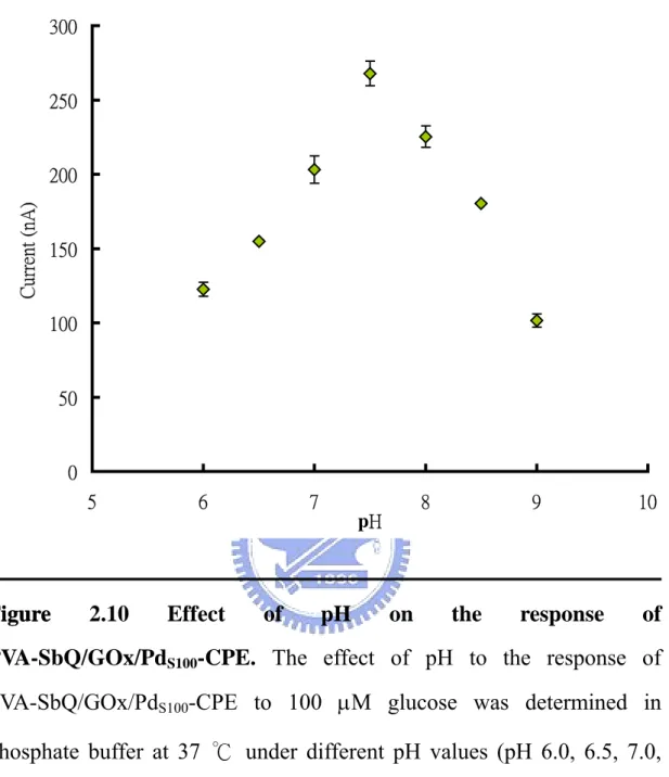
(48) is going to be fractured leading to the increase of the noise. The effect of pH on the response of PVA-SbQ/GOx/PdS100-CPE biosensor (Fig. 2.10) was examined in the pH range from 6 to 9. The maximum activity was observed at pH 7.5. The activity decreased rapidly below or above pH 7.5. In conclusion, we have generated two types of glucose sensors fabricated on the Pd-modified CPEs by sputtering and electrodeposition technology. Palladium exhibits an excellent catalytic ability to oxidize H2O2 and hence used widely in the oxidases-based biosensor design. Pd deposition on the CPE can be carried out by electrodeposition using cyclic voltammetry (Chang et al., 2003). However, modification of CPE by Pd through sputtering has not been established. In this work, we for the first time showed that CPE could be modified by the Pd thin film through sputtering. Our studies showed that glucose biosensor fabricated on Pd-modified CPE exhibited an excellent stability, reproducibility and sensitivity to the substrate. Pd-modified electrodes can be used to develop various oxidase-based amperometric biosensors. The enzyme can be immobilized using photo-sensitive polymer PVA-SbQ. The application of photopolymer system for enzyme encapsulation and immobilization was demonstrated to be suitable for automated production techniques and miniaturization of sensors using photolithography. The detection limit of the PVA-SbQ/GOx/PdS100-CPE biosensor was 0.5 µM glucose. A linear relationship was found between 0.5 µM to 1000 µM and its R square value was 0.977.. 48.
(49) Part III Immobilization of enzymes on the electrode by direct cross-linking is still the popular way in the design a biosensor. However, except Au, direct cross-linking is impossible to occur between enzyme and any other metallic material. To solve this problem the plasma-enhanced chemical vapor deposition (PECVD) technique was performed. Direct Cross-Link of Enzyme on the NH2-modifeid Pd Electrode The NH2-modified Pd-CPE, (NH2)Pd-CPE, was use for the direct cross-linking of glucose oxidase on the surface. The CPE electrode without NH2-plasma treatment was used in this experiment as the control. The cross-linking was performed by immersing both electrodes with 1mg/mL GOx in the presence of 2% glutaraldehyde under the room temperature for overnight. Both electrodes (GOx-X-Pd-CPE and unmodified CPE) were then subjected to electrochemical analysis in response to glucose. The oxidative current of the control electrode was detectable, but consisted of a lot of noises and decreased gradually during the reaction (Fig. 3.1). Glucose oxidase might immobilize on the electrode by a physical adsorption, so that the adherent strength was not strong enough to produce a stable response and to be easy peeled off. The electrode modified by NH2-plasma showed significant response and stable current to glucose. It appeared that glucose oxidase immobile by covalent bounding on the electrode surface firmly. The above result was further confirmed by generating NH2-modified Pd-CPE using different powers (50 W, 100 W and 150 W), termed X50-Pd-CPE, X100-Pd-CPE and X150-Pd-CPE. As shown in Fig. 3.2, the greater power used, the greater response could be obtained. The number 49.
(50) of amino groups could be excited and linked on the surface of the Pd electrode seemed to be mediated by the power applied during the PECVD. The number of amino groups on the electrode is proportional to the number of reactive sites for the covalent bonding of enzymes on the electrode. Although PECVD under the power of 150 W exhibited the highest response to 10 mM glucose among condition used. More experiments are needed to find out the optimal parameters to perform the PECVD.. Successive Operation The GOx-X150-Pd-CPE was selected to perform subsequent electrochemical experiments in the presence of 500 µM glucose. Without the hindrance of PVA-SbQ membrane, the diffusion of glucose from bulk solution to the active site of enzyme was faster than that of the PVA-SbQ/GOx/PdS100-CPE biosensor in just a few seconds (~5 sec). The plasma films were so thin that the distance between the electrode and the reaction center of enzyme was very close. As a result, a short steady-state response was obtained (~15 sec). During the crosslinking process, glutaraldehyde cross-link with each other and glucose oxidase leading to the formation of the intra- and intermolecular networks. The resulting 3D conformation, which affected the enzyme kinetic and diffusion characteristics, was complex. Hence, the pathways of glucose entering the active site and electron transferring to the electrode were complicate, resulting in the noisier and uneven baseline.. Performance for Being a Biosensor 50.
(51) Fig. 3.4 depicted the detection limit and linear dynamic range of GOx-X150-Pd-CPE biosensor at 25 ℃ . The result showed that GOx-X150-Pd-CPE biosensor could detect as low as 10 µM glucose with an oxidative current of 11.65 nA. This biosensor exhibited a good linearity for sensing the glucose from 10 µM to 1 mM with a sensitivity of 0.67 nA/µM. The reusability of GOx-X150-Pd-CPE biosensor was studied in the presence of 50 µM glucose and 500 µM glucose. The result showed that GOx-X150-Pd-CPE biosensor could be repeatedly used at least 15 times (50 µM glucose) and 10 times (500 µM glucose) without losing its activity. The relative standard derivation of the GOx-X150-Pd-CPE biosensor in response to 50 µM glucose and 500 µM glucose were 4.42 % and 7.6 %, respectively. It revealed the GOx-X150-Pd-CPE biosensor was reliable when detecting low concentration of glucose. This result is consistent with the result found in PVA-SbQ/GOx/PdS100-CPE biosensor. The storage ability of GOx-X150-Pd-CPE biosensor was also investigated. Three sets of GOx-X150-Pd-CPE biosensor fabricated with different power were storage at 4 ℃. in the intervals between. consecutive reactions during the experiment. The responses of all three types of biosensors lost along with the storage time. One possible explanation is that without the protection of PVA-SbQ matrix glucose oxidase may denature gradually during the storage. This problem can be solved by covering the covalent-bound GOx with the PVA-SbQ or other organic and inorganic matrices. Another explanation for this phenomenon could be due to the weak linkage between the amino group and Pd 51.
(52) electrode. These unstable groups peel off from the electrode surface along with the glucose oxidase after several days. In conclusion, we combined the plasma-enhanced chemical modification. technology. and. crosslink. immobilization. with. glutaraldehyde leading to a novel way for the design and fabrication of biosensors. Miniatured biosensors are typically fabricated using micromachining techniques and semiconductor process, such as deposition, patterning, doping and etching (as shown in Appendix 13), which are identical with those used in IC fabrication (Hierlemann et al., 2003). Key advantages of miniatured biosensor include small sample volume needed, retaining high concentration of the original sample, quick response, precise geometric control in the fabrication steps, mass production and low cost. However, there is one problem with respect to how well the biological components (i.e. wet process) are combined to the surface of the transducers (i.e. dry process). Thus, the conventional technique for interfacial design, such as silane coupling, Nafion film encapsulation, electropolymerized conducting polymer film, and self-assembling monolayers, are unsuitable for mass production of miniatured biosensor because of the involvement of so called ‘‘ wet process’’. In our study, the performance of glucose biosensors gave a rapid, reproducible and pretty good sensitive response. The improvement of this glucose biosensor could be investigated more in order to advance performance for medical, clinical, food industry application and so on. Most importantly the plasma-enhanced chemical modification and sputtering technologies open a new field for miniaturization and mass 52.
(53) production of biosensors using bio-microelectromechanical systems (BioMEMS).. 53.
數據

Outline
相關文件
版面為 A4 單面全彩印刷。桂冠葉及星星圖案以燙金方式印刷。... 附件四
The debate between Neo-Confucianists and Buddhists during the Song-Ming dynasties, in particular, the Buddhist counter-argument in retaliation of Neo-Confucianist criticism, is
A factorization method for reconstructing an impenetrable obstacle in a homogeneous medium (Helmholtz equation) using the spectral data of the far-field operator was developed
A factorization method for reconstructing an impenetrable obstacle in a homogeneous medium (Helmholtz equation) using the spectral data of the far- eld operator was developed
In Case 1, we first deflate the zero eigenvalues to infinity and then apply the JD method to the deflated system to locate a small group of positive eigenvalues (15-20
reference electrode:參考電極 indicator
The quantity of landscape planting in campus was evaluated and used as an indicator to divide the campus into different landscape zones where the air anions
Iwai , “A self-aligned emitter base NiSi electrode technology for advanced high-speed bipolar LSIs” , in IEEE Bipolar/BiCMOS Circuits and Technology Meeting , pp..
