國
立
交
通
大
學
電子物理系所
博
士
論
文
多鐵性正交結構鈥錳氧薄膜之磁電特性研究
Magnetoelectric characteristics of substrate-stabilized
multiferroic orthorhombic HoMnO
3thin films
研 究 生:林宗漢
指導教授:莊振益 教授
多鐵性正交結構鈥錳氧薄膜之磁電特性研究
Magnetoelectric characteristics of substrate-stabilized
multiferroic orthorhombic HoMnO
3thin films
研 究 生:林宗漢 Student:Tjung-Han Lin
指導教授:莊振益教授 Advisor:Prof. Jenh-Yih Juang
國 立 交 通 大 學
電 子 物 理 系 所
博 士 論 文
A Dissertation
Submitted to Department of Electrophysics College of Science
National Chiao Tung University in Partial Fulfillment of the Requirements
for the Degree of Doctor of Philosophy
in Electrophysics
July 2010
多鐵性正交結構鈥錳氧薄膜之磁電特性研究
研究生: 林宗漢
指導教授: 莊振益 教授
國立交通大學
電子物理系所
中文摘要
本論文主要研究具有 E-type 反鐵磁有序磁結構之多鐵性正交結構
鈥錳氧薄膜之磁有序誘發鐵電特性等物理性質。我們首先以固態燒結
法製備出具有六方結構的稀土元素錳氧化物(離子半徑較小之鈥元
素)
;並利用 X-ray 繞射儀及超導量子干涉儀(SQUID)來分析靶材之晶
體結構與磁相變等特性。另一方面,為了探索其正交結構磁電耦合之
基本物理特性,本研究乃以製備具良好晶軸取向之薄膜為初期之首要
目標。實驗結果顯示藉由選擇鈦酸鍶(110)、鑭鋁氧(110)、與鈦酸鍶(100)
三種基板,我們可分別製備出具單一軸向之 a、b、與 c 軸薄膜;除此
之外,亦藉由上述匹配之基板來調變鈥錳氧薄膜正交結構之晶格常
數,進而利用這些薄膜來進行相關磁電特性的量測以確認磁電耦合的
機制是否存在,並與理論預測做比較。
Magnetoelectric characteristics of substrate-stabilized
multiferroic orthorhombic HoMnO
3thin films
Student: Tjung-Han Lin
Advisor: Prof. Jenh-Yih Juang
Department of Electrophysics
National Chiao Tung University
Abstract
This dissertation is aimed primarily at exploring the manifestations of magnetic
ordering induced ferroelectricity expected in the E-type multiferroic orthorhombic
HoMnO3. We first prepare the hexagonal HoMnO3 bulk synthesized by conventional solid-state reaction processes. The structural and magnetic characteristics of these
samples were examined by x-ray diffraction and superconducting quantum interference
device (SQUID) to ensure the stoichiometry of the material. Since within the
frameworks of various microscopic mechanisms the magnetic ordering and associated
ferroelectricity are intimately related to specific crystallographic orientations, it is thus
essential to obtain well-aligned orthorhombic HoMnO3 (o-HMO) thin films capable of revealing the relevant properties along respective crystallographic orientations. To this
and c-axis-oriented o-HMO thin films. Moreover, the external strain force originated
from the epitaxial relation between these substrates and thin films during deposition can
also serve as an excellent method in slightly modifying the lattice parameters with
desired crystal structures. Finally, the magnetic ordering anisotropy and the
ferroelectricity in these epitaxial o-HMO thin films were investigated to check whether
or not the predicted marked enhancement of the magnetoelectric effect does indeed
Contents
Abstract (in Chinese) i
Abstract (in English) ii
Contents iv
List of Figures vi
Chapter 1 Introduction 1
1.1 The discovery of manganites with gigantic magnetoelectric effect 1 1.2 Origin of the magnetism-induced ferroelectricity in multiferroic
orthorhombic RMnO3
6
1.2.1 Spiral magnetism 6
1.2.2 Collinear magnetism 9
1.3 Survey of the magnetic phase diagram versus R3+-ion radius in the perovskites RMnO3 family
11
1.4 Motivation 13
1.5 Organization of this dissertation 15
References 16
Chapter 2 Exchange interactions and environmental effects in perovskite manganites
18
2.1 Introduction 18
2.2 Superexchange 18
2.3 Double exchange 19
2.4 Crystal field and Jahn-Teller effect 21
2.5 Tolerance Factor and E-phase magnetic structure 23
References 26
Chapter 3 Experimental procedures 27
3.1 Preparation and characterization of polycrystalline sample of hexagonal HoMnO3
27
3.1.1 Introduction 27
3.1.2 Experimental 28
3.1.3 Results and discussion 28
3.2 Epitaxial stabilization of oxide thin films 32
3.2.1 The b-axis-oriented o-HoMnO3 thin films 35
3.2.2 The c-axis-oriented o-HoMnO3 thin films 36 3.2.1 The a-axis-oriented o-HoMnO3 thin films 36
References 38
Chapter 4 Magnetoelectric properties of orthorhombic HoMnO3 thin
films with various orientations
40
4.1 Anomalous magnetic ordering in b-axis-oriented HoMnO3 thin films
40
4.1.1 Probing the anisotropic characterization of orthorhombic HoMnO3 thin films
40
4.1.2 Results and Discussion 41
4.2 Strain-induced effects on antiferromagnetic ordering and magnetocapacitance in orthorhombic HoMnO3 thin films
46
4.2.1 Directly probing the magnetoelectric coupling in orthorhombic HoMnO3 thin films
46
4.2.2 Results and Discussion 48
4.2.3 Summary 54
4.3 Magnetism-induced ferroelectric polarization in the
c-axis-oriented orthorhombic HoMnO3 thin films
55
4.3.1 Introduction 55
4.3.2 Results and Discussion 57
4.3.3 Summary 63
4.4 Magnetic and electric properties of the a-axis-oriented orthorhombic HoMnO3 thin films
64
4.4.1 Introduction 64
4.4.2 Results and Discussion 65
4.4.3 Summary 72
References 73
Chapter 5 Summary and conclusions 76
Biographical notes 78
List of Figures
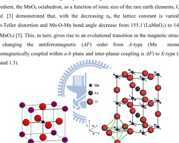
Fig. 1.1 Schematic crystal structure of cubic perovskite ABO3 (Left) and
BO6 octahedron (Right) in a perovskite structure.
2
Fig. 1.2 Magnetic phase diagram for RMnO3 as a function of the ionic radius of R (rR).
3
Fig. 1.3 Crystal structures of LaMnO3 and HoMnO3. Spin (arrows) and orbital (lobes) ordered features are also illustrated. The stack of spin and orbital order along the c axis is staggered and uniform order, respectively, for both the compounds.
3
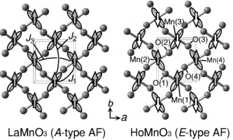
Fig. 1.4 (a) In-plane arrangement of Mn and O atoms. Arrows denote the direction of spins and AFM-coupled zigzag spin chains are highlighted by shaded areas. (b) Arrows show the directions of the ionic displacements for Mn (left) and O (right) in AFM-E. The thick arrows at the bottom show the direction of the resulting displacements of Mn and O sublattices and P.
5
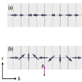
Fig. 1.5 Ordering of Mn-spins in multiferroic TbMnO3 in (a) the high temperature SDW phase below TN = 41 K and (b) in the ferroelectric cycloidal phase below TL = 28 K.
6
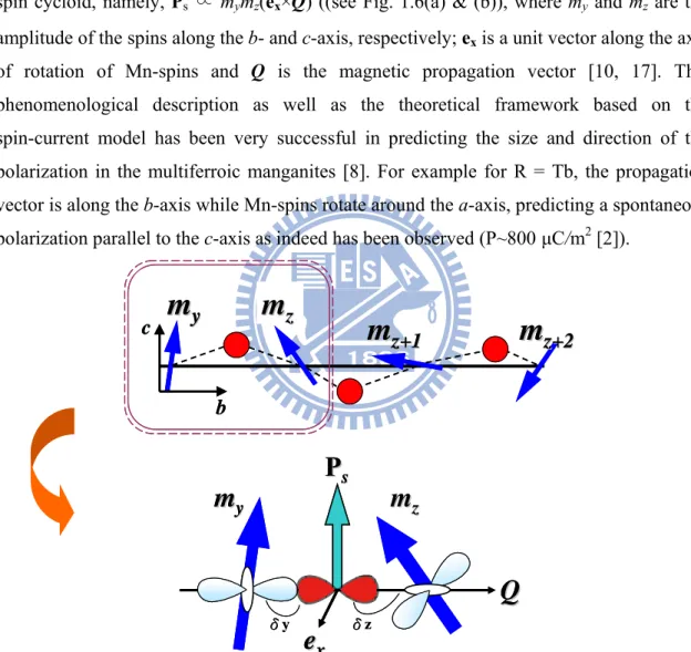
Fig. 1.6 (a) The bc-plane of the spin structure and positions occupied by the O ions (red circles). (b) The relations of the TM-O-TM cluster model (TM: transition-metal) with the rod-type d3x2-r2/ d3y2-r2 staggered orbital order under a noncollinear spin configuration (my
and mz are the magnetic spins) with the associated electric
polarization Ps. δy and δz denote the pd-hybridization.
7
Fig. 1.7 (a) Magnetic unit cells of the E-phase domain in HoMnO3.The arrows on the Mn atoms denote the directions of their spins. The FE displacements are not shown, but the direction of P is indicated [12]. (b) Atomic displacements in FE HoMnO3, as obtained by the difference of atomic coordinates in optimized AFM-E spin configuration (length of arrows in arbitrary units). In the ab-plane, the AFM-E spin arrangement is also shown with black (right) and white (left) Mn atoms. (c)AFM-coupled zigzag spin chains are highlighted by shaded areas. The black-rimmed arrow at the right shows the direction of the resulting displacements of O sublattices [11]. (d) Thin blue vertical arrows denote the direction of Mn spins in the ‘straight’ Mn chains of the magnetic E-type ordering, cf. Fig. 1.7(b). Double exchange drives the Mn–O–Mn angle away from 180◦ when spins are antiparallel and towards it when spins are parallel. Orange vertical arrows indicate the resulting oxygen displacements; the direction of the ferroelectric polarization is indicated on the right of the chain by the red arrow. This picture applied to the E-type manganites gives a net electrical polarization indicated in the panel of Fig 1.7(b).
10
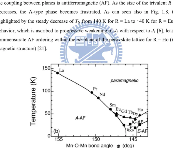
Fig. 1.8 Orbital ordering temperatures of RMnO3 as a Function of the in-plane Mn-O-Mn bond angle.
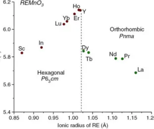
Fig. 1.9 Evolution of the lattice structure in RMnO3 as a function of the size of the rare earth (RE).
13
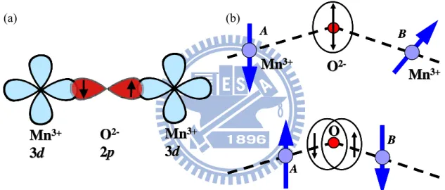
Fig. 2.1 (a) The overlap between the wave functions of O2- 2p and Mn3+ 3d states for the superexchange interaction. (b) When two Mn3+ ions are being brought up to an O2- ion from a large distance, the spin moments of two Mn3+ions are random relation and of oxygen ion is zero for net moment, due to the filled shells. When a manganese ion with an up(↑) spin is bound on the oxygen ion, the parallel spin of oxygen repels one another and forces another manganese to have a down(↓) spin.
19
Fig. 2.2 (a) and (b) The schemes of the double exchange mechanism which involves the conduction-electrons-hopping process. From [4, 8]. (c) The effective hoping (teff) of an eg electron jumping between two nearest-neighbor Mn ions (reproduced from Ref. [8]). (d) Sketch of a spin-canted state, as discussed by de Gennes.
21
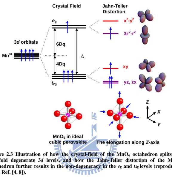
Fig. 2.3 Illustration of how the crystal-field of the MnO6 octahedron splits the five-fold degenerate 3d levels, and how the Jahn-Teller distortion of the MnO6 octahedron further results in the non-degeneracy in the eg and t2g levels.
23
Fig. 2.4 (a) The Pbnm orthorhombic cell of RMnO3. Black, white, and gray spheres represent O, Mn, and Ho atoms, respectively. From [12]. (b) ab in-plane view of MnO2 planes, showing the large octahedral distortions and zigzag spin ordering. Solid lines mark the in-plane projected unit cell. (c) The simple sine-wave magnetic structure of HoMnO3 for TL <T <TN (d) The E-phase
magnetic structure below TL.
25
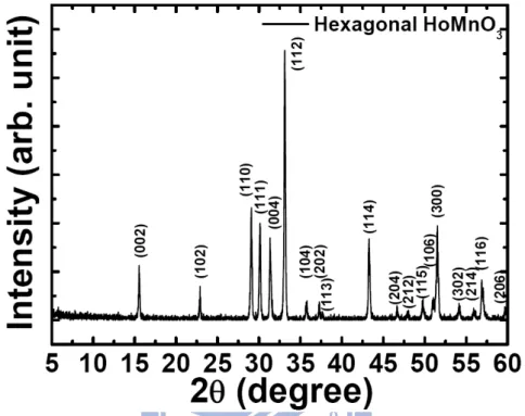
Fig. 3.1 The x-ray diffraction patterns of hexagonal HoMnO3 powder at room temperature.
29
Fig. 3.2 (a) Temperature evolution of the zero-field-cooled susceptibility (ZFC-χ(T)) with an applied magnetic field of 100 Oe. The inset shows the temperature-dependent inverse magnetic susceptibility. The lines indicate the Curie Weiss high-temperature extrapolation. (b) The ZFC and FC curves of χ(T) near the spin reorientation transition of Mn3+. The inset shows the ZFC and FC curves of χ(T) around AF ordering of Ho3+ magnetic moments.
31
Fig. 3.3 Schematics of a typical PLD process: a ceramic target is placed in a vacuum chamber and then a pulsed laser beam is focused onto the surface of the solid target. The strong absorption of the electromagnetic radiation by the solid surface leads to explosive evaporation of the target materials. The evaporated materials essentially form highly energetic and ionized plasma, often referred as “laser plume”.
Fig. 3.4 Illustration for describing the experimental processes carried out in this thesis.
35
Fig. 3.5 The schematics of the in-plane arrangements between the o-HMO thin films and substrates. (a) o-HMO (0k0)/LAO(110): c-axis and
a-axis of o-HMO are aligned with LAO[001] and LAO[110],
respectively; (b) o-HMO (00l)/STO(001): a-b diagonal of o-HMO is aligned randomly with STO [010] substrate direction, one expects that a twin-like structure might occur in these o-HMO (00l) films; and (c) in-plane schemes of o-HMO thin films on STO(110) showing that the c-axis of o-HMO is aligned with STO[001], but a-axis or b-axis can be randomly aligned with STO[110].
37
Fig. 4.1 (a) The typical θ-2θ diffraction pattern of o-HMO films grown on LAO(110) substrate. The inset in (a) shows the rocking curve of the o-HMO(020) peak. (b) The azimuthal φ-scans of the (110) peak of the o-HMO films, displaying the nearly ideal alignment of crystallographic orientations between film and substrate.
42
Fig. 4.2 The AFM image of a 180 nm-thick o-HMO film deposited on LAO(110) substrate. The arrows indicate the growth direction of
o-HMO grains.
43
Fig. 4.3 (a) The zero-field-cooled temperature-dependent magnetizations (ZFC-M(T)) for o-HMO film probed along different crystal orientations with an applied magnetic field of 100 Oe. (b) The ZFC-M(T) along the c-axis measured at 100 Oe and 500 Oe. The inset in (b) shows full temperature range of the FC- and ZFC-M(T) measured at 500 Oe. Notice the 30 K anomalous ordering along the c-axis and the significant suppression of it by applying merely 500 Oe.
45
Fig. 4.4 The XRD results of the o-HMO thin films grown on Nb:STO(001) substrates. (a) The
θ
-2θ
scans (intensity plotted in logarithmic scale) reveal that HMO films are indeed orthorhombic with nearly perfect c-axis oriented characteristic. The inset shows the rocking curve of the o-HMO (004) peak. (b) Theφ
-scan plot of the (202) peak of the o-HMO films indicates a clear fourfold symmetry, suggesting that the film is well-aligned along (001)-orientation, however, is of ab mixing character in film plane.49
Fig. 4.5 The temperature dependent magnetization (M(T)) of the o-HMO probed along the c-axis and the ab-plane. (a) The ZFC (solid symbols) and FC (open symbols) M(T)’s measured with a magnetic field of 100 Oe applying along the c-axis and in the
ab-plane. Both reveal an AFM transition temperature of 43.2 K.
(b) The enlarged version of the ZFC curves displayed in (a). A magnetic ordering near 34.6 K is evident in the c-axis.
50
indicates the presence of weak ferromagnetism. The inset shows the results in larger scale.
Fig. 4.7 The dielectric constant as a function of temperature measured along the c-axis of the o-HMO film. Significant suppression of the enhancement and peak temperature by the applied field are evident. The inset shows that the dielectric enhancement is non-hysteretic in temperature.
53
Fig. 4.8 The XRD diffraction patterns of the o-HMO thin films grown on STO(001) substrates. (a) The typical
θ
-2θ
scans (intensity plotted in logarithmic scale) reveal that HMO films are indeed orthorhombic with nearly perfect c-axis oriented characteristic. The inset in (a) shows the rocking curve of the o-HMO (004) peak. (b) The azimuthalφ
-scans (intensity plotted on a logarithmic scale) of the (202) peak of the o-HMO films, displaying the nearly ideal alignment of crystallographic orientations between film and substrate. The inset of (b) is a 2×2 μm2 AFM topographic image of a 180 nm-thick o-HMO film deposited on STO(001) substrate.58
Fig. 4.9 (a) The zero-field-cooled temperature-dependent magnetizations (ZFC-M(T)) for o-HMO film probed along the c-axis and the
ab-plane with an applied magnetic field of 100 Oe. Both reveal an AF transition temperature of 44.2 K. The inset in (a) shows the
FC- and ZFC-M(T) over the whole temperature range measured along the c-axis at 500 Oe. (b) The ZFC-M(T) along the c-axis measured at 100 Oe and 500 Oe. (For the sake of clarity the 500 Oe curve is slightly shifted.) The 0.2 K difference seen in TN for the 100 Oe and 500 Oe results is mainly due to different measuring temperature intervals used during measurements. As shown in the upper-right inset, when we change the temperature interval from 2 K to 1 K and re-measure part of the 100 Oe curve (indicated by the square frame), it evidently displays exactly the same TN as seen on the 500 Oe curve measured with the same temperature interval. The lower-left inset shows that the similar feature also occurs for o-HMO/Nb-STO film with a magnetic field of 500 Oe.
60
Fig. 4.10 P-E hysteresis loops of the o-HMO thin film grown on Nb-doped
SrTiO3(001) substrates measured at various temperatures. The inset shows the remnant polarization obtained by pulsed polarization measurement at various temperatures.
61
Fig. 4.11 (a) The XRD θ-2θ scan of the o-HMO thin film grown on Nb:STO(110) substrate, showing that the film is single-phase
a-axis-oriented orthorhombic perovskite manganites (in Pbnm
space group settings). The inset in (a) shows a rocking curve measured around the o-HMO (200) peak. (b) The φ-scans of the same film displayed in (a), showing the nearly perfect in-plane alignments between film and substrate.
67
Fig. 4.12 The zero-field-cooled (ZFC) χ(T) of the o-HMO films probed along the respective crystalline axis with an applied field of 100
Oe. The inset shows the temperature-dependence of first derivative of magnetization with respect to T measured with a 1000 Oe magnetic field along the c-axis.
Fig. 4.13 An enlarged vision of magnetic-field dependent magnetization (M-H) curves measured at 60, 35, 27, and 23.5 K. The inset shows a clear hysteretic behaviour displayed at 10 K indicating the presence of weak ferromagnetism.
69
Fig. 4.14 (a) The dielectric constant (εr)as a function of temperature for
o-HMO film evaluated from our measurements when cooling
(closed symbols) and warming (open symbols) the sample. The left inset shows the temperature-dependent inverse relative permittivity. The right inset shows the schematic cross-section view of the survey.
70
Fig. 4.15 The electric-field dependent polarization (P-E) hysteresis loops for the o-HMO/Nb:STO(110) measured at 40, and 13 K.
Chapter 1
Introduction
1.1 The discovery of manganites with gigantic
magnetoelectric effect
The mineral CaTiO3 found in the Ural Mountains, gave its name perovskite to a large
group of compounds which have been playing important roles in condensed matter physics and subjected to extensive investigations over the past several decades [1]. Among them, the perovskite manganites RMnO3 (R=rare earth) are of particular interests because of the
rich variety of intriguing emergent properties have been demonstrated to arising from the subtle interplays among the charge, spin, orbital, and lattice degree of freedoms. Colossal magnetoresistance (CMR) and charge ordering in hole-doped LaMnO3 have been the
subjects of great interest for the last decade, while recent discoveries of multiferroicity in TbMnO3 [2] and DyMnO3 [3] have created additional excitements in the studies of
manganites. These electronic behaviors are all strongly dependent on the underlying lattices, and detailed knowledge on how the properties and structure evolve with the size of the rare-earth ions is expected to provide significant insights into the complex physics of manganites.
In the crystal structure of cubic perovskite (ABO3), the A ion is residing at the eight
corners of the cube, as depicted by the violet spheres shown in left panel of Fig. 1.1. On the other hand, the B ion (shown as the dark-blue sphere) is sitting at the body-center and forms an octahedron with the six nearest neighbored oxygen ions residing at the center of the six faces (red circles). The right panel of Fig. 1.1 shows the ideal cubic perovskite structure of LaMnO3, and one can envisage it as being consisted of a cubic array of the corner-shared
BO6 octahedrons. However, the assumption of rigidity of perovskite structure is no longer
valid, if the central atom B is Jahn-Teller active, such as Cu2+ (3d9), Mn3+ (3d4), and Cr2+ (3d4). For these ions, the Jahn-Teller effect is equivalent to the orbital ordering of e
g states.
These states are doubly degenerated in a perfect octahedral coordination of the transition metal ions. Lifting this degeneracy by lowering the symmetry is the essence of the Jahn-Teller effect.
Perovskite RMnO3 compounds are insulators with the orthorhombic structure (space
group: Pbnm), where the distortion from the ideal cubic structure arises from two sources [5, 6]. One is the mismatch of R-O and Mn-O equilibrium bond lengths. In addition, the most significant effect on the crystal structure introduced by decreasing the ionic radius (rR)
is an enhancement of the cooperative rotation of the MnO6 octahedra characterized by the
decrease of Mn-O-Mn bond angle. By considering detailed structure of the most relevant ingredient, the MnO6 octahedron, as a function of ionic size of the rare earth elements, Goto
et al. [3] demonstrated that, with the decreasing rR, the lattice constant is varied by
Jahn-Teller distortion and Mn-O-Mn bond angle decrease from 155.1°(LaMnO3) to 140.4°
(LuMnO3) [5]. This, in turn, gives rise to an evolutional transition in the magnetic structure
by changing the antiferromagnetic (AF) order from A-type (Mn moments ferromagnetically coupled within a-b plane and inter-planar coupling is AF) to E-type (Fig. 1.2 and 1.3).
Figure 1.1 Schematic crystal structure of cubic perovskite ABO3 (Left) and BO6
Figure 1.2 Magnetic phase diagram for RMnO3 as a function of the ionic radius of R
(rR). Adopted from [5].
Figure 1.3 Crystal structures of LaMnO3 and HoMnO3. Spin (arrows) and orbital
(lobes) ordered features are also illustrated. The stack of spin and orbital order along the c axis is staggered and uniform order, respectively, for both the compounds. Adopted from [6].
The path by which the magnetic structure varies with temperature turns out to play the key role of exhibiting the magnetism-induced “improper ferroelectricity”. In the A-type AF regime, it has been demonstrated that the paramagnetic Mn moments first convert into an incommensurate (IC) AF structure below the Néel temperature (TN) and then enter a reordered commensurate helical spin structure below a lock-in transition temperature (TL) for R= Eu, Gd, Tb, and Dy [3]. The transition to the helical magnetic structure evidently breaks the spatial inversion symmetry thus allowing the ferroelectric polarization to
accompany. This microscopic understanding not only nicely explains the colossal magneto-capacitance concurring with the ICM to CM transition in DyMnO3 [3] but also the
intimate magneto-electric coupling in TbMn2O5 [7]. Subsequent theoretical studies by
Katsura et al. [8, 9] pointed out that the electric polarization is primarily induced by the microscopic noncollinear magnetic structure via spin-orbital interaction. Mostovoy [10] reached the similar conclusions using the Ginzburg-Landau phenomenological approach. Noncollinear magnetic structures are stabilized due to either competing interactions (frustrations) or anisotropies generated by spin-orbit coupling, which leads to reduced transition temperatures and weaker order parameters. The magnitude of polarization P (< 1000 μC/m2 in TbMnO
3 [2]) is also affected by its weak coupling to magnetism. In a quest
for higher P, a recent model Hamiltonian study [11] concentrated on the collinear antiferromagnetic-E (AFM-E) spin configuration, where ferromagnetic zigzag spin chains in the ab-plane are antiferromagnetically coupled with respect to both adjacent zigzag chains in the b-direction (see left panel of Fig. 1.4) and out-of-plane stacked chains. Picozzi and Sergienko et al. [11] argued that the symmetry of the spin zigzag chain magnetic
E-phase in orthorhombic perovskites with a net displacement allows the formation of a
polar axis along the a-axis (right panel of Fig. 1.4). Moreover, they further predict that the polarization (P) induced by the E-phase magnetic order can be up to 2 orders of magnitude higher than that obtained in the helical improper magnetic ferroelectrics (IMF’s) [11-14]. In this regard, collinear IMF’s may prove to be more promising for future applications as they are less prone to the obstacles mentioned above.
b a b
a
Figure 1.4 (a) In-plane arrangement of Mn and O atoms. Arrows denote the direction of spins and AFM-coupled zigzag spin chains are highlighted by shaded areas. (b) Arrows show the directions of the ionic displacements for Mn (left) and O (right) in
AFM-E. The thick arrows at the bottom show the direction of the resulting
1.2 Origin of the magnetism-induced ferroelectricity
in multiferroic orthorhombic RMnO
31.2.1 Spiral Magnetism
While in the RMnO3 series the basic multiferroic properties appear to be governed by
the Mn magnetism, several observations point to a complex role played by the rare earth in these materials. On the orthorhombic side of the perovskite manganites [5], TbMnO3 was
the first to bring about the unprecedented attention for its spontaneous electrical polarization reported by Kimura et al. [2]. The magnetic ordering in the TbMnO3
perovskite exhibits three distinctive transitions. The first occurs at TN ∼ 41 K where
Mn-spins order in a longitudinal spin-density-wave (SDW) propagating along the
b-direction with a propagated wave vector (0, qMn, 0) (see Fig. 1.5(a)). At lower temperatures, the second ordering occurs at TL = 28 K (the value of qMn is locked into a constant of 0.28 [15]) and here Mn-spins develop a component along the c-axis that has a phase difference of π/2 compared to the b-axis component, thus resulting in a cycloidal Mn spin order as shown in Fig. 1.5(b). Indeed it is below TL where a spontaneous polarization
along the c-axis develops [2]. Such a close relationship between the lattice modulation and ferroelectricity is common to the so-called “improper magnetic ferroelectrics (IMF’s)”. On further cooling, the magnetic moments of Tb ions, show a quasi-long-range ordering below
TTb
N= 7 K [15].
Ferroelectricity in these frustrated manganites results from the antisymmetric Dzyaloshinski–Moriya (DM) interaction which is a relativistic correction to the usual super-exchange and its strength is proportional to the spin–orbit coupling constant [17]. The DM interaction between two spins, Si , Sj separated by ri j is defined as rij × Si × Sj and favors non-collinear spin-ordering such as cycloids or helices. The spontaneous ferroelectric polarization, Ps, can be expressed in terms of parameters that characterize the
spin cycloid, namely, Ps ∝ mymz(ex×Q) ((see Fig. 1.6(a) & (b)), where my and mz are the amplitude of the spins along the b- and c-axis, respectively; ex is a unit vector along the axis
of rotation of Mn-spins and Q is the magnetic propagation vector [10, 17]. This phenomenological description as well as the theoretical framework based on the spin-current model has been very successful in predicting the size and direction of the polarization in the multiferroic manganites [8]. For example for R = Tb, the propagation vector is along the b-axis while Mn-spins rotate around the a-axis, predicting a spontaneous polarization parallel to the c-axis as indeed has been observed (P~800 μC/m2 [2]).
m
m
yym
m
z+1z+1m
m
zzm
m
z+2z+2 b cm
m
yym
m
z+1 z+1m
m
zzm
m
z+2z+2 b cQ
Q
m
m
yym
m
zze
e
xxP
P
ss δy δzQ
Q
m
m
yym
m
zze
e
xxP
P
ss δy δzFigure 1.6 (a) The bc-plane of the spin structure and positions occupied by the O ions (red circles). (b) The relations of the TM-O-TM cluster model (TM: transition-metal) with the rod-type d3x2-r2/ d3y2-r2 staggered orbital order under a noncollinear spin
configuration (my and mz are the magnetic spins) with the associated electric
Later, other equivalent model [18] based on spin-orbital interaction predicted an important mechanism of spin-polarization coupling and showed that spin spiral structure may induce the electric polarization. This could explain the origin of electric polarization in spiral magnets like TbMnO3 with an estimated value of polarization which was very much
consistent with the experimental observations. In all of these theoretical descriptions, the magnetoelectric effect is mainly originated from the symmetry-breaking magnetic transformation [19]. Thus, for spontaneous polarization to occur, these two magnetic-orders can only be non-collinear. Within the context of these scenarios, the polarization will not occur in the incommensurated phase because the collinear neighboring spins will result in zero cross product between S and Q. Nevertheless, in helical spin array non-zero polarization is expected. Supporting this view of TbMnO3 is the novel phenomenon, which
we call “magnetic-field-induced electric polarization flop,” where the direction of ferroelectric polarization can be switched from the c to the a-axis by the application of magnetic field [2, 20]. However, it is noted that usually a strong magnetic field is needed to change the spin symmetry of AFM state. Thus, the microscopic magnetoelectric behavior could be controlled only with relatively high fields. Similar feature was observed in other noncollinear multiferroics and some of them revealed reversible and memory effect [7].
a a b b a a b b
1.2.2 Collinear Magnetism
In the perovskite manganite family RMnO3 (space group Pbnm), the magnetic
E-phase was first reported for R=Ho as a result of magnetic structure refinement by neutron
diffraction [21]. The E-type magnetic structure of this multiferroic, forming at temperatures below TL~26-30 K [21-23], is schematically shown in Fig. 1.7(a). As can be seen also in
Fig. 1.7(b) & (c), the antiferromagnetic (AF) E-type phase of manganites is characterized by in-plane zigzag ferromagnetic (FM) chains antiferromagnetically coupled to neighboring chains; the out-of-plane coupling is AF as well.
Within the context of the non-collinear (spiral) magnetism-induced FE, the collinear AF shouldn’t be able to result in the complex magnetoelectric polarization described above. In 2004, Lorenz et al. reported the anomaly dielectric behavior in orthorhombic YMnO3
and HoMnO3 materials prepared by high-temperature high-pressure synthesis [22]. The
results have led to the scientists to reconsider the role of collinear AF in magnetoelectric effect. Sergienko et al. [12] by considering mechanisms other than spin-orbit interaction have estimated the polarization of the E-type RMnO3 can have up to “2” orders of
magnitude enhancement over that of the spiral phase TbMnO3. The polarization in this case
is induced along the a-axis in Pbnm space group setting. In their calculation [12], the polarization was estimated about 5000-120000 μC/m2 which is compatible with the hexagonal RMnO3.
P Mn Mn MnMn MnMn MnMn O O OO O O φap φp P Mn Mn MnMn MnMn MnMn O O OO O O φap φp O O O O
Figure 1.7 (a) Magnetic unit cells of the E-phase domain in HoMnO3.The arrows on
the Mn atoms denote the directions of their spins. The FE displacements are not shown, but the direction of P is indicated [12]. (b) Atomic displacements in FE HoMnO3, as obtained by the difference of atomic coordinates in optimized AFM-E
spin configuration (length of arrows in arbitrary units). In the ab-plane, the AFM-E spin arrangement is also shown with black (right) and white (left) Mn atoms. (c)AFM-coupled zigzag spin chains are highlighted by shaded areas. The black-rimmed arrow at the right shows the direction of the resulting displacements of O sublattices [11]. (d) Thin blue vertical arrows denote the direction of Mn spins in the ‘straight’ Mn chains of the magnetic E-type ordering, cf. Fig. 1.7(b). Double exchange drives the Mn–O–Mn angle away from 180◦ when spins are antiparallel and towards it when spins are parallel. Orange vertical arrows indicate the resulting oxygen displacements; the direction of the ferroelectric polarization is indicated on the right of the chain by the red arrow. This picture applied to the E-type manganites gives a net electrical polarization indicated in the panel of Fig 1.7(b).
As shown in Fig. 1.7(b) & (c), the oxygens are shifted away from their original position at the center of Mn–Mn bonds, due to the strong tilting of MnO6 octahedra.
Furthermore, it is noteworthy that in the case of double exchange between Mn ions the oxygen would move toward the same direction: in this situation the ferromagnetic exchange increases with the Mn–O–Mn angle stretching towards 180 ° , see Fig. 1.7(d). This mechanism is based on the interplay between electron hoping and elastic energy in distorted perovskites, and it can lead to ferroelectricity with a sizable polarization. Indeed, the latter was confirmed by means of first-principles calculations performed on orthorhombic-HoMnO3 (o-HMO), which gave an estimated polarization of 60000 μC/m2.
The largest value reported so far for magnetism-induced ferroelectricity. Although o-HMO was considered here as a test case, we believe that their findings on the dual nature of ferroelectricity- as arising from a symmetry breaking induced by magnetic order- have a wider range of validity for the family of IMF’s [13], where both the lattice and electronic degrees of freedom should be taken into account accurately since they are simultaneously
(d) (c)
1.3 Survey of the magnetic phase diagram versus
R
3+-ion radius in the perovskites RMnO
3family
As depicted in Fig. 1.3, magnetic frustration in RMnO3 perovskite manganites can be
induced by structural tuning of the nearest neighbor (NN) (J1) and next-nearest-neighbor
(NNN) (J2) Mn magnetic interactions [6]. The variation of the size of the R-ion directly
modifies the Mn–O–Mn bond angles (shown in Fig. 1.8) and modulates the strength of the super-exchange interaction between Mn-ions. In LaMnO3 the antiferro-type ordering of
singly occupied Mn3+ 3d3x2−r2 and 3d3y2−r2 orbitals produces ferromagnetic (FM)
interactions within the ab-plane of the perovskite lattice (A-type magnetic structure) while the coupling between planes is antiferromagnetic (AF). As the size of the trivalent R cation decreases, the A-type phase becomes frustrated. As can seen also in Fig. 1.8, this is highlighted by the steady decrease of TN from 140 K for R = La to ∼40 K for R = Eu. This
behavior, which is ascribed to progressive weakening of J2 with respect to J1 [6], leads to a
commensurate AF ordering within the ab-plane of the perovskite lattice for R = Ho (E-type magnetic structure) [21].
Figure 1.8 Orbital ordering temperatures of RMnO3 as a Function of the in-plane
On the other hand, Zhou and Goodenough [24] have recently reported the evolution of Néel temperature (TN) and crystal structure for the entire family of RMnO3 perovskites
(R=La-Lu), and concluded that the relevant competition is between the t-orbital and
e-orbital spin-spin interactions within each Mn-O-Mn bond in the ab plane, rather than the
antiferromagnetic (AF) NNN interaction as proposed by Kimura et al. [6]. Furthermore, they argued [24] that the Jahn-Teller (JT) distortion plays the dominant role in determining
TN in the A-type phase, and both the JT distortion and TN become insensitive to a change in rR for R=Ho-Lu with the E-type structure. While further studies are clearly needed to
clarify the controversial arguments, we suggest that more detailed experiments for E-type of orthorhombic perovskites are required before additional theories are put forth: The expected temperature profiles of magnetization for E-type do not appear in Ref. 6 and 26, and the large scatter in the reported structural parameters [24, 25] can lead to misleading interpretations. With these concerns in mind, we recommend that the complete magnetic phase diagram should be directly probed through the magnetic measurements on high-quality samples. These results are mainly based on the data themselves rather than on the details of the theoretical models.
1.4 Motivation
The crucial and yet controversial issues involved in the improper ferroelectricity of the
collinear E-type magnetic structure remain unsettled. The magnetic structures derived from two previous neutron diffraction investigations [21, 26] seemed to support the prevailing of an ICM-to-CM AFM transition necessitated for a macroscopic polarization based on the mechanisms proposed by Sergienko [11] and Picozzi et al. [12-13]. However, the expectation of two orders of magnitude higher polarization in the E-type structure can not be verified in the case of o-HMO [23]. It is likely that the polycrystalline nature of these samples is the primary reason [22, 23]. Therefore, high quality single crystals of the E-type manganites are needed to resolve the improper ferroelectricity in more details. Unfortunately, under ambient conditions, rare earth perovskite manganites compounds with R=Y, Ho, Er, Tm, Yb, Lu, Sc exhibit hexagonal crystallographic structures, in contrast to those REs with larger ionic radius which display orthorhombic perovskite structure (Fig. 1.9). Consequently, the few available reported results on polycrystalline or powder samples [5] may not be adequate to reveal the exact orientation correlations between the obtained polarization and the ordering spins. Lorenz et al. [23] further suggested that investigations on the FE properties of the E-phase multiferroic manganites might have to be realized by using thin films grown on appropriate substrates, while large single crystals of the compounds are not available.
Figure 1.9 Evolution of the lattice structure in RMnO3 as a function of the size of the
In recent years, the magnetoelectric (ME) coupling has been considered as the key to the promising multifunctional applications that could lead to the development of novel electronic devices [28-30]. In view of the practical applications, it is necessary to obtain these multiferroics in the form of thin films, as well. However, up to now, there have been only few studies on multiferroic thin films [31]. Quite recently, the orthorhombic RMnO3
(R=Dy, Tb, Gd) phases were reported to be fabricated in metastable hexagonal thin film forms artificially grown on Pt(111)/Al2O3(0001) and YSZ(111) substrates [32-35]. In that
event, it could be possible to stabilize hexagonal RMnO3 into a metastable orthorhombic
phase by using a suitable substrate. As shown in Fig. 1.9, HoMnO3 is an end member of the
hexagonal manganites, it would be an ideal candidate to engineer into orthorhombic thin films and to search for emerging physical properties.
Since within the frameworks of various microscopic mechanisms the magnetic ordering and associated ferroelectricity are intimately related to specific crystallographic orientations, consequently in order to gain more insight toward understanding these intriguing physical properties, it is essential to obtain samples capable of revealing the relevant properties along the respective crystallographic orientations. Therefore, in this study, we will concentrate primarily on manufacturing suitable thin film samples of the
E-type magnetic structure of orthorhombic HoMnO3 (o-HMO). In this scenario, more
detailed information about the magnetoelectric behaviors of o-HMO would definitely help us to disclose conundrum expected for the collinear E-type antiferromagnetic manganites, which are unprecedented in the literature.
1.5 Organization of this dissertation
(a) In chapter 2, we will describe the basic concepts and origin of magnetism for the perovskite-structured manganites RMnO3. The related magnetic and lattice modulations
in the pervoskite-structured RMnO3 will be also discussed here.
(b) In chapter 3, the structural, magnetic properties, and microstructure of polycrystalline samples of the hexagonal HoMnO3 (h-HMO) are presented. On the other hand, we will
discuss the feasible routes in obtaining the orthorhombic HoMnO3 from the
thermodynamically stable h-HMO phases by epitaxial stabilization.
(c) In chapter 4, we verify the role of substrate in stabilizing orthorhombic HMO (o-HMO) thin films. Furthermore, various substrates for the preparation of o-HMO specimens will be systematically studied and some outstanding issues will be clarified. The work presented in this chapter provides conclusive evidences about that the o-HMO of
E-phase epitaxial thin films may be a viable approach to observing the so-call
“improper magnetic ferroelectrics” manganites.
References
[1] J. B. Goodenough & J. M. Longo, Crystallographic and Magnetic Properties of
Perovskites and Perovskite-Related Compounds, Springer Verlag, 1970.
[2] T. Kimura, T. Goto, H. Shintani, K. Ishizaka, T. Arima, and Y. Tokura, Nature ( London) 426, 55 (2003).
[3] T. Goto, T. Kimura, G. Lawes, A. P. Ramirez, and Y. Tokura, Phys. Rev. Lett. 92, 257201 (2004).
[4] 張維仁,國立交通大學博士論文 (2006).
[5] M. Tachibana, T. Shimoyama, H. Kawaji, T. Atake, and E. Takayama-Muromachi, Phys. Rev. B 75, 144425 (2007).
[6] T. Kimura, S. Ishihara, H. Shintani, T. Arima, K. T. Takahashi, K. Ishizaka, and Y. Tokura, Phys. Rev. B 68, 060403(R) (2003).
[7] N. Hur, S. Park, P. A. Sharma, J. S. Ahn, S. Guha, and S. -W. Cheong, Nature (London)
429, 392 (2004).
[8] H. Katsura, N. Nagaosa, and Alexander V. Balatsky, Phys. Rev. Lett. 95, 057205 (2005).
[9] H. Katsura, Alexander V. Balatsky, and N. Nagaosa, Phys. Rev. Lett. 98, 027203 (2007).
[10] M. Mostovoy, Phys. Rev. Lett. 96, 067601 (2006).
[11] S. Picozzi, K. Yamauchi, B. Sanyal, I. A. Sergienko, and E. Dagotto, Phys. Rev. Lett.
99, 227201 (2007).
[12] I. A. Sergienko, C. Sen, and E. Dagotto, Phys. Rev. Lett. 97, 227204 (2006).
[13] K. Yamauchi, F. Freimuth, S. Blügel, and S. Picozzi, Phys. Rev. B 78, 014403 (2008). [14] C.-Y. Ren, Phys. Rev. B 79, 125113 (2009).
[15] R. Kajimoto, H. Yoshizawa, H. Shintani, T. Kimura, and Y. Tokura, Phys. Rev. B 70, 012401 (2004).
[16] N. Aliouane, O. Prokhnenko, R. Feyerherm, M. Mostovoy, J. Strempfer, K. Habicht, K. C. Rule, E. Dudzik, A. U. B. Wolter, A. Maljuk and D. N. Argyriou, J. Phys.: Condens. Matter. 20 434215 (2008).
[19] M. Kenzelmann, A. B. Harris, S. Jonas, C. Broholm, J. Schefer, S. B. Kim, C. L. Zhang, S,-W. Cheong, O. P. Vajk, and J. W. Lynn, Phys. Rev. Lett. 95, 087206 (2005). [20] T. Kimura, G. Lawes, T. Goto, Y. Tokura, and A. P. Ramirez, Phys. Rev. B 71, 224425 (2005).
[21] A. Muñoz, M. T. Casáis, J. A. Alonso, M. J. Martínez-Lope, J. L. Martínez, and M. T. Fernández-Díaz, Inorg. Chem. 40, 1020 (2001).
[22] B. Lorenz, Y. Q. Wang, Y. Y. Sun, and C. W. Chu, Phys. Rev. B 70, 212412 (2004). [23] B. Lorenz, Y. -Q. Wang, and C. W. Chu, Phys. Rev. B 76, 104405 (2007).
[24] J.-S. Zhou and J. B. Goodenough, Phys. Rev. Lett. 96, 247202 (2006). [25] J. B. Goodenough, Phys. Rev. B 74, 014422 (2006).
[26] H. W. Brinks, J. Rodríguez-Carvajal, H. Fjellvåg, A. Kjekshus, and B. C. Hauback, Phys. Rev. B 63, 094411 (2001).
[27] W. Prellier, M. P. Singh, and P Murugavel, J. Phys.: Condens. Matter 17, R803 (2005).
[28] M. I. Bichurin, D. Viehland, and G. Srinivasan, Journal of Electroceramics 19, 243 (2007).
[29] C.-W. Nan, M. I. Bichurin, S. Dong, D. Viehland, and G. Srinivasan, J. Appl. Phys. 103, 031101 (2008).
[30] Y. Zhang, Z. Li, C. Deng, J. Ma, Y. Lin, and C.-W. Nan, Appl. Phys. Lett. 92, 152510 (2008).
[31] R. Ramesh, and Nicola A. Spaldin, Nat. Mater. 6, 21 (2007).
[32] J.-H. Lee, P. Murugavel, D. Lee, T. W. Noh, Y. Jo, M.-H. Jung, K. H. Jang, and J.-G. Park, Appl. Phys. Lett. 90, 012903 (2007).
[33] J.-H. Lee, P. Murugavel, H. Ryu, D. Lee, J. Y. Jo, J. W. Kim, H. J. Kim, K. H. Kim, Y. Jo, M.-H. Jung, Y. W. Oh, Y.-W. Kim, J. G. Yoon, J.-S. Chung, and T. W. Noh, Adv. Mater. 18, 3125 (2006).
[34] D. Lee, J.-H. Lee, P. Murugavel, S. Y. Jang, T. W. Noh, Y. Jo, M.-H. Jung, Y. D. Ko, and J.-S. Chung, Appl. Phys. Lett. 90, 182504 (2007).
[35] D. Lee, J.-H. Lee. S. Y. Jang, P. Murugavel, Y. D. Ko, and J.-S. Chung, Journal of Crystal Growth 310, 829 (2008).
Chapter 2
Exchange interactions and environmental
effects in perovskite manganites
2.1 Introduction
From the hydrogen atom with one electron to heavier atoms with multiple-electrons, the electron-electron interaction is playing the essential role in giving rise to a wide variety of physical properties. However, it might also be the most difficult one to understand due to the many possible acting ways of the Coulomb force between electrons. One of the important effects, which can lift the degeneracy of states with different total spins is called the "exchange interaction". In many-electron systems, the exchange Hamiltonians are difficult to derive from the first principle so one often takes a pragmatic approach in solid state physics to keep the Hamiltonian in simple form and to fit experiments. The exchange energy forms an important part of the total energy of many molecules and of covalent bond in many solids. Heisenberg showed that the exchange energy between atom i and j, with spin angular momentum Sih/2π and Sjh/2π respectively, is given by Eex = -2JijSi·Sj (J is the exchange integral and S is for electron spin). If Jij is positive, Eex is the minimum when the
spins are parallel and the maximum when they are anti-parallel. If Jij is negative, the lowest energy state results from anti-parallel spins.
2.2 Superexchange
The kinetic exchange mechanism of antiferromagnetism is sufficient for the qualitative understanding of most insulating antiferromagnets. The source of kinetic exchange is the hoping of electrons from site to site, restrained only by Coulomb repulsion. Furthermore, the hopping between two states with parallel spins is prohibited by the Pauli exclusion principle. However, most antiferromagnetic insulators are transition metal compounds, in which the d-electrons of the cations are separated by large anion (i.e. O
O
O
A BO
O
22- -A BMn
Mn
3+3+Mn
Mn
3+3+O
O
A BO
O
A BO
O
22- -A BMn
Mn
3+3+Mn
Mn
3+3+O
O
22- -A BMn
Mn
3+3+Mn
Mn
3+3+mixing between the cation and the anion orbitals. This mechanism of indirect exchange is called superexchange. An idealized situation is shown in the Fig 2.1(a). The overlap between d and p orbitals gives rise to a covalent mixing which allows the nominally p electrons to partially reoccupy the cations. As displayed in the Fig 2.1(b), the ↓spin
p-electron can hop to the left, cation A, and thus d-spins are either in the parallel ↓↓ or
anti-parallel ↑↓configuration. According to the Pauli exclusion principle, the spin in manganese must be anti-parallel to the mediating one. The oxygen ion becomes the excited state with an unpaired spin, which can be, in turn, paired with the other neighboring manganese. As a whole, these two neighboring manganese ions are thus effectively coupled by the oxygen ions and result in an antiferromagnetic interaction.
(a) (b)
Figure 2.1 (a) The overlap between the wave functions of O2- 2p and Mn3+ 3d states for the superexchange interaction. (b) When two Mn3+ ions are being brought up to an O2- ion from a large distance, the spin moments of two Mn3+ ions are random relation and of oxygen ion is zero for net moment, due to the filled shells. When a manganese ion with an up(↑) spin is bound on the oxygen ion, the parallel spin of oxygen repels one another and forces another manganese to have a down(↓) spin.
2.3 Double exchange
The concept of the double-exchange (DE) interaction was introduced by Zener [1-3] in order to explain the ferromagnetism exhibited in some perovskite manganites. Zener interpreted the ferromagnetism as arising from an indirect coupling between the t2g
localized spins of manganites via “conducting electrons”. The manganites were addressed
Mn
Mn
3+3+3
3
d
d
Mn
Mn
3+3+3
3
d
d
O
O
22--2
2
p
p
Mn
Mn
3+3+3
3
d
d
Mn
Mn
3+3+3
3
d
d
O
O
22--2
2
p
p
explicitly that the conduction electrons are the eg electrons [1]. Moreover, Zener further
reasoned that the transfer must be through the oxygen ion between the manganese ions, and argued that the true transfer occurs through an actual “double-exchange” of electrons. This mechanism is schematically depicted in Fig. 2.2(a) & (b). It simply amounts to a simultaneous transfer of an electron from the Mn3+ site to the central oxide ion and an electron from the oxide ion to the Mn4+ site [4], such that the net transfer is of an electron
from left Mn to right Mn. It is also interesting to remark, as Zener did, that the mechanism leading to ferromagnetism that he found should not be confused with the “superexchange” idea, which also uses oxygen as a bridge between manganese ions. Zener indicated correctly that the superexchange interaction leads to an antiferromagnetic alignment of spins, as the above-mentioned paragraph. The seminal work of Zener was extended by Anderson and Hasegawa [5], who studied the proposed mechanism in greater detail. Perhaps the most often-quoted portion of the work constructed by Anderson and Hasegawa is that the effective hopping teff of an eg electron jumping between two nearest-neighbor Mn
ions can be sketched as teff=tcos(θij/2), where θij is the relative angle between the site i and
j spins, as shown in Fig. 2.2(c). These simple effective hopping ideas provided plausible
interpretations for the obtained research results on manganites in the early days. However, currently it is well known that more elaborate theories are needed to explain the complexity of the phase diagrams of these compounds, as well as the CMR effect.
Continuing this introduction to theoretical ideas proposed in the early days for manganites, it is also interesting to address the spin-canted state constructed by de Gennes [6], as the possible stable-state obtained by doping an antiferromagnetic state with holes and electrons (see Fig. 2.2(d)). This spin-canted idea has been extensively used by experimentalists until very recently, every time they observed some coexistence of ferromagnetic and antiferroanetic features (the spin-canted state has a net moment, coexisting with a staggered distribution of spins perpendicular to that net moment). On the other hand, it has been proposed [7] that, in the hexagonal phase of HoMnO3, canting of the
Mn3+ spins out of the basal xy plane can drastically reduce the magnetic symmetry and hence induce magnetoelectric effect. Thus, in order to check whether truly canted states can be stabilized in manganites at zero magnetic fields, this issue will be discussed in the
Mn3+ O2- Mn4+ Mn4+ O2- Mn3+ eg t2g eg t2g eg t2g θij Mn3+(site i) Mn4+(site j) teff δ δ δ δ Mn Mn Mn Mn Mn3+ O2- Mn4+ Mn4+ O2- Mn3+ Mn3+ O2- Mn4+ Mn3+ O2- Mn4+ Mn4+ O2- Mn3+ Mn4+ O2- Mn3+ eg t2g eg t2g eg t2g eg t2g eg t2g eg t2g eg t2g θij Mn3+(site i) Mn4+(site j) teff eg t2g θij Mn3+(site i) Mn4+(site j) teff δ δ δ δ Mn Mn Mn Mn δ δ δ δ Mn Mn Mn Mn
Figure 2.2 (a) and (b) The schemes of the double exchange mechanism which involves the conduction-electrons-hopping process. From [4, 8]. (c) The effective hoping (teff) of
an eg electron jumping between two nearest-neighbor Mn ions (reproduced from Ref.
[8]). (d) Sketch of a spin-canted state, as discussed by de Gennes (reproduced from Ref. [4]).
2.4 Crystal field and Jahn-Teller effect
In most perovskite structured transition metal oxides, the ions of Mn, Cu, or other elements in the transition-metal row of the Periodic Table have an active d-shell with five degenerate levels. The degeneracy is present due to rotational invariance within the angular momentum l=2 subspace, as we learned from the elementary quantum mechanics. In vacuum, any direction or axis is the same as any other. The situation drastically changes once the ions are part of a crystal structure, since now the directions of the crystal axes are
(a)
(b)
(c)
certainly special compared with other directions. Fully rotational invariance is lost, but a subgroup remains. This effect results in a particular splitting of the five l=2 levels (called
the crystal-field splitting), which is very important for the physics of transition-metal
oxides. Fig. 2.3 schematically illustrates how the crystal field splits the 3d orbitals into the
t2g (the threefold degenerate orbitals dxy, dyz, and dxz) and eg (the twofold degenerate orbitals
dx2 -y2 and d3z2 -r2) levels with an energy separation usually expressed as 5 4 3 5 10 a r Ze Dq= < >, where Z is the atomic number of the ligand ion, e is the electron charge, a is the distance between manganese and oxygen ions, r is the coordinateof the 3d orbital, and < > denotes the average value by the radial wave function of the 3dorbital, respectively [9]. In a crystal filed resulted from an octahedral structure, the main differences between eg set and t2g set
are the directions that the orbitals are pointing, with the former directing straight at the ligands and the latter directing between the ligands. Hence, as an obvious consequence of charge repulsion in the electrostatic crystal field model, the eg electrons are having a higher
energy level and stronger hybridization with the O 2p orbitals than the t2g electrons.
In the cubic symmetry considered in the previous paragraph, the splitting due to the crystal-field effect leads to an eg doublet and a t2g triplet. The remaining degeneracy is
usually broken by the lattice motion. The ligand ions surrounding the transition-metal ion under consideration (i.e. the oxygen ions around manganese) can slightly readjust their locations, creating an asymmetry between the different directions that effectively removes the degeneracy. The lifting of degeneracy owing to the orbital-lattice interaction is called the Jahn-Teller co-operative effect. Assuming that the octahedron is elongated along the
z-direction, as illustrated in the lower-middle panel of Fig. 2.3, the two oxygen ions in the z-axis are shifted away from the central ion, comparing with the oxygen ions in the x-y
plane. An electron in the 3z2-r2 orbital is less repelled by other charges so lying at lower energy level than one in the x2-y2 orbital. Vice versa, the compression along the z-axis will lower the energy level of the x2-y2 orbital and raise the energy of the 3z2-r2 level. As is
evident in the Fig. 2.3, the twofold degenerate eg level, with x2-y2 and 3z2-r2 orbital, is split
into non-degenerate levels by the tetragonal distortion. The distributions of the five
Figure 2.3 Illustration of how the crystal-field of the MnO6 octahedron splits the
five-fold degenerate 3d levels, and how the Jahn-Teller distortion of the MnO6
octahedron further results in the non-degeneracy in the eg and t2g levels (reproduced
from Ref. [4, 8]).
2.5 Tolerance Factor and E-phase magnetic structure
The “tolerance factor” plays an important role in perovskite manganites and related materials. It is a geometrical factor defined asΓ=dR−O/( 2dMn−O). Here, dR−O is the
distance between the rare-earth-site and the nearest oxygen and dMn−O is the shortest distance between Mn and oxygen (remember that the La ion is at the center of a cube with Mn in the vertices and O in between the Mn ions). Since for an undistorted cube with a straight Mn-O-Mn link,dR−O = 2anddMn−O =1, in units of the Mn-O distance, thus one will have Γ=1 in this perfect system. However, sometimes the rare-earth ions are too small to fill the space in the cube centers and for this reason the oxygens tend to move
6Dq
4Dq
Crystal Field Jahn-Teller
Distortion
3d orbitals
eg
t2g Mn3+
The elongation along Z-axisZ
MnO6 in ideal cubic perovskite 3z2-r2 x2-y2 yz, zx xy Δ X X Z Z Y Y
toward the center, reducing dR−O (in general, dMn−O also changes at the same time) and leading to a smaller tolerance factor (Γ <1) with the angle of the Mn-O-Mn bondingθ smaller than 180° [9]. The hopping amplitude for carriers to move from Mn to Mn naturally decreases asθis reduced from 180°. As a consequence, as the tolerance factor decreases, the tendency of charge localization increases due to the reduction in the carrier mobility. This has been ubiquitously observed experimentally in many Mn oxides.
The unit cell in the E-type orthorhombic phase shows the Pbnm symmetry (with 20 atoms/unit cell and choosing c-direction as the longest axis), with enormous distortion with respect to the ideal cubic perovskite (see Fig. 2.4 (a)): due to the Jahn-Teller instability shown by the Mn3+ ion, with electronic configuration d4 (t2g3 eg1), oxygen octahedrons are
highly distorted and tilted (the average Mn-O-Mn angle is close to 144° for HoMnO3, to be
compared with the much larger value of ~155° in LaMnO3). We recall that for the magnetic
structure of orthorhombic HoMnO3 (o-HMO), the Mn atoms with parallel spins form
zigzag chains in the ab-plane, with the chain links equal to the nearest-neighbor Mn-Mn distance (see Fig. 2.4 (b)). The neighboring zigzag chains in the b-direction have anti-parallel spins. Therefore, the important issue, related to the origin of the incommensurate [10] ordering at TN=40-47.5 K [11] (as sketched schematically in Fig.
2.4(c)), is also probably in connection with the weakening of the direct superexchange interactions due to the distortion of the perovskite structure. Furthermore, the periodic relation between the magnetic and crystal structure is described by the propagation vector k = (0, kb, 0), which indicates the transition to an incommensurate magnetic structure (kb=0.4 at 40 K) [11]. As temperature diminishes, its value progressively increases and reaches
kb=0.5 around T~30 K. This implies the transition to a commensurate magnetic structure defined by k = (0, 1/2, 0). The commensurate propagation parameter (kb=0.5) remains stable down to T~1.8 K. Fig 2.4(c) and (d) show that the equal-spin E-phase structure can be obtained from the simple sine-wave structure by locking-in its modulation vector kb=0.5 about T~30 K (called the lock-in temperature (TL)) and fine-tuning its phase.
b a b a b a (a) (b) b a c b a c (c) (d)
Figure 2.4 (a) The Pbnm orthorhombic cell of RMnO3. Black, white, and gray spheres
represent O, Mn, and Ho atoms, respectively. From [12]. (b) ab in-plane view of MnO2
planes, showing the large octahedral distortions and zigzag spin ordering. Solid lines mark the in-plane projected unit cell. (c) The simple sine-wave magnetic structure of HoMnO3 for TL <T <TN (d) The E-phase magnetic structure below TL. Adopted from
References
[1] C. Zener, Phys. Rev. 81, 440 (1951).. [2] C. Zener, Phys. Rev. 83, 299 (1951). [3] C. Zener, Phys. Rev. 82, 403 (1951).
[4] E. Dagotto et al., “Nanoscale Phase Separation and Colossal Magnetoresistance: The
Physics of manganites and Related Compounds”, Springer Publishing Company, Inc., 2003,
Chap. 2.
[5] P. W. Anderson and H. Hasegawa, Phys. Rev. 100, 675 (1955). [6] P.-G. de Gennes, Phys. Rev. 118, 141 (1960).
[7] B. Lorenz, A.P. Litvinchuk, M.M. Gospodinov, and C.W. Chu, Phys. Rev. Lett. 92, 087204 (2004)
[8] 謝志昌,國立交通大學博士論文 (2008).
[9] B. H. Kim and B. I. Min, Phys. Rev. B 80, 064416 (2009).
[10] The term of incommensuration (ICM) means that the spin ordering periodicity is not compatible in a rational manner to the periodicity of the underlying crystal structure.
[11] A. Muñoz, M. T. Casáis, J. A. Alonso, M. J. Martínez-Lope, J. L. Martínez, and M. T. Fernández-Díaz, Inorg. Chem. 40, 1020 (2001).
[12] S. Picozzi, K. Yamauchi, G. Bihlmayer and S. Blügel, Phys. Rev. B 74, 094402 (2006).
Chapter 3
Experimental procedures
3.1 Preparation and characterization of
polycrystalline sample of hexagonal HoMnO
33.1.1 Introduction
Multiferroic rare-earth manganites have attracted special attention because of the coexistence of ferroelectric and magnetic orders. This phenomenon resulting from the coupling and mutual interferences of magnetism, ferroelectricity, and/or ferroelasticity has evidently given rise to significant magnetoelectric (ME) effect, which might prove to have profound application potential in the next generation electronics. In particular, it has been demonstrated that, in some multiferroic magnetoelectrics, the magnetization and ferroelectric polarization can be respectively modulated and controlled by electric and magnetic fields. For this reason, information may thus be stored both in the magnetic and electric polarization instead of just the magnetic polarization, and it may also be retrieved by sensing the magnetic moment or ferroelectric polarization. A thorough understanding of the underlying physics of the coupling between these two orders may thus yield the possibility of developing novel devices that will improve memory storage densities.
Rare-earth manganites, RMnO3, have an orthorhombic perovskite structure for
R=La-Dy. For rare-earth cation with smaller ionic radius (such as those from Ho to Lu, Y and Sc), the structure changes to a hexagonal structure (space group P63cm) consisting of layers of corner-sharing distorted and titled MnO5 triangular bi-pyramids. These hexagonal
manganites can be transformed into the orthorhombic perovskite phases by annealing under high pressure [1, 2]. The early studies carried out on hexagonal manganites showed that they exhibit the feature of geometrical frustration caused by the anti-ferromagnetic ordering of the Mn-spins within a planar triangular lattice with Néel temperature (TN) ranging from
70 to 130 K [3]. Furthermore, they undergo a ferroelectric transition at high temperatures (600-900 K) [4-6] and negligible interactions between the magnetic and ferroelectric orders are expected. On the contrary, in the orthorhombic perovskites, there is a coexistence of magnetic ordering and ferroelectricity at lower temperatures. In this respect, with the ionic