應用於行動通訊之下世代低功耗視訊解碼器(1/3)
A Next Generation Low Power Consumption Video Decoder for Mobile Video Application (1/3)
計畫編號: NSC97-2221-E-009-167
執行期間: 97 年 8 月 1 日 至 98 年 7 月 31 日
主持人:李鎮宜 交通大學電子工程系教授
一、 中文摘要
新一代的視訊解碼系統,除了必須滿足多標準和多模式的操作模式外, 更重要的是如何降低功耗,以及隨著電源能量的多寡,提供行動視訊的最佳 終端服務需求。在此三年 (2008/8~2011/7) 的研究計畫中,我們將延續過 去三年 (2005/8~2008/7) 在視訊處理器的研究成果,朝低功耗、低成本、 以及多模式的視訊解碼方案進行多項關鍵技術的研究。在多模式的研究議題 上,主要將 H.264/SVC 的功能需求加入現有的雙模式 (MPEG2 和 H.264) 硬 體平台上,探討新的關鍵模組的實現方案,以及從系統整體行為模式和效能 的考量下,提出一更好的系統硬體架構,有助於單獨系統的效能展現和以 IP 為次系統的整合效益。在低成本的研究議題上,主要考量到如何降低解碼過 程所需求的記憶容量,並採用外掛的記憶體模組,尤其當動態補償所需求的 高記憶體容量和頻寬時,如何充分使用有限的資源 (記憶容量和頻寬) ,達 成符合標準解碼的運算需求。在低功耗的設計議題上,我們除了分析解碼行 為的特徵和架構的相依性,藉以探討系統、個別模組、資料流等不同層級的 低功耗設計方法,亦將奈米級製程所衍生的漏電流效應,一併考量,提供符 合視訊解碼標準下的低功耗設計方案。此外,我們亦將建立 FPGA 的雛形系 統展示平台,有利於關鍵模組和系統行為的呈現。關鍵字:
英文摘要
It is well understood that research efforts, for next-generation video decoding system, have to cover not only multi-standard and multi-mode operation capability, but also less power dissipation and power awareness with optimal picture quality, especially when mobile video services are taken into account. As a result, in this 3-year (2008/8~2011/7) research project proposal, we’ll further investigate several key issues related to so-called low-power, low-cost, and multi-mode video decoder solutions. Based on our previous work on a dual-mode video (2005/8~2008/7), we’ll leverage the available design platform and research results to further explore new design approaches. For multi-mode task, we’ll investigate the specifications defined in H.264/SVC and add those key modules into our H.264/MPEG2 decoder platform. Not only new key modules will be explored, but also system decoding behavior will be analyzed to study a better system architectural model so that a stand-alone and IP-based decoder solution can be obtained. For low-cost issue, the major problem lies in memory management and limited bus bandwidth. It is necessary to take into account available stand-alone memory modules; even SoC solutions become a must. Therefore developing a well-organized memory hierarchy and access mechanism to meet decoding requirements under limited resources (storage space and bus bandwidth) will be further explored. For low-power issue, an analysis of the decoding behavior and related hardware architecture will be conducted. Thus system exploration, module design, and data flow will be investigated to reduce power dissipation at different levels. In addition, leakage current due to nano-meter CMOS process will also be considered to provide a competitive video decoder solution. Finally an FPGA prototype will be set up to evaluate the performance of the proposed video decoder and related key modules.
Keywords:
二、 計畫的緣由與自的
A. The Embedded Compressor/Decompressor
To improve the video coding efficiency, eliminating temporal redundancy between frames is a useful technique. This technique is widely used in nowadays video coding standards such as MPEG-1/2/4, H.263 and H.264. But to accomplish this method when encoding or decoding, at least one previous frame must be stored in frame memory as reference. Also, when processing motion compensation function in H.264 decoder, the rapid data accesses dominate the power consumption of whole system. For a mobile device, power is always the critical issue that people do care about. Embedded compression (EC) is a common technique to reduce the transferring of data and the size of off-chip frame memory. Moreover, if we embedded a compressor into a system with determined bandwidth, the access times can be efficiently reduced as long as the compressed unit is well-designed. Nowadays, the mobile devices become more and more powerful by their various functions, to reduce the bandwidth and resource requirement of each hardware accelerator is definitely an important topic.
Basically, compression can be divided into two types, lossy and lossless. Lossless methods are good at quality but suffered from variable data amount after compressed. Variable data amount cannot guarantee the reduction neither on the size of external frame memory nor the bandwidth. Lossy compression technique is suitable here because lossy compression with fixed compression ratio can ensure the reduction. Therefore, how to organize the lossy coding methods is important. To cover information as much as possible within limited budget is the main challenge. Several research activities about embedded compression have been proposed in [2]-[4]. Discrete cosine transform with high efficiency bit plane zonal coding have
been proposed in [1], this JPEG-like methods provides good compressed quality, and the hardware is relatively smaller than JPEG. But the bit plane zonal coding is too complicate, thus its processing cycles may become too long and not suitable for being embedded with H.264 video decoder. Also, the input data of motion compensation is provided through the embedded decompressor. The packing unit of [1] is 8x8 pixel matrix, and this size will cause access redundancy for 4x4 block based motion compensation. Another kind of algorithms is DPCM-based [2]. By taking the intra prediction information of H.264 encoder to remove the spatial redundancy and combining Golomb-Rice coding, DPCM-based method achieves good quality. However, this method needs iteration several times to get the most appropriate quantization level. Thus compression cycle for each coding unit is not a constant, and leads to the complicate embedded compressor design. In [4], the authors modified Hadamard transform and combined with Golomb-Rice coding. With the shortest encoded cycles, MHT becomes the most flexible embedded compression scheme to be embedded into a video decoder.
In this paper, a new transform-based lossy embedded compression scheme is proposed. Taking 4x4 pixels as a coding unit and each unit is compressed with compression ratio two, only 64 bits is needed to store in external memory. And with the simple modified bit plane zonal coding, the decoding process of a 4x4 block can be done within 4 cycles including the data fetching. This algorithm can be pipelined into two stages. A MB only needs 34 cycles to decode and has 5.29dB quality improvement compared with MHT [4].
B. The High Profile Intra Predictior
H.264/AVC [6]-[7] is the latest international video coding standard from MPEG and ITU-T Video Coding Experts Group. It consists of three profiles which are
defined as a subset of technologies within a standard usually created for specific applications. Baseline and main profiles are intended as the applications for video conferencing/mobile and broadcast/storage, respectively. Considering the H.264-coded video in high profile, it targets the compression of high-quality and high-resolution video and becomes the mainstream of high-definition consumer products such as Blu-ray disc. However, high-profile video is more challenging in terms of implementation cost and access bandwidth since it involves extra coding engine, such as macroblock-adaptive frame field (MBAFF) coding and 8×8 intra coding, for achieving high performance compression.
In the MBAFF-coded pictures, they can be partitioned into 16x32 macroblock pairs, and both macroblocks in each macroblock-pair are coded in either frame or field mode. As compared to purely frame-coded pictures, MBAFF coding requires two times of neighboring pixels size and therefore increases implementation cost. To cope with aforementioned problem, we propose neighboring buffer memory (include upper/left/corner) to reuse the overlapped neighboring pixels of an MB pair. Furthermore, we present memory hierarchy and pixel re-ordering process to optimize the overall memory size and external access efficiency. On the other hand, H.264 additionally adopts intra 8×8 coding tools for improving coding efficiency. It involves a reference sample filtering process (RSFP) before decoding a Luma intra_8x8 block. These filtered pixels are used to generate predicted pixels of 8×8 blocks. Hence, the additional processing latency and cost are required, and they may impact the overall performance for the real-time playback of high-definition video. In this paper, we simplify the RSF process via a base-mode predictor and optimize the processing latency and buffer cost. Compared to the existing design [10] without supporting intra 8×8 coding, this design only introduces area overhead of 10% and 7.5% of gate counts and SRAM.
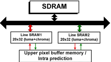
An architectural choice advocated for dealing with long past history of data is a memory hierarchy [12]. In the intra prediction, it utilizes the neighboring pixels to create a reliable predictor, leading to dependency on a long past history of data. This dependency can be solved by storing upper rows of pixels for predicting current pixels but is a challenging issue in implementation cost and access bandwidth. To optimize the introduced buffer cost and access efficiency, we use two internal Line SRAM1 and Line SRAM2 to store the Luma and Chroma upper line pixels, as illustrated in Figure 1. By the ping-pong mechanism, the upper neighboring pixels of current MB (or MB pair) are stored to one of them, and the other Line SRAM is used to store next MB of upper neighboring pixels. This memory hierarchy facilitates the internal Line SRAM size and the decoding pipeline schedule.
三、 研究方法及成果
A. The Embedded Compressor/Decompressor (1) Proposed Embedded Compression Algorithm (i) Algotrithm
The compression is conducted on a 4x4 pixel matrix (128 bits) obtained from the output of deblocking filter, and the compression ratio is fixed at two. Each 4x4 unit will become a 64 bits package after compression. Fixed compression ratio leads to constant amount of the coded data, so this EC scheme ensures the ability of random access without extra memory to record the segment address of coded data. Moreover, the 4x4 block unit is the basic coding unit in H.264 standard, and makes the data access in an efficient way.
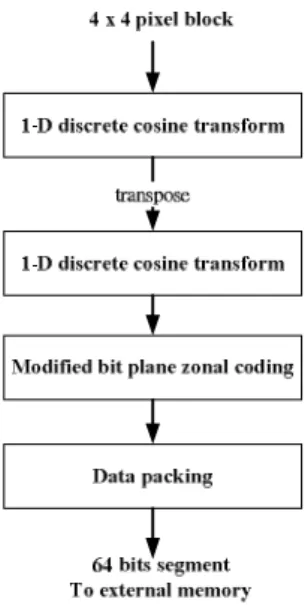
Figure 2 shows flowchart of the proposed algorithm. The overall compression scheme is formed by two parts: 1) two dimensions discrete cosine transform (DCT) and 2) modified bit plane zonal coding (MBPZ). Two dimensions DCT is composed by two one dimension, 4 points DCT. The discrete cosine transforms is a technique for converting a signal into elementary frequency components and it is widely used in image compression. For human visual system, human eyes are more sensitive on low frequency component of a picture and less sensitive on high frequency component. The DCT can gather the relative important low frequency signal on up left corner, and the most high frequency in down right corner. Thus the DCT combines with bit plane zonal coding with original point at up left corner can efficiently collect the information.
Figure 2: Flowchart of the proposed embedded compression algorithm
The second part is to perform modified bit plane zonal coding on 16 coefficients output from DCT. First, we reverse those negative coefficients into positive value and mark a “1” at the same position of sign bit plane. Sign bit plane can be considered as union of sign flags for each coefficient.Second, to improve the coding efficiency, we record the start plane. Search each bit planes from MSB to LSB (not including sign bit plane), and the first plane contains nonzero bits is the start plane. To avoid adding too much extra cycles and to simplify the hardware complexity in system view, we use one simple type only for recording each bit plane, though other complex types which can be more scrimping on bit using do exist. For each bit plane, we simply record the maximum row (RMAX) and column (CMAX) which have a “1” in this row or column, and then pack the bits in this zone which is enclosed by RMAX and CMAX. 4 bits are used to record RMAX/CMAX of each plane. And then, we packed the sign bit plane. Since we have only 64 bits budget for each 4x4 unit, the situation of unable to pack all the information may be happened frequently. Since not every coefficient can be packed, packing whole sign bit plane may become a waste. So we take the maximum value of RMAX and CMAX out of each packed bit plane and packing useful sign bits only by using those two boundaries. Under this method we
will not waste extra bits to pack those unused sign bits, and the RMAX/CMAX of sign bit plane need not to be packed since they can be derived from the previous coded information. Finally, the end plane needs to be estimated and packed to specify when to stop.
(ii) Packing Mechanism
The overall packing scheme is introduced in this part. After doing discrete cosine transform, we get 16 coefficients from each 4x4 block. There are 15 AC coefficients and one DC coefficient. Sine DC coefficient is the average value and is the most important in transform, we reserve 8 bits budget for the DC coefficient of every 4 x 4 block. DC coefficient is always positive, so we don’t have to worry about the sign bit for DC coefficient. For the rest 15 coefficients, we first packed the start plane and end plane (6 bits total). Then, we separate RMAX/CMAX and plane content of those planes which are between start plane and end plane, and connecting all the RMAX/CMAX together and all plane content together respectively. Sign bit information is inserted between the CMAX/RMAX and the plane content. Figure 3 shows the compressed segment format.
Figure 3: Flowchart of the proposed embedded compression algorithm
(2) Hardware Design
(i) Discrete Cosine Transform
The hardware design of DCT is referred from Lee’s architecture [5]. This architecture can maintain the same performance with original DCT while reduced the number of multiplications to about half of those required by the existing efficient algorithms. This design allows us to take the advantage of DCT while not suffering
from its hardware complexity.
(ii) Modified Bit Plane Zonal Coding and Data Packing
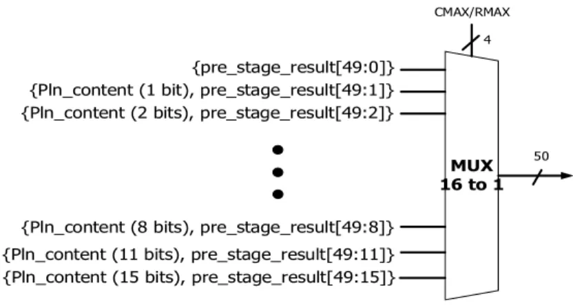
There is a combinational block dealing with coefficients to derive the RMAX/CMAX and plane content of each plane. To serialize the plane information in one cycle, we propose the content adaptive ripple architecture to solve the problem. The basic concept is shown in Figure 4. The 11 lines at left represent the 10 plane contents pulsing 1 sign bit plane content. Each circle represents a 16 to 1 MUX controlled by 4 bits RMAX/CMAX and is shown in Figure 5. By the ripple behavior, the wire at the end of the flow is the connected result. Notice that we embedded this compressor into our 108MHz decoder, thus one cycle time is enough to finish our ripple processing. CMAX/RMAX_sign Connected result Plane content_1 Plane content_2 Plane content_3 Plane content_4 CMAX/RMAX_10 CMAX/RMAX_3 CMAX/RMAX_2 CMAX/RMAX_4 CMAX/RMAX_9 Plane content_10 Plane content_9
Sign bit plane content
Figure 4: Context adaptive ripple architecture
{Pln_content (15 bits), pre_stage_result[49:15]} {Pln_content (11 bits), pre_stage_result[49:11]} {Pln_content (8 bits), pre_stage_result[49:8]}
MUX 16 to 1
CMAX/RMAX
{pre_stage_result[49:0]} {Pln_content (2 bits), pre_stage_result[49:2]} {Pln_content (1 bit), pre_stage_result[49:1]}
50 4
Figure 5: The MUX structure (iii) Encoder Design and Decoder Design
Figure 6 shows the pipeline architecture of compressor design. Since compressor has more time to handle the encoding process, we use three stages here and each stage needs 4 cycles. This design with longer cycles can shrink the gate count by reducing one dimension four points DCT units. Under this design, a MB needs 72 cycles to encode.
Figure 6: Encoder architecture
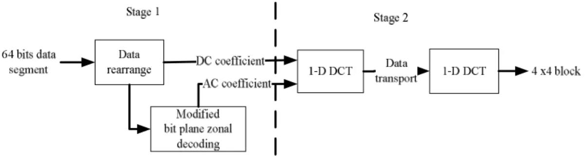
Figure 7 shows the architecture of decompressor. To provide data for motion compensation unit suitably, the decompressor must support higher throughput inevitably. The decompressor is divided into two stages and each stage needs 2 cycles, a 4x4 block needs 4 cycles to decode, including the data-fetching. Decoding a MB just needs 34 cycles.
Figure 7: Decoder architecture
(3) Integration with H.264 Decoder
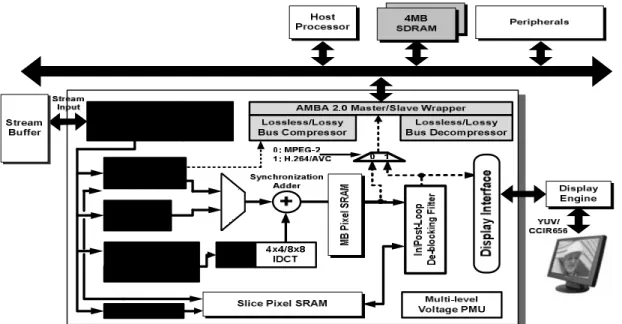
Figure 8 shows the block diagram of the H.264 video decoder containing an embedded compressor. Embedded compressor works as the interface between decoder
IP and external memory. And the EC mechanism is ready to be used by adding extra address control logic. Since the compression ratio of our embedded compressor is two, each data is compressed into half of the original size. The address control logic is very easy to implement.
Figure 8: H.264 decoder architecture with proposed embedded compression algorithm
The H.264 decoder works at 108 MHz, performing the HD1080i@30fps. The EC compress the data from deblocking filter, and 4x4 blocks will become 64 bits segments and then stored into off-chip memory. Thus, the data access times of off-chip memory are half of the original access times for the system without an embedded compressor. The embedded decompressor decompresses data from external memory and sends them to motion compensation unit. The system bus bandwidth is default as 32 bits and the external memory is 32 bits per entry, so the original system takes 4 pixels as accessing data unit. The access behavior of motion compensation with/without embedded compressor can be analyzed as follows. If the requested 4x4 blocks are perfectly aligned with the coded 4x4 blocks, only 2 cycles are needed to fetch the 4x4 block while the original system needs 4 cycles to fetch. For the needed
block not aligned with the coded blocks in only one direction, the system with embedded compressor needs to decode two blocks to derive the needed data, so 4 cycles are needed. The original system, taking 4 pixels as accessing unit, needs 4 cycles to fetch data. For the needed 4x4 block not aligned with the coded data in both vertical and horizontal directions, the system with EC needs decoding four 4x4 blocks and 8 cycles are needed for data fetching. The original system needs 8 cycles too. For the final situation, the sub pixel case, a 4x4 block needs a 9x9 pixels block to finish the motion compensation. 18 cycles is needed for EC while original system needs 27 cycles. From the analysis above, we can see that H.264 decoder with an embedded compressor does reduce the access times and can efficiently reduce the access power consumption.
(4) Evaluation Result
Software implementation of the proposed algorithm is integrated with JM12.4. The reference frame is compressed by the proposed algorithm and compared with the result of previous work using MHT and GR coding respectively. The test sequences are Foreman, Stefan, Mobile and Akiyo in CIF format and Station in HDTV format. All sequences are organized in one I frame follows nine P frames format. For each sequence, 100 frames are used to compute the average PSNR value reference to the original sequences.
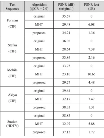
Table 1 is the simulation result of five sequences and shows the performance of original H.264 decoder without any recompression, embedded with MHT and embedded with our proposed algorithm.
Table 1: PSNR comparison Test Sequence Algorithm (@CR = 2.0) PSNR (dB) (original ) PSNR lost (dB) original 35.57 0 MHT 29.48 6.08 Forman (CIF) proposed 34.21 1.36 original 36.02 0 MHT 28.64 7.38 Stefan (CIF) proposed 33.86 2.16 original 33.75 0 MHT 23.10 10.65 Mobile (CIF) proposed 29.27 4.48 original 39.64 0 MHT 32.17 7.47 Akiyo (CIF) proposed 38.33 1.31 original 38.85 0 MHT 32.97 5.88 Station (HDTV) proposed 37.13 1.72
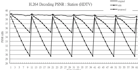
The proposed method maintains better quality in slow motion sequences than high motion sequences. However, performance of the proposed method in all sequences is better than previous MHT work. The average PSNR degradation of proposed method is 2.21dB while the MHT is 7.5dB. Figure 9 shows the embedded result with Station sequence in HDTV format. Although the quality drop is inevitable, the proposed method efficiently slows down the speed of decay than previous MHT work.
H.264 Decoding PSNR : Station (HDTV) 28 29 30 31 32 33 34 35 36 37 38 39 40 1 3 5 7 9 11 13 15 17 19 21 23 25 27 29 31 33 35 37 39 41 43 45 47 49 51 53 55 57 59 61 frame number P S NR ( dB ) original mht proposed
Figure 9: Simulation result of Station sequence(HDTV)
B. The High Profile Intra Predictior
(1) Proposed High-Profile Intra Predictor
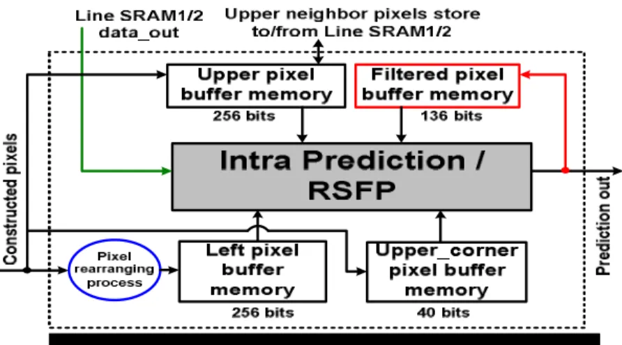
Figure 10 shows the block diagram of the proposed high-profile intra compensation architecture. A pixel rearranging process, which is located on the bottom-left of Figure 10, is proposed to reduce the complexity of neighbor fetching when MBAFF coding is enabled. The signal, Line SRAM1/2 data_out, is directly connected to the intra prediction block for replacing the last set of upper buffer memory. As for 8×8 intra coding, a dedicated pixel buffer memory is used to store the filtered neighboring pixels and reuse the overlapped pixel data. According to the relations between Luma intra_8x8 modes and numbers of filtered pixels which are needed in each mode, we minimize the number of stored pixels to 17 (i.e. 136 bits). The output of predicted pixel is interfaced to the filtered pixel buffer memory because RSFP is embedded in the intra prediction generator.
Figure 10: Block diagram of the proposed high-profile intra predictor. (2) MBAFF Decoding with Data Reuse Sets
MBAFF is proposed to improve coding efficiency for interlaced video. However, it introduces longer dependency than conventional frame-coded picture. In this section, we analyze and realize it via upper, left, and corner data reuse sets (DRS) to reuse the pixels and improve the cost and access efficiency.
(i) Upper DRS
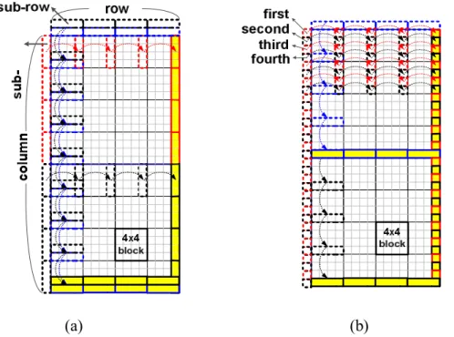
For decoding an MBAFF-coded video, upper buffer memory is used to store the constructed upper pixels of current MB pair. These upper buffers are updated with the completion of prediction process on every 4×4 block. For each updated sub-row(s), they can be reused by the underside 4×4 blocks. According to the different prediction modes of MB pair, the upper buffer will store data from different directions. If current MB pair is frame mode, it only needs to load one row of upper buffer (16 pixels) at first, and when a 4×4 block is decoded, updating the two sub-rows in two rows (8 pixels) of upper buffer from top to down at one time, as illustrated in Figure 11(a). In Figure 11 (b), a field-coded MB pair needs to load two rows of upper buffer (32 pixels), two times of frame-coded MB pairs. Then, only one sub-row of upper buffer memory will be updated when a 4×4 block is decoded. However, considering the fifth 4×4 block, it still needs a sub-row of upper buffer to predict, as shown in Figure 12.
In order to reduce the upper buffer memory size, the Line SRAM data_out is directly used. The only penalty to this scheme is that the Line SRAM data_out must hold the value until fifth 4×4 block is decoded.
(a) (b)
Figure 11: The updated direction of upper/left buffer memory in (a) frame and (b) field mode MB pair.
Figure 12: Line SRAM data_out replaces the last sub-row of upper buffer.
(ii) Left DRS Upper DRS
The updated direction of the left buffer is similar to that of the upper one. The direction ranges from left to right. When the left buffer is located on the right hand side of MB pair, the next MB pair can reuse these new pixels for the following prediction procedures. However, when the modes of current and previous MB pairs
are different, the left neighbors of a 4x4 block will become complicated. To reduce computational complexity of this intra predictor, pixel rearranging process is exploited. If current MB pair is frame mode, each sub-column of left buffer will be updated when each 4x4 block is decoded. On the other hand, if current MB pair is field mode, first and third buffers in each sub-column of left buffer will be updated when each 4×4 block is decoded in the top MB. Second and fourth buffers in each sub-column of left buffer will be updated when each 4×4 block is decoded in bottom MB. Hence, we only need to consider what the mode current MB pair is instead of handling four coding modes for the combination of current and previous MB pairs, and therefore the complexity can be reduced.
(iii) Corner DRS Upper DRS
Using corner buffer memory can efficiently reuse the upper left neighboring pixels. We change the positions of corner buffer from left [5] to top. Therefore, the total corner buffer size can be reduced by 38% (i.e. 64bits 40bits, because the MB number in horizontal is less than that of vertical MB pair). In particular, Figure 13 shows the updating directions of corner buffer. However, because the upper neighboring pixels will be either the last row or the row prior to the last row in upper MB pair, so the first corner of current MB pair has two processing states: reuse and reload. The first corner is reused when 1) the mode of current MB pair is identical to that of previous (left) MB pair or 2) before decoding the bottom MB of frame-coded MB pair. On the other hand, the first corner is reloaded when 1) the current MB pair has the different modes as previous (left) MB pair or 2) before decoding the bottom MB of field-coded MB pair. In summary, using neighboring buffer memory and their different directions of updates according to different modes of MB pair can reuse the neighboring pixels and improve the access efficiency. The associated pipeline
structure of MBAFF decoding is shown in Figure 14. We can see that during a MB pair decoding process, the interaction between buffers and Line SRAM can be completed easily and efficiently, and the communication between another Line SRAM and external SDRAM can be done at the same time.
Figure 13: The updated direction of corner pixel buffers.
Figure 14: The pipeline scheme of MBAFF decoding
(3) Intra 8x8 Decoding with Base-Modes
Luma intra_8x8 is an additional intra block type supported in H.264 high profile. Before decoding an intra_8x8 block, there is an extra process that is different from intra_4x4 and intra_16x16, which called reference sample filtering process (RSFP). Original pixels will be filtered first, and then using these filtered pixels to predict
subsequent 8×8 blocks. For an intra_4x4 and intra_8x8 block, 13 neighbors and 25 filtered neighbors are needed, respectively. According to the Luma intra_8x8 modes, the maximum number of filtered neighbors is 17, as illustrated in Table 2. Hence, only 17 (i.e. 136 bits) filtered pixels need to be stored. In the intra_4x4 process, the prediction formula of each mode except DC mode has the same form:
prediction_out = (A+2B+C+2) >> 2.
Compared with the share-based intra prediction generator [8]-[10], the proposed base-mode predictor not only reduces area cost (due to elimination of four adders) but also guarantees that four predicted pixels will be generated in one cycle of each intra_4x4 modes, including DC mode. In particular, we use this base mode predictor to generate the four predicted pixels in one cycle. In the RSFP, the form of formula is identical to that in intra_4x4, and also can be rewritten to the same form:
filtered_out = (A+2B+C+2) >> 2.
Hence, we can share the hardware resource to generate filtered pixels, as shown in Figure 15(a). Notice that an additional process, neighbor distribution, is needed to add in intra_8x8 process because we only store 17 filtered pixels instead of 25.
Table 2: Numbers of filtered pixels in intra 8x8 modes
Prediction Modes of Intra_8x8
# of filtered neighbors
0 (Vertical) 8
1 (Horizontal) 8
2 (DC) 0,8,16
3 (Diagonal down left) 16 4 (Diagonal down right) 17
5 (Vertical right) 17 6 (Horizontal down) 17 7 (Vertical left) 16 8 (Horizontal up) 8 - -M M N M M N Extra latency P P P P , where 0, 8, 16, 17 0 6 4 M or N or P (1)
In a four-parallel intra prediction module, the latency of an 8x8 block will be increased to 0~5 cycles according to the different modes of 8×8 blocks. In order to reduce the latency penalty, we reserve filtered pixelswhen the mode of the first/third is equal to 3 or 7 and second/fourth 8x8 block is equal to 0, 2 (if upper is available), or 3~7 (i.e. the value N = 6. Otherwise, N = 0). Then these filtered pixels are directly used to predict second/fourth 8×8 block. To clarify the extra latency, Eq. (1) lists the decoding extra latency in an intra_8x8 MB, and Table 2 summarizes the # of filtered pixels in each 8×8 intra coding mode (i.e. the value of M). In particular, we list some examples to clarify the processing behavior of an intra 8×8 block in Figure 15(b). If the modes of first and second 8×8 blocks are 3 (diagonal bottom left) and 7 (vertical left) or 3 (diagonal bottom left) and 4 (diagonal bottom right), only 10 and 11 pixels are needed to be filtered while decoding the second 8×8 block, as described in Figure 15(b).
(a)
(b)
Figure 15: (a) Architecture of an intra 8×8 decoding module, and (b) behavior of shared filter.
(4) Simulation Results
To enhance system performance, our proposal is designed to optimize area, buffer size, and latency. We use two 0.64kb Line SRAMs which are connected to a 32-bit system bus to make decoding pipeline simple, and 0.688kb SRAM to store reused neighboring pixels. Table 3 shows the average cycles for decoding an I-MB in different video sequences of our proposed design for 30fps HD1080 video format at working frequency of 100MHz with MBAFF and Luma intra_8x8. The overhead of latency is less than 5% compared to preliminary architecture [11]. The overall area and buffer memory size for supporting H.264 BP/MP/HP are 14063 gates in UMC 0.18um technology and 688 bits, as shown in Table 4. The overheads for supporting Luma intra_8x8 are 10% and 7.5% compared to [10].
Table 3: The average cycles for different video sequences. Test Video Sequence Intra Prediction @ BL [11] Proposed Intra Prediction @ HP Cycle Overhead Foreman 342.68 355.81 3.8% Grandma 275.63 285.28 3.5%
Suzie 294.90 307.28 4.2%
Table 4: Comparison results
Chen et al. [10] Proposal Overhead
Profile MP HP
Process 0.18um 0.18um
Working Frequency 87M 100M Gate Count 12785 14063 10% Memory (bit) 640 688 7.5%
四、 結論與討論
The objective of this project contains two topics: (1) the embedded compressor/decompressor, and (2) the high profile intra predictor. We described as below:
First, we proposed a flexible algorithm which achieves good coding efficiency and is suitable to be integrated with any video decoder. The proposed architecture is synthesized with 90-nm CMOS standard-cell library. The operation frequency is 108 MHz. The gate counts of proposed algorithm for compressor/decompressor are 15.8K/14.2K respectively. With the help of this embedded compression engine, we can reduce the bandwidth requirement and the external frame memory size. The proposed architecture costs 30K gate counts and deals with a 4x4 block unit while MHT costs 20K gate counts in dealing with a 1x8 pixels array. The proposed algorithm not only gains 5.29dB in picture quality but also achieves an area-efficient hardware implementation.
Second, we propose a high-profile intra predictor to support MBAFF and Luma intra_8x8 decoding. The proposed memory hierarchy includes upper, left and corner memory buffer which reuses the neighboring pixels for follow-up prediction procedures. In Luma_8x8 decoding process, we propose base-mode predictors to minimize the additional hardware cost, latency penalty, and filtered pixel buffer memory size. Compared to the existing design [10] without supporting intra 8x8 coding, this design only introduce 10% and 7.5% of gate counts and SRAM overheads. The proposed design can achieve real-time processing requirement for HD1080 format video in 30fps under the working frequency of 100MHz.
五、 參考文獻
[1] R. J van der Vleuten et al, “Low-complexity scalable DCT image compression”, IEEE Proc. Image Processing, vol.3 pp. 837-840, Sep. 2000
[2] Yongje Lee; Chae-Eun Rhee; Hyuk-Jae Lee; “A New Frame Recompression Algorithm Integrated with H.264 Video Compression” Circuits and Systems, 2007. ISCAS 2007. IEEE International Symposium, pp. 1621-1624, May 2007 [3] A. Bourge and J. Jung, “Low-Power H.264 Video Decoder with Graceful
Degradation,” SPIE Proc. Visual Commun. and Image Process., vol. 5308, pp. 1234-1245, Jan. 2004
[4] T.-Y. Lee, “A New Frame-Recompression Algorithm and its Hardware Design for MPEG-2 Video Decoders,” IEEE Trans. CSVT, vol. 13, no. 6, pp. 529-534, June 2003.
[5] Byeong Lee, “A new algorithm to compute the discrete cosine Transform” Acoustics, Speech, and Signal Processing, IEEE Transactions on Volume
32, Issue 6, pp:1243-1245, Dec 1984
[6] Joint Video Team, Draft ITU-T Recommendation and Final Draft International Standard of Joint Video Specification, ITU-T Rec. H.264 and ISO/IEC 14496-10 AVC, May 2003.
[7] T. Wiegand, G. J. Sullivan, G. Bjontegaard, and A. Luthra, “Overview of the H.264/AVC video coding standard,” IEEE Trans. on Circuits and Systems for Video Technology, vol. 13, no. 7, pp. 560–576, July 2003.
[8] Yu-Wen Huang, Bing-Yu Hsieh, Tung-Chien Chen, and Liang-Gee Chen, “Hardware architecture design for H.264/AVC intra frame coder”, ISCAS 2004. [9] Esra Sahin and Ilker Hamzaoglu, “An Efficient Intra Prediction Hardware
Architecture for H.264 Video Decoding”, DSD 2007.
[10] Jia-Wei Chen, Chien-Chang Lin, Jiun-In Guo, and Jinn-Shyan Wang, “Low Complexity Architecture Design of H.264 Predictive Pixel Compensator for HDTV Application”, ICASSP 2006.
[11] Ting-An Lin, Sheng-Zen Wang, Tsu-Ming Liu and Chen-Yi Lee, “An H.264/AVC Decoder with 4x4 Block-Level Pipeline,” Proc. ISCAS, pp. 1810-1813, May, 2005.
[12] Tsu-Ming Liu and Chen-Yi Lee, “Design of an H.264/AVC Decoder with Memory Hierarchy and Line-Pixel-Lookahead,” Journal of VLSI Signal Processing Systems, Aug. 2007.
六、 計畫成果自評
在此計畫執行第一年中,我們提供兩個可應用於行動通訊之下世代低功耗視
訊解碼器元件,其中分別為:
(1) A novel Embedded Bandwidth-Aware Frame Compressor for Mobile Video Applications
(2) Design of An Intra Predictor with Data Reuse for High-Profile H.264 Applications 表九簡列此計畫支持本研究群的相關研究成果,其中,有 9 件國內、外專利 申請中、22 篇國際期刊與會議論文已發表於 IEEE,本研究群亦十分感謝國家科 學委員會今年暨未來的持續支持與鼓勵。 Table 5: 本計畫近年(2007-2009)研究貢獻 成果項目 96.01.01-98.05.31 成果項目 96.01.01-98.05.31 國內(件數) 4 國內(件數) 0 國外(件數) 5 國外(件數) 9 申請 國內外合計件數 9 期刊 國內外合計件數 9 國內(件數) 0 國內(件數) 0 國外(件數) 0 國外(件數) 13 專 利 獲得 國內外合計件數 0 論文 研討會 國內外合計件數 13