Abstract—The fields of multimedia and wireless communi-cations have grown rapidly in recent years, leading to a great demand for an image-coding scheme that has both compres-sion and error-resilient capabilities. Because bandwidth is a valuable and limited resource, the compression technique is applied to wireless multimedia communication. However, strong data dependency will be created while the bit-rate reduction is achieved. Transmission errors always results in significant quality degradation. In this paper, an error-resilient image coding for discrete-cosine-transform-based image compression is proposed. It can successfully prevent errors from propagating across image block boundaries with little overhead. Additionally, a novel post-processing error concealment scheme is presented to retain low-frequency information and discard suspicious high-frequency information. Low-resolution information, rather than total corruption, can be obtained during the image-decoding process. Because of low complexity and latency properties, it is very suitable for wireless mobile applications. Simulation results show that good image quality(PSNR = 31 78dB) and a low fraction of corruptive blocks (less than 5%) can be achieved even when the bit error rate is 0.1%.
Index Terms—Discrete cosine transform (DCT), error resilient, image coding, synchronization, VLC.
I. INTRODUCTION
W
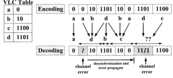
IRELESS multimedia transmission has become increas-ingly popular in recent years. Channel bandwidth is a valuable and limited resource, and so compression techniques for reducing the data rate are applied. However, a strong data dependency always occurs when the bit rate is reduced. Any transmission error over a wireless noisy channel can distort large areas of an image. A traditional method uses forward error-correcting (FEC) codes. But, adding redundant infor-mation compromises the compression rate. Moreover, FEC decoding latency is unacceptable for real-time applications. Many compression standards (JPEG [1], MPEG[2], H.261[3]) use variable-length coding (VLC) as entropy coding for further increasing compression rate. Because codewords have various lengths, error bits can cause decoder loss of synchronization. Errors may propagate for an uncertain distance until decoder is resynchronized. An example is given in Fig. 1. Several VLCs (B2-code, T-code[4], HVLC[5], and RVLC[6]) have beenpre-Manuscript received December 18, 2001; revised November 25, 2002. This paper was recommended by Associate Editor K.-H. Tzou.
The authors are with the Department of Electronics Engineering, National Chiao Tung University, Hsinchu 300, Taiwan, R.O.C. (e-mail: [email protected]).
Digital Object Identifier 10.1109/TCSVT.2002.808430
Fig. 1. Error propagation of VLC.
sented to reduce the error propagation distance. Although these VLCs can perform effective resynchronization, the following correctly decoded coefficients are shifted to inappropriate frequency bands.
Another popular approach is to periodically insert a synchro-nization marker (SM) into the bitstream. Synchrosynchro-nization can be regained when a valid SM is detected. However, SMs cannot be inserted frequently since they significantly increase the re-dundancy. Recently, error-resilient entropy coding schemes [7] have been proposed. They reorganize blocks of various lengths into fixed-length blocks to prevent propagation of errors. The decoder can synchronize each image block with a low overhead. However, much computation power and a large memory buffer are required. In [8], the amount of data in each image block is transmitted as side information. Thus, the decoder can use this information for block synchronization. A coding scheme is pro-posed for DCT-based image compression that can prevent errors from propagating across the block boundary with an acceptable overhead. Additionally, an efficient post-processing error-con-cealment scheme is presented to recover usable data from er-roneous blocks. Hence, a low-resolution image, rather than a totally corrupted image, can be restored.
This paper is organized as follows. Section II describes the error-resilient coding structure. In Section III, we present the post-processing error concealment scheme. Simulation results and performance comparison are given in Section IV. Finally, we provide our conclusion in Section V.
II. DATASTRUCTURE OFERROR-RESILIENTIMAGECODING
Based on DCT-based image compression, an error-resilient image coding scheme is porposed to prevent errors from prop-agating through block boundaries. Thus, a high quality image can be obtained. Besides, dc coefficients should not be mutually dependent. A fixed-length code (FLC) is used to encode dc
Fig. 2. Error-resilient image-coding bitstream structure.
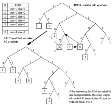
coefficients that are different from the JPEG predictive coding scheme. For ac coefficients, the JPEG run/size-magnitude coding scheme is applied. Only certain codeword patterns are changed. The encoded bits of each image block are recorded as block alignment information (BAI). These BAI data are protected by RS codes and are sent as side information. The added redundancy is less than 1% (160 bytes); 8 bytes of erroneous data can be correctly recovered. Here, all burst errors are assumed to be no longer than 64 bits. Accordingly, BAI data can be received correctly for block synchronization. Fig. 2 depicts the proposed image-coding scheme. Each block consists of a fixed-length dc and run/size-magnitude VLC codewords. End-of-block (EOB) symbols can be removed since BAI can be simply used to align the block. After the EOB symbol is removed, the VLC table is reorganized to further improve the compression rate, as shown in Fig. 3.
The BAI data size must be minimized to reduce total redun-dancy. Generally, the unit of BAI can be set from 1 bit to bits. When the block size is not an integer number of BAI units, dummy bits are inserted to fill the gap. The number of dummy bits can be reduced if a small BAI unit is used. Here, the max-imum data size of each image block is defined as bits and the size of the BAI unit is bits. The BAI wordlength becomes K-B bits. Because various dummy bits insertions have equal probability, dummy bits are required to fill the gap. Table I analyzes BAI overheads. The optimal overhead is obtained with a BAI unit of either 2 or 4 bits. A large BAI unit is preferred to minimize the FEC redundancy. Image locality char-acteristic causes most neighboring blocks to have similar sizes and information. The predictive coding scheme can be exploited to reduce further the BAI overhead. If the data sizes of two con-secutive blocks are similar, only the difference between them is encoded.
III. POST-PROCESSINGERRORCONCEALMENT
An efficient post-processing error-concealment scheme is very useful in recovering images of high quality. When an erroneous block is detected, a decoder can retrieve information by predicting the probable correct data. In run-length coding, an incorrect “run” value shifts all the following ac coefficients to inappropriate frequency bands. Even though it can be resyn-chronized quickly, image quality is degraded, as illustrated in Fig. 4. Since errors do not always occur at the beginning of an image block, some error-free coefficients probably exist. These
Fig. 3. JPEG run/size ac symbols reorganization. TABLE I
BAI OVERHEAD ANDNUMBER OFDUMMY
BITSINSERTEDWITHVARIOUSBAI UNITS
Fig. 4. Low-resolution image retrieving. The run/level (the level is the quantized value) symbols shown on the right side of each image form the related images after performing inverse-quantize and IDCT.
coefficients are to be retrieved and suspicious coefficients are discarded. Accordingly, a low-resolution image, rather than a totally corrupt image, can be restored, as shown in Fig. 4(d). This is the main concept that underlies the proposed smart-IDCT post-processing error-concealment scheme.
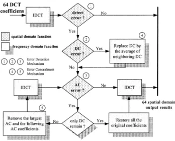
Fig. 5. Post-processing error-concealment decoding flow.
The post-processing error-concealment decoding flow is de-picted in Fig. 5. After IDCT, a simple error-detection scheme is used to check each image block. If no error is detected, the image block will be output normally. Otherwise, error-conceal-ment flow is applied to fix the block. The erroneous dc and ac coefficients can be detected separately. First, the dc coefficient is checked. If it is erroneous, it will be replaced by the average dc value of the neighboring blocks. Then, the following ac co-efficients are checked. If the ac coco-efficients are contaminated, the largest ac value and the following coefficients in zig-zag scanning order are removed. These ac values always dominate the visual pattern and so are removed to extract an acceptable low-resolution image. Then, IDCT and ac error detection are performed again. These error-detection and removal procedures are repeated until either no ac errors are detected or all ac coeffi-cients have been deleted. If these procedures are executed until only a dc coefficient remains, then all ac coefficients are restored and output. Consequently, only suspicious high-frequency in-formation is discarded, which is less visible to the human eye. The efficiency of error detection determines the performance of the scheme. More accurate detection of errors can recover better image quality. Practically, an optimum solution is hard to find. Pseudocodes of the post-processing error-concealment proce-dure are provided below.
Check:
reset poscounter and negcounter; for (i=0;i<64;i++){
if(array[i] > MAXvalue) poscounter++; else if(array[i] < MINvalue) neg-counter++;}
if (poscounter + negcounter < THRESHOLD) return; // assume block has no error, process end !!
else Goto Repair; // processing error con-cealment
endCheck Repair:
Fig. 6. Dc and ac error detection.
if (poscounter==0 k negcounter==0) { // as-sume dc error
array[0]=avg(array_neighbor[0]); // re-place dc by neighbor dc average value
IDCT(array);
Goto Check;} // checking again after dc repairing
else { loop{
j = Position(max(Array)); // position of the largest ac coefficient
if (j=0){ // remove ac’s until remaining dc, return original array
IDCT(array); return;} // process end !! else {
for(i=j; i < 64; i++)
array[zigzag[i]]=0; // remove the largest coefficient and the following coefficients
IDCT(array);
Goto Check;} // checking again after ac’s removing
}}
EndRepair
In a gray-level image, all pixel values are always within the range from 0 to 255. After compression and decompression, certain pixel values may exceed this range due to distortion by quantization and fixed-point operations. An image block is mostly erroneous if too many pixels have abnormal value. This feature is exploited to detect error. After IDCT, the number of abnormal pixel values in each block is counted. If the number exceeds a given threshold, the block will be declared erroneous and be passed through the error concealment flow. Based on large amount experimental results, the threshold value is set here to five. An erroneous dc results only in variation in brightness because it is coded by FLC. If the variation is small, then the distortion is negligible. Otherwise, serious brightness variation
Fig. 7. Retrieved image after post-processing error concealment.
Fig. 8. RD curves comparison of different approaches.
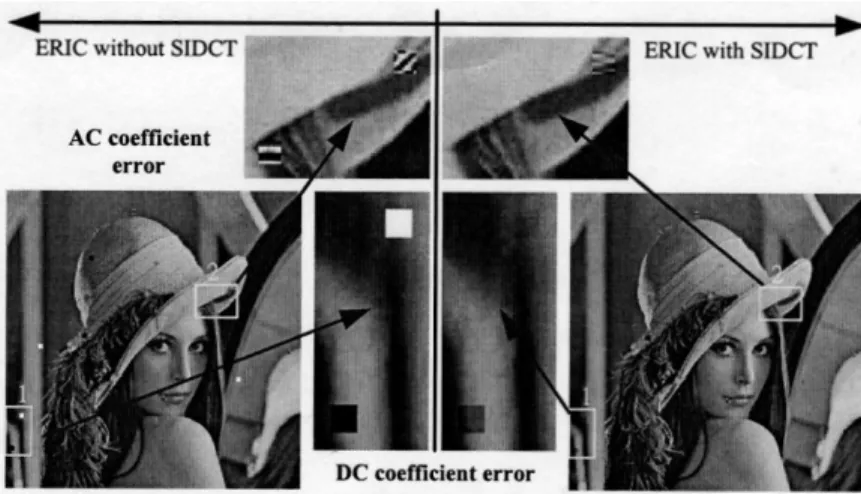
may overwhelm ac patterns. Fortunately, this situation can be detected easily. Fig. 6 shows the effects of dc and ac errors after transformation into spatial domain. A dc error usually causes pixel values to exceed one valid range. However, ac errors al-ways cause both valid range boundaries to be exceeded. These phenomena are used to detect dc and ac errors.
A practical image result that results from applying the pro-posed post-processing error concealment scheme is shown in Fig. 7. The scheme can retrieve low-resolution images rather than a totally corrupted one. Although it does not fix all erro-neous image blocks, most of the conspicuously corrupted blocks are found and recovered. Consequently, the quality of the recon-structed image can be maintained. Other advanced error-detec-tion schemes can be applied to improve further the quality of the image since it is a post-processing procedure.
IV. SIMULATIONRESULTS ANDPERPORMANCECOMPARISON
More than 50 gray-level test images were simulated to evaluate the performance of the proposed scheme. Only simulation results for the “Lena” image are presented here. Fig. 8 compares the achieved compression rate with that obtained using other approaches. Detailed overhead analyses
TABLE II
OVERHEADCOMPARISON OF“LENA” IMAGE(35.5 dB)
are provided in Table II. Here, FEC redundancy is not included since it is less than 1%. The overhead of EREC [7] is very small and is thus always neglected. The effects of inserting different numbers of restart marker (SM) are also compared. For a color image, the overhead of [9] can be further reduced to 6% 9%, which is quite close to that obtained by applying the proposed approach. Certain blocks are grouped for error synchronization in [9]. The analysis shows that the overhead is only around 5%.
Fig. 9. PSNR performance comparison of different approaches.
Fig. 10. Fraction of corrupt blocks (PSNR<40dB) for various BER.
TABLE IV
PSNR PERFORMANCES OFPOST-PROCESSINGERRORCONCEALMENT
It is less than the other approaches. For various image qualities, the overheads are listed in Table III. Although the overhead of
Fig. 11. Reconstructed “Lena” image with 0.1% BER.
Fig. 12. Reconstructed “Pepper” with 0.1% BER.
Fig. 13. Reconstructed “Baboon” image with 0.1% BER.
EREC [7] is the lowest, it requires high computational power and a large memory buffer to reorganize the bitstream. It is not suitable for mobile applications.
Images are simulated with different bit error rates (BERs) to consider various channel conditions. The transmission error is either a random single-bit error or includes successive error bits. For the “Lena” image (35.5 dB), it compares the quality of the reconstructed image with other approaches in Fig. 9. The per-formance of EREC [7] is as high as 37 dB, since its error-free compressed image quality exceeds 37 dB. It is higher than our simulated image source. Although the basis is different, perfor-mance can be relatively compared. After post-processing error concealment is performed, the retrieved image quality can be further improved by approximately 3 dB, yielding up to 31.78 dB even at 0.1% BER. The recovered image quality strongly depends on the proportion of corrupt blocks. In [7], an image
block is assumed to be corrupted if its PSNR is less than 40 dB. The fractions of corruptive blocks are compared in Fig. 10. It shows that our proposed schemes can minimize corrupt blocks effectively. Some simulated performances are listed in Table IV. Certain image results are also given in Figs. 11–13.
The proposed image-coding scheme has both optimal redundancy and error-resilient capability. The proposed post-processing error concealment can retrieve high image quality even at high BER. No additional memory is required for its operations. Besides, the latency and complexity are much less than in [7] and [9].
V. CONCLUSIONS
Image transmission over a wireless channel requires higher error resiliency than required in other kinds of channel. An error-resilient image-coding scheme for wireless image transmission is proposed. It exhibits low redundancy, low complexity, and high error tolerance. It can prevent errors from propagating through block boundaries. Hence, image quality can be well maintained. Besides, an efficient post-processing error concealment scheme for recovering image quality is pre-sented. It is an IDCT post-processing procedure that removes suspicious erroneous information. Images can be restored with very high quality (31.78 dB), even at 0.1% BER. More-over, the fraction of corrupted blocks is less than 5%. These performances fulfill the requirements of wireless multimedia applications.
ACKNOWLEDGMENT
The authors would like to thank the reviewers for their com-ments and suggestions.
REFERENCES
[1] Digital Compression and Coding of Continuous-Tone Still Images, CCITT Recommendation T.81, 1992.
[2] ISO-IEC/JTC1/SC2/WG8/MPEG, MPEG Video Committee Draft, Dec. 18, 1990.
[3] Draft Revision of Recommendation H.261, Video Codec for Audiovisual
Services at p x 64kbit/s, CCITT Study Group XV, 1990.
[4] G. R. Higgie, “Self synchronizing T-codes to replace Huffman codes,” in Proc. IEEE Int. Symp. Information Theory, 1993, pp. 336–336. [5] Y.-S. Yew-San Lee, C.-M.Cheng-Mou Yu, W.-S.Wei-Shin Chang, and
C.-Y.Chen-Yi Lee, “HVLC: error correctable hybrid variable length code for image coding in wireless transmission,” in Proc. ICASSP’2000, vol. 4, 2000, pp. 2103–2106.
[6] Y. Takishima, M. Wada, and H. Murakami, “Reversible variable length codes,” IEEE Trans. Commun., vol. 43, pp. 158–162, Feb./Apr. 1995. [7] D. W. Redmill and N. G. Kingsbury, “The EREC: an error-resilient
tech-nique for coding variable-length blocks of data,” IEEE Trans. Image
Processing, vol. 5, pp. 565–574, Apr. 1996.
[8] Y.Yoo Youngjun and A. Ortega, “Constrained bit allocation for error resilient JPEG coding,” in Conf. Record 31st Asilomar Conf. Signals,
Systems & Computers, vol. 2, 1997, pp. 985–989.
[9] Y.-H.Yi-Huang Han and J.-J.Jin-Jang Leou, “Detection and correction of transmission errors in JPEG images,” IEEE Trans. Circuits Systems