rolling characteristics were observed and compared with the data from finite element simulation, which include diameter of workpieces after deformation, the pitch length and threaded angle of spiral marks, and the cavity at the leading end of rolled plasticine. The comparison confirms the correctness of the simulation model for PSW.
© 2003 Elsevier B.V. All rights reserved.
Keywords: Planetary three-roll; PSW; Plasticine workpiece
1. Introduction
Conventionally, most stainless steel rods are manufactured during the roughing rolling process, with a large reduction ratio by several two-high rolling mills. Six to eight conven-tional mills can be replaced by using one three-roll plane-tary rolling mill (Planetensh rägwalzwerk, PSW, as shown in
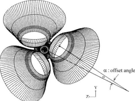
Fig. 1 [1]) in the roughing rolling process. The PSW mainly includes three conical rolls and an external ring. As shown in
Fig. 2, the rolls are inclined and are located equally around the axis of the workpiece, and the rolls’ axes intersect with that of the workpiece by an offset angle. This offset angle forces workpiece to move forward as the rolls rotate. The rolls are driven by a main motor through the planetary gear system and are positioned by the ring, which is driven by a secondary motor. The secondary motor drives the sun wheel of a planetary gear system as a superimposed driver to make the ring rotate in a direction opposite to that of the rolls. In addition to fixing the rolls, the main purpose of the ring attempts to eliminate any slight rotary motion of the rod in the mill [2] and to counteract the twisted deformation of the workpiece during rolling process, to help keep the rods round during rolling. Using a PSW reduces the operational cost, the maintenance and the space occupied in the plant. Moreover, the advantages of the PSW include flexibility of ingot size, low rolling load, low lateral spread of material
∗Corresponding author. Fax:+886-35-720-634. E-mail address: chhung@cc.nctu.edu.tw (C. Hung).
[3,4]and a low temperature drop between the leading and the tail end of the rolled bar[5]. These characteristics increase precision, and thus homogenize the quality and increase the competitiveness of the products.
Some research has addressed the three-roll planetary rolling process. Most experimental research involves the rolling experiments on an experimental three-roll rolling mill with plasticine as the working material, because of the difficulty of experiment on a real, operating mill. The material properties of plasticine are similar to those of stainless steel at elevated temperatures. Aoyagi and Ohta
[6] observed the flow of the material, the load and torque on the rolls, and the pressure distribution on the rolls dur-ing rolldur-ing process, with different cross-sectional reduction rates. Additionally, the effect of the offset angle on the exit velocity of the rods was determined. Nishio et al.[7]
discussed the quality characteristics of rolled products with different offset angles and roll profiles. Chen [8] designed a planetary three-roll experimental machine to confirm the possibility of rolling clay, plasticine, aluminum and lead, to determine the relationship between the rolling parame-ters and the spiral mark on the products after rolling. Shih et al.[9]developed a finite element model for the three-roll planetary rolling process and simulated the deformation of the stainless steel during rolling. The simulated results also compared to the results from Aoyagi’s experimental work.
However, the references specify no particular plasticine and configuration of experimental mill, the comparison has not yet been validated completely. Therefore, this work used 0924-0136/$ – see front matter © 2003 Elsevier B.V. All rights reserved.
Fig. 1. Cross-section of PSW[1].
the white plasticine as the working material on the planetary three-roll experimental machine and the experimental results were compared to those from the finite element simulation to verify the correctness of the simulation model.
2. Experiment on planetary three-roll experimental machine
2.1. Planetary three-roll experimental machine
The planetary three-roll experimental machine, fabricated by Chen [8], was designed to be able to roll aluminum.
Fig. 3shows the configuration of this experimental machine. The rolls of this machine are designed to reach a maximum reduction of 80%. The profile of the roll, shown inFig. 4, is formed with three straight lines and is divided into three zones.
Fig. 2. Roll of PSW (courtesy of Walsin Cartech specialty steel corpora-tion).
(1) Large deforming zone: provides the main deformation of the workpiece.
(2) Small deforming zone: deforms the workpiece to the final size.
(3) Smoothing zone: eliminates the spiral marks on the workpiece while maintaining accurately the size of the workpiece during rolling process.
The parameters of the experimental machine are consis-tent with the setup of a practical rolling mill and are speci-fied below:
• Inclined angle of roll (β): 53◦. • Offset angle of roll (α): 7◦. • Rotational speed of rolls: 2.35 rpm.
Both the rotational and revolution speed of the rolls are adjustable but in the experiments the revolution was sus-pended. Thus, the operational boundary conditions of the experimental machine were the same as those of the FEM model. The position of the rolls can be controlled so that the final diameters of the rolled workpiece can be changed. The maximum initial diameters of the workpieces were 60 mm, and the final diameters of the workpieces ranged from 32 to 20 mm after rolling.
2.2. Preparation of plasticine workpiece
Before conducting the rolling experiment on experimental machine, the plasticine workpieces were made first. The white plasticine manufactured by Peter Pan Playthings was selected as the working material. The commercial plasticine is packed in the form of a cuboid, which is composed of 25 long sticks. The sticks of plasticine were first heated to 40◦C to make them softer and easier to combine them together by repeatedly kneading. Few drops of oil were added into the kneading plasticine to provide higher adhesion. Having been repeatedly kneaded, cretin amount of plasticine was
Fig. 3. Configuration of planetary three-roll experiment machine[8].
put inside a pair of half-cylindrical molds and was then compressed to form an experimental rod. After compressing the mold tightly, the plasticine was fully filled the mold and the redundancy that extruded out the mold at both ends was removed. To fully fill the mold to increase the homogeneity
Fig. 4. Roll profile of the experimental machine[8](unit: mm).
Table 1
Configuration of experimental workpiecea
Initial diameter, D0 (mm) Final diameter, Df (mm) Area ratio, rA(%) 30 27 19 30 24 36 40 24 64 aArea ratio,rA(%) = ((D2 0− D2f)/D02) × 100.
of workpiece, the amount of plasticine was taken more than necessary.
Three types of the plasticine rods, 100 mm in length, were rolled.Table 1lists the initial and final diameters of these rods.
3. Finite element simulation of planetary three-roll experimental machine
3.1. Simulation model
The simulation model of the planetary three-roll exper-imental machine was established by following the proce-dures specified in the previous work that utilized equation of meshing to handle the boundary conditions[9]. The ge-ometrical specifications of the simulation model were the same as those of the experimental machine. Fig. 4 shows the profile of the rolls. The profile of workpiece was built corresponded to the cylindrical rod used in the experiments.
Fig. 5shows the mesh system of the complete setup and the workpiece.
The rolls are assumed to be rigid and isothermal and the heat transfer between rolls and workpiece is ignored. For
Fig. 5. Mesh system of the planetary three-roll experiment machine.
hot working, the typical coefficient of friction was found experimentally to beµ = 0.4[10]. Since the material prop-erties of plasticine are similar to those of steel at high temperature, the coefficient of friction in the interface be-tween the rolls and plasticine workpiece was assumed as µ = 0.5.
3.2. Material properties of plasticine
White plasticine was selected as the working material on the experiment. In the finite element analysis, the material properties of plasticine, such as yield stress and Young’s modulus, must be obtained first. The stress–strain relation-ship can be obtained either from the tensile test [11] or the compression test [12]. This study performed a com-pression test because of the large reduction during rolling processes. The plasticine, which was available after knead-ing procedure, was shaped into cylindrical specimens with both diameter and height of 25.4 mm. The true stress–true strain curve was obtained, and was fitted by a power law equation:
σ = 0.246ε0.183(MPa) (1)
This constitutive relationship was then used in the finite element simulation.
No.1 No.2 No.3 No.4 AVERAGE FEM
Number of Workpieces 20 21 22 23 24 25 26 27 28 29 30 Fi nal D iame te r(mm ) Area Ratio 19% 36% 64% Inclined Angle β=50 Offset Angle α=8
Rotational Speed of Rolls 2.35rpm
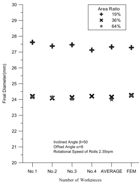
Fig. 6. Diameter of rolled workpiece.
4. Results and discussion
The experiments were performed five times for each area ratio. In Figs. 6, 10, 11 and 14, Arabic numerals in the abscissa axis indicate the number of the workpiece. 4.1. Diameter after deformation
The size of the products rolled from the planetary experi-mental machine is adjustable. Movable axes were design to adjust the position of rolls and thus maintain the symme-try of three rolls. Changing the position of rolls controls the final diameter of rolled workpieces.
After changing the position of roll, the diameter of work-piece after rolled is roughly obtained. Thus it is necessary to verify the final diameter. A workpiece was first rolled and then measured its diameter. If the diameter was not quali-fied, changing the position of rolls and the plasticine is rolled again. Repeat the above processes until the final diameter was confirmed to the required size.
Fig. 6shows the experimental results of final diameters. The figure shows that the results of each area ratio are very close but a little bigger than the original design. The dif-ference might result from the peak of the spiral marks and from the inaccurate adjustment in the position of rolls.
Fig. 6also shows the average of the diameter from ex-periment and compares to those from the simulation. This figure shows that the simulated results are close to the
workpiece is shown inFig. 7.
4.2. Characteristics of the rolled workpiece
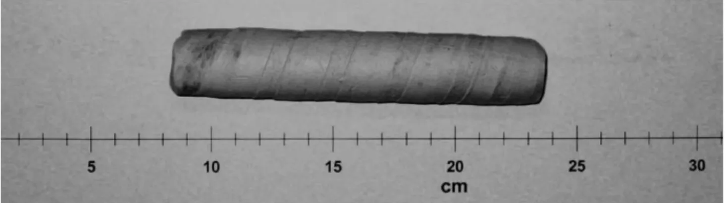
Fig. 8shows rolled workpieces with different area ratios. Conspicuous threaded marks are clearly seen on the surfaces.
Fig. 8. Rolled products.
ral marks were scored on the surface of the workpiece by the border between the small deforming zone and the smoothing zone of the rolls (Fig. 4). One spiral mark is more prominent than the other two because achieving per-fect symmetry of alignment of the three rolls is very dif-ficult.
Y
X x
∆
Φ
r
: Threaded Angle of Spiral Marks
x ∆
r
: Pitch of Spiral Marks
: Final Radius of Workpiece
Φ
Fig. 9. Characteristic of workpiece[7].
4.2.1. Pitch of spiral marks
Fig. 10shows the pitch length of the spiral marks obtained experimentally. Because the bending and twisting of rolled workpiece, the workpiece needs to be stretched slightly be-fore measurement. However, the shape of workpieces is still curved.
Above results also show that rods with the same final diameter after rolling (rA= 64% and rA= 36%) are scored
Fig. 10. Pitch length of the spiral mark.
with spiral marks of the same pitch length. Furthermore, for a given initial diameter (rA = 19% and rA = 36%), the pitch increases as the area ratio decreases.
During the simulation, the pitch of the spiral marks was determined from the locus of a point on the surface during the rolling process, yielding results similar to those obtained experimentally.Fig. 10indicates that the difference between the experimental results and simulation results is approxi-mately 2 mm. The figure also shows that rods with the same final diameter after rolling (rA = 64% and rA = 36%) are scored with spiral marks of the same pitch length. Further-more, for a given initial diameter (rA = 19% and rA = 36%), the pitch increases as the area ratio decreases. 4.2.2. Threaded angle of spiral marks
Fig. 11 presents the relationship between the threaded angle and the area ratio. The experimental data for each area ratio is close. Similar to the pitch length, the bending of rolled workpiece affects the threaded angle of the spiral marks. For the workpiece with a particular final diameter (Df = 24 mm, rA = 36% and rA= 64%), the threaded an-gle of the workpiece with area ratiorA= 36% is bigger than that withrA = 64%. And for rod with the same initial di-ameter (D0= 30 mm, rA= 19% and rA = 36%), threaded angle increase with the area ratio.
The FEM results in Fig. 11 show that rods with a par-ticular diameter after rolling (Df = 24 mm, rA = 36% and rA = 64%) have the same threaded angle of spiral marks
No.1 No.2 No.3 No.4 AVERAGE FEM
Number of Workpieces 50 52 54 56 58 60 62 64 66 68 70 Threaded Angle(degree) Area Ratio 19% 36% 64% Inclined Angle β=50° Offset Angle α=8°
Rotational Speed of Rolls 2.35rpm
Fig. 12. Characteristic of end cavity[7].
after rolling. For rods with the same initial diameter (D0= 30 mm,rA= 19% and rA= 36%), rolled workpieces with a smaller area ratio have a larger threaded angle. Addition-ally, the experimental results have the similar tendency and approximate magnitude as the simulated results. The dif-ference between the experimentally obtained data and the simulation results is about 2◦.
4.3. Inhomogeneous deformation of rolled rod
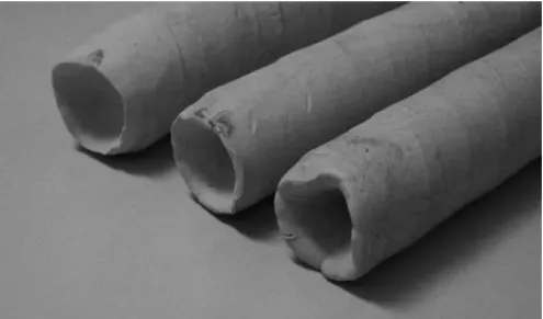
A cavity is always present at the leading end of tradition-ally rolled products, and the same is true for products rolled from the three-roll planetary rolling mill.Fig. 12illustrates the cavity of the rolled workpieces[7]. The rotation of rolls forces the workpiece to move forward and rotate around its own axis. This mechanism causes the velocity of material flow in the outer part of the workpiece to differ from that in the inner part. The outer part of the workpiece moves faster than the inner part and results in a cavity at the leading end of the rolled workpiece.Fig. 13shows the end cavity of the rolled plasticine rods.Fig. 14shows the depth of the cavity in the rolled plasticine increases with the area ratio.
If the plasticine is not kneaded uniformly and not fully filled the mold, the workpiece will not have homogeneous
Fig. 13. End cavity of the rolled workpiece.
No.1 No.2 No.3 No.4 AVERAGE FEM
Number of Workpieces 0 3 6 9 Inclined Angle β=50° Offset Angle α=8°
Rotational Speed of Rolls 2.35rpm
Fig. 14. Cavity depth on the workpiece.
properties, especially at both ends of the workpiece. The cavity of the leading end might be influenced, especially for workpiece with initial diameterD0 = 40 mm, because the homogeneity of the both ends could not be controlled easily for large workpiece. Thus the difference between the experimental data can be referred to the homogeneity on the leading end of the workpiece.
The pushing distance might be the another reason that af-fected the cavity depth. The workpiece must be pushed for-ward with certain distance to ensure sufficient contact area between the rolls and the workpiece. The distance should be identical to and depend on the size of workpiece. However, this distance may lack consistency in the experiment.
The simulated data and the experimental data both show that the cavity depth increases with the area ratio. Fig. 14
also represents that the depths determined from the simula-tion are less than those measured experimentally, especially for large area ratios. The difference might result from the homogeneity of workpiece at both ends.
5. Conclusion
Using plasticine and a planetary three-roll experimental machine is a reasonable way of conducting experiments that are difficult to perform in the practical three-roll planetary rolling mill. The comparisons of final diameter, pitch length and threaded angle of spiral marks and cavity length in the
leading end between simulation and experiment are very similar. The finite element model constructed in previous work is thus confirmed, and can be used to further study in planetary rolling process.
However, some rolling characteristics, such as rolling load and torque, should be further determined in rolling ex-periments. The comparison between experimental data and simulation analyses could be made more complete by mea-suring the rolling load and torque during rolling processes.
Acknowledgements
The authors would like to thank the National Center for High-Performance of the Republic of China for its compu-tational support of this work. The authors would also like to thank Prof. Yeong-Maw Hwang for providing the exper-imental apparatus.
References
[1] W.L. Roberts, Hot Rolling of Steel, Marcel Dekker, New York, 1983. [2] E.J.F.E. Bretschneider, The 3-roll planetary mill, in: Iron and Steel Engineer Year Book, Association of Iron and Steel Engineers, 1976, pp. 120–122.
[3] W.J. Ammerling, H. Brauer, Application of 3-roll technology for rolling specialty rod and bar products, Iron Steel Eng. 65 (9) (1988) 22–27.
[4] W.J. Ammerling, Kocks 3-roll technology for high precision specialty rod and bar product, MPT Metall. Plant Technol. 12 (6) (1989) 14– 19.
[5] C. Recalcati, C. Ventura, W. Rensch, HRM high-reduction rolling machine, Wire Ind. 57 (673) (1990) 31–34.
[6] K. Aoyagi, K. Ohta, Material deformation, rolling load and torque in 3-roll planetary mill, J. Jpn. Soc. Technol. Plast. 24 (273) (1983) 1039–1047.
[7] T. Nishio, T. Noma, S. Karashige, H. Hino, T. Tsuta, K. Kadota, Development of three-roll planetary mill (PSW), Kawasaki Steel Tech. Rep. 84 (1995) 81–90.
[8] T.Y. Chen, The design and production of the planetary three-roll ex-perimental machine, Master Thesis, National Sun Yat-sen University, China, 2000.
[9] C.K. Shih, C. Hung, R.Q. Hsu, The finite element analysis on planetary rolling process, J. Mater. Process. Technol. 113 (2001) 115–123.
[10] E.M. Mielnik, Metalworking Science and Engineering, McGraw-Hill, 1993, p. 493.
[11] A. Segawa, T. Kawanami, Rolling-deformation characteristics of clad materials determined by model experiment and numerical simulation: experiment rolling tests using plasticine, J. Mater. Process. Technol. 47 (1995) 375–384.
[12] H. Sofuoglu, J. Rasty, Flow behavior of plasticine used in physical modeling of metal forming processes, Tribol. Int. 33 (2000) 523– 529.
![Fig. 3. Configuration of planetary three-roll experiment machine [8] .](https://thumb-ap.123doks.com/thumbv2/9libinfo/7619088.131412/3.1263.343.938.158.610/fig-configuration-planetary-roll-experiment-machine.webp)
![Fig. 9. Characteristic of workpiece [7] .](https://thumb-ap.123doks.com/thumbv2/9libinfo/7619088.131412/6.1263.103.591.152.565/fig-characteristic-of-workpiece.webp)