Volume 2013, Article ID 271574,5pages http://dx.doi.org/10.1155/2013/271574
Research Article
Dopant Effect and Cell-Configuration-Dependent Dielectric
Properties of Nematic Liquid Crystals
Feng-Ching Lin,
1Po-Chang Wu,
2Bo-Ru Jian,
1and Wei Lee
1,2,31Department of Physics, Chung Yuan Christian University, Chung-Li 32023, Taiwan
2College of Photonics, National Chiao Tung University, Tainan 71150, Taiwan
3Center for Nanotechnology, Chung Yuan Christian University, Chung-Li 32023, Taiwan
Correspondence should be addressed to Wei Lee; [email protected] Received 12 July 2012; Revised 7 April 2013; Accepted 17 April 2013 Academic Editor: Hamit Yurtseven
Copyright © 2013 Feng-Ching Lin et al. This is an open access article distributed under the Creative Commons Attribution License, which permits unrestricted use, distribution, and reproduction in any medium, provided the original work is properly cited. The dielectric polarizations induced by impurity ions in both high- and low-resistivity nematic liquid crystals (NLCs) were investigated. Upon adding carbon nanotubes (CNTs) as a dopant, the former showed no distinct change in the low-frequency (< 102Hz) dielectric spectrum, whereas the latter exhibited dramatic decrease in dielectric constant in that the CNTs remarkably trapped the impurity ions in the NLC of high ionic content. Consequently, the dopant raised the voltage holding ratio by 26% and prolonged the lifetime of the cell. Also investigated were ionic behaviors in the low-resistivity NLC confined in cells with three different configurations. The diffusion constant of the ions in homeotropic cells was found to be the greatest, and the dc conductivity, determined by the diffusion constant, was also higher in the homeotropic ones.
1. Introduction
Nematic liquid crystals (NLCs) have ubiquitously been exploited in photonic devices, especially in current flat panel displays. Regardless of their origins, impurity ions existing in liquid-crystal (LC) cells have long been a nuisance to the global LC display (LCD) industry. It is well known that the cumulative impurity ions produce an internal, counteracting electric field in an LC cell under voltage application, causing many problems such as the reduction of voltage holding ratio, increase in threshold voltage, image sticking, gray-level shift, image flickering, and the slow-down of switching response [1–4]. In order to solve these issues, some research groups have adopted a postsynthetic approach [5] and demonstrated that doping an adequate amount of carbon nanotubes (CNTs) into NLCs can help suppress the unwanted field-screening effect [6]. The fact that the impurity ions can be effectively trapped by CNTs via charge transfer substantially improves the electrooptical performance of an LC device [7, 8]. With a compatible shape to the rodlike molecules of NLCs, tubular CNTs are known as a one-dimensional nanomaterial, possessing
unique material characteristics to be promisingly applied in modern photonic and semiconductor devices. As a matter of fact, recent laboratory studies have demonstrated their potential for flat panel display applications, permitting their roles in electrodes, thin-film transistors, alignment layers, and field-emission devices.
The quality of an LC material for photonic applications can be examined by low-frequency dielectric spectroscopy [9]. It has been established that the LC dielectric behavior at low frequencies is dictated by the charge carrier transport process and is susceptible to the material properties of the alignment layers if any [10]. Interestingly but not surprisingly, Costa et al. revealed that impurity ions in the NLC E7 travel to electrodes faster in homeotropic cells than in homogeneous cells due to the anisotropy in diffusion constant [11]. Thus, the underlying mechanisms depend upon the materials used and the properties of the cell.
In this comparative study we used a low-resistivity NLC (E7) and a high-resistivity NLC (CYLC-01) to observe their low-frequency polarizations contributed by mobile ions. The dielectric spectra of the two eutectic NLC materials were compared between 10 Hz and 10 kHz. The dopant effects
of CNTs on the dielectric properties of the two NLCs were investigated. In addition, by expanding the frequency range to 10−1–104Hz, the ionic transport behaviors were ana-lyzed for three distinctive (homogeneous, twisted-nematic, and homeotropic) cell configurations for the ion-rich NLC E7.
2. Experimental
Both low- and high-resistivity NLC materials were employed for comparison; they were E7 and CYLC-01, respectively. With a typical bulk resistivity of∼1011Ω-cm, E7 is a well-known commercial eutectic mixture (from Merck), consist-ing of primarily 4-n-pentyl-4-cyanobiphenyl and three other cyano compounds. Owing to its high polarity, E7 exhibits a strong permanent dipole moment along the molecular axis, possesses large dielectric anisotropy (Δ𝜀 ∼ 14 at 1 kHz and
20∘C [12]), and is notorious for its vulnerability to ionic contamination. On the other hand, the mixture CYLC-01 is an ultrapure CF2O-based TFT-grade NLC. Its excellent material quality, including high bulk resistivity of∼1014 Ω-cm, allows its appearance in the modern active-matrix LC displays. Both the LC substances are of positive dielectric anisotropy (defined as the difference between the parallel component𝜀‖ and perpendicular component𝜀⊥ of the real dielectric constant). The dopant material used was ultrapure multiwalled carbon nanotubes (CNTs) with inner diameters of 2-3 nm and ∼21 graphene layers (from SRS Research). According to our prior experience, the optimal CNT concen-tration of 0.05 wt% was adopted [13]. Four material samples were prepared, including pure E7, E7/CNT, pure CYLC-01, and CYLC-01/CNT, which were individually injected into empty homogeneous-alignment cells by capillary action in the isotropic phase. The cell gap was 11.3𝜇m between the conducting glass substrates, and the effective electrode area was 1 cm2. For the second part of the experiment concerning the influence of cell configuration, we prepared five pristine E7 samples for each type of cell structure. The cell configurations investigated in this work included the homogeneous (i.e., planar alignment), 90∘twisted-nematic, and homeotropic (i.e., vertical alignment) structures. The alignment layers for the 6.2𝜇m thick homogeneous and twisted cells were the same polyimide (Nissan SE-2170). The homeotropic cells of ∼5 𝜇m in thickness were pur-chased from EHC, Japan, and the aligning material is unknown.
The complex dielectric constant was acquired with an LCR meter (HIOKI 3522-50 LCR HiTESTER) having capa-bility of measurement in the frequency range from 1 mHz to 100 kHz and basic measurement accuracy of ±0.08%. The probe voltage adopted in this study was 50 mVrms in the sinusoidal waveform, which was much smaller than the LC threshold voltage. The voltage holding ratio (VHR) experiment [14] was carried out to simulate the charging and discharging properties of E7 cells, by which the cell perfor-mance of the doped one was examined. The temperatures for the first part and second part of the experiment were 303 K and 296 K, respectively. 0 5 10 15 20 CYLC-01 Frequency (Hz) Pure E7 𝜀 𝜀 ,𝜀 𝜀 𝜀 𝜀 101 102 103 104
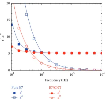
Figure 1: The dielectric spectra of the low-resistivity NLC E7 and high-resistivity NLC CYLC-01 confined in homogeneous cells at 303 K.𝜀 and𝜀 are the real and imaginary parts of the complex dielectric function.
3. Results and Discussion
Figure 1 shows the frequency dependence of the real and imaginary parts of the complex dielectric function(𝜀− 𝑖𝜀) of pure E7 and pure CYLC-01. In the low-frequency region (f < 102Hz), the dielectric behavior was attributable to the space-charge polarization. Both frequency-varying𝜀and𝜀, dominated by the ionic effect in this frequency region, are proportional to𝑓−3/2and𝑓−1, respectively. Taking the diffu-sive motion of the impurity ions into account, the expressions for the ionic contributions to the dielectric dispersion𝜀and dielectric loss𝜀 in the appropriate frequency range in the nematic LC cell are [15]
𝜀(𝑓) = 𝑛𝑞2𝐷3/2 𝜋3/2𝜀 0𝐿𝑘𝐵𝑇𝑓 −3/2+ 𝜀 𝑏, (1) 𝜀(𝑓) = 𝑛𝑞2𝐷 𝜋𝜀0𝑘𝐵𝑇𝑓−1, (2)
respectively, where𝑛 is the mobile ion concentration, q is the charge of an ion, D is the diffusion constant of the ion, L is the thickness of the cells,𝜀0is the permittivity in free space, 𝑘𝐵is the Boltzmann constant, T is the absolute temperature, and 𝜀𝑏 is the intrinsic dielectric constant of the NLC bulk. The ionic contribution decreased with increasing frequency. At low frequencies the impurity ions had enough time to reach the electrodes to form dipole moments, while at high frequencies the space-charge polarization could not keep up with the polarity alteration of the electric field, which, in turn, led to the dielectric relaxation. The constant value of 𝜀 between 103 and 104Hz was mainly contributed by the
intrinsic LC dielectric term𝜀𝑏. It is clear fromFigure 1that the dielectric relaxation in the low-frequency region (10 Hz< f < 100 Hz) was not evident in the dielectric spectrum
0 1 2 3 4 CYLC-01/CNT Frequency (Hz) Pure CYLC-01 𝜀 𝜀 𝜀 𝜀 101 102 103 104 𝜀 ,𝜀
Figure 2: The dielectric spectra of pristine and 0.05 wt% CNT-doped CYLC-01 in homogeneously aligned cells at 303 K.
of the superfluorinated LC mixture CYLC-01. As mentioned above, CYLC-01 was a high-resistivity NLC, connoting that it contained a very limited amount of impurity ions. Conse-quently, the ionic contribution was not as significant at low frequencies compared with the E7 counterpart.
Figure 2depicts the dielectric spectra of pure as well as CNT-doped CYLC-01 samples. Since their real parts almost coincide with each other and imaginary parts are virtually identical, the dopant effect on the dielectric behavior (in the frequency range studied) was trivial in the TFT-grade NLC. In contrast, the impact of the dopant on the low-frequency dielectric spectrum was very pronounced for the E7 host as shown inFigure 3. One can see from this figure that, after doping 0.05-wt% CNTs in E7, the dielectric permittivity (𝜀)
decreased in the low-frequency region and the relaxation frequency shifted to the lower frequency. Again, E7 is a low-resistivity NLC, which contains a large amount of impurity ions. The CNTs as an additive in the ion-rich nematic host effectively trapped mobile ions [5] to give rise to the reduction in space-charge polarization.
The VHR is an important measure of the LCD perfor-mance. It is conventionally defined as
VHR(%) =𝑉𝑡
𝑉𝑖 × 100%, (3)
where 𝑉𝑖 is the initial (or input) pulse voltage (5 V in this study) and𝑉𝑡is the terminal voltage of the LC cell during a frame time of 16.67 ms. One can see fromFigure 4 that, by adding an adequate amount of CNTs in E7, the VHR was promoted from 48% to 61%, yielding a substantial increase by 26%. In order to monitor the degradation of the cell manifested by the decrease in VHR over time, a four-day observation was made.Figure 5illustrates the time-evolved VHR curves for the doped and undoped cells. The monotonic fall of the VHR in both cells can be explained by the ascending
0 5 10 15 20 Frequency (Hz) 101 102 103 104 𝜀 ,𝜀 E7/CNT Pure E7 𝜀 𝜀 𝜀 𝜀
Figure 3: The dielectric spectra of pure and 0.05 wt% CNT-doped E7 in homogeneous cells at 303 K. 0 5 10 15 20 0 1 2 3 4 5 V o lt ag e (V) Time (ms) Pure E7 E7/CNT
Figure 4: Voltage responses of doped and undoped E7 cells to a 5-V square-wave pulse of 15.6𝜇s.
ionic concentration after the cell fabrication [16]. Using the monoexponential decay expression VHR(𝑡) = 𝐴𝑒−𝑡/𝜏, where 𝐴 is the VHR at time 𝑡 = 0 and 𝜏 is the characteristic lifetime, one can fit the experimental data and obtain a lifetime of 118 h for the doped cell compared with that of 59 h for the undoped counterpart. Obviously, the addition of CNTs in E7 prolonged the cell lifetime before degradation.
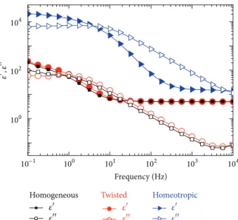
Figure 6shows the dielectric spectra of E7 in various cells with homogeneous, twisted, and homeotropic alignment. In the 103–104Hz frequency region, the dielectric constant𝜀of E7 was the largest in the homeotropic configuration, because
0 24 48 72 96 0 20 40 60 VHR (%) Time (h) Pure E7 E7/CNT
Figure 5: Time-evolved VHR curves in a period of 96 h.
Twisted Homogeneous Frequency (Hz) Homeotropic 101 100 102 103 104 100 102 104 10−1 𝜀 ,𝜀 𝜀 𝜀 𝜀 𝜀 𝜀 𝜀
Figure 6: The dielectric spectra of E7 in homogeneous, twisted, and homeotropic cells at 296 K.
E7 possessed positive dielectric anisotropy. Note that the effective dielectric constant𝜀 can be expressed by [17]
𝜀 = 𝜀⊥+ Δ𝜀 sin2𝜃, (4)
where𝜃 is the tilt angle between the substrate plane and the LC director. Thus, the complex dielectric constant measured in a homeotropic cell is the sole contribution of the parallel component𝜀‖. In the frequency region of𝑓 < 103Hz, both 𝜀 and 𝜀 functions can be individually fitted by (1) and
(2), respectively, for calculation of their ion density𝑛 and diffusion constant𝐷. The results are listed inTable 1.
The impurity ions in the LC bulk can be contributed by the dissociation of the LC material itself and ion injection from the alignment or electrode layer [18, 19]. Based on
Table 1: Ion concentration n and diffusion constant D in E7 for homogeneous, twisted, and homeotropic cells at 296 K.
Cell type n (cm−3) D (cm2s−1)
Homogeneous 1.80× 10¹³ 2.67× 10⁻⁷
Twisted 1.74× 10¹³ 3.55× 10⁻⁷
Homeotropic 5.12× 10¹⁵ 5.72× 10⁻⁷
the data displayed inTable 1, the ion concentration in the homeotropic cells was much (two orders of magnitude) higher than that in the other cells with different configura-tions. Here, the most likely explanation is the occurrence of ion injection into the LC bulk from the homeotropic align-ment layers because the electrodes are identical. The ionic concentrations in the homogeneous and twisted-nematic cells are quite the same due to the use of the same aligning material.
The diffusion constant𝐷 is anisotropic and related to the viscosity and electrical conductivity of the medium [7,11]. Table 1 reveals that 𝐷 in a homeotropic cell was larger in comparison with that in a homogeneous one. This result, arising from the fact that the diffusion constant along the molecular axis is greater (namely, 𝐷‖ > 𝐷⊥), is in good agreement with an earlier study by Costa et al. [11]. We also observed that𝐷 in the twisted cells is somewhat larger than that in the homogeneous cells. Since the viscosity of the LC E7 in splay and twist molecular configurations is identical [20], we believe that the difference can be ignored due to the experimental error and uncertainties in the curve-fitting process. As a result, it can be summarized that the alignment layer and molecular orientation play an important role in ionic concentration and diffusion constant, respectively. The dc conductivity can be written as
𝜎dc= 𝑞𝑛𝜇, (5)
where𝜇 is the ion mobility. According to the Einstein relation 𝜇 = 𝑘𝑞 𝐵𝑇𝐷, (6) (5) becomes 𝜎dc = 𝑛𝑞2𝐷 𝑘𝐵𝑇, (7)
indicating that the ionic dc conductivity 𝜎dc is not only
proportional to the ion concentration n, but also to the diffusion constant𝐷. Thus, the conductivity of an LC cell changes with the variation of𝐷 in different LC alignment.
4. Conclusions
This paper presents the low-frequency (f < 102Hz) dielectric behaviors induced by impurity ions in LC cells under differ-ent conditions. In the high-resistivity NLC (CYLC-01) which contained a low concentration of impurity ions, we did not observe an evident sign of the mobile-ion polarization and the dielectric constant did not seem to change after doping
CNTs. By contrast, the dielectric relaxation was obviously observed in the low-resistivity NLC (E7) rich in impurity ions. Our experimental results suggested that CNTs as a dopant can effectively suppress the ion effect in the low-resistivity NLC, thereby promoting the VHR substantially. In addition, the low-resistivity NLC confined in homeotropic cells, in comparison with cells in the homogeneous and twisted configurations, exhibited the highest impurity-ion concentration, implying significant ion injection from the corresponding alignment layers.
Acknowledgment
The authors are thankful for the financial support of the National Science Council of Taiwan under Grant nos. NSC 98-2112-M-033-004-MY3, NSC 101-2112-M-009-018-MY3, and NSC 101-2811-M-009-059.
References
[1] S. H. Perlmutter, D. Doroski, and G. Moddel, “Degradation of liquid crystal device performance due to selective adsorption of ions,” Applied Physics Letters, vol. 69, no. 9, pp. 1182–1184, 1996. [2] C. Colpaert, B. Maximus, and A. de Meyere, “Adequate measur-ing techniques for ions in liquid crystal layers,” Liquid Crystals, vol. 21, no. 1, pp. 133–142, 1996.
[3] V. A. Tsevetkov and O. V. Tevetkov, “Ions influence on electrooptical characteristics of NLC,” Molecular Crystals and
Liquid Crystals, vol. 368, no. 1, pp. 625–632, 2001.
[4] L. O. Palomares, J. A. Reyes, and G. Barbero, “Optical response of a nematic sample submitted to a periodic external electric field: role of the ionic impurities,” Physics Letters A, vol. 333, no. 1-2, pp. 157–163, 2004.
[5] M. Rahman and W. Lee, “Scientific duo of carbon nanotubes and nematic liquid crystals,” Journal of Physics D, vol. 42, Article ID 063001, 12 pages, 2009.
[6] H. Y. Chen and W. Lee, “Suppression of field screening in nematic liquid crystals by carbon nanotubes,” Applied Physics
Letters, vol. 88, Article ID 222105, 3 pages, 2006.
[7] B. R. Jian, C. Y. Tang, and W. Lee, “Temperature-dependent electrical properties of dilute suspensions of carbon nanotubes in nematic liquid crystals,” Carbon, vol. 49, no. 3, pp. 910–914, 2011.
[8] H. H. Liu and W. Lee, “Ionic properties of liquid crys-tals dispersed with carbon nanotubes and montmorillonite nanoplatelets,” Applied Physics Letters, vol. 97, no. 17, Article ID 173501, 3 pages, 2010.
[9] C. Y. Tang, S. M. Huang, and W. Lee, “Electrical properties of nematic liquid crystals doped with anatase TiO2nanoparticles,”
Journal of Physics D, vol. 44, Article ID 355102, 5 pages, 2011.
[10] S. Murakami and H. Naito, “Electrode and interface polariza-tions in nematic liquid crystal cells,” Japanese Journal of Applied
Physics, vol. 36, no. 4, pp. 2222–2227, 1997.
[11] M. R. Costa, R. A. C. Altafim, and A. P. Mammana, “Ionic impurities in nematic liquid crystal displays,” Liquid Crystals, vol. 28, no. 12, pp. 1779–1783, 2001.
[12] Merck data sheets.
[13] H. Y. Chen, W. Lee, and N. A. Clark, “Faster electro-optical response characteristics of a carbon-nanotubenematic suspen-sion,” Applied Physics Letters, vol. 90, Article ID 033510, 3 pages, 2007.
[14] C. Y. Tang, Y. C. Lin, and W. Lee, “Voltage holding ratio of a nematic liquid crystal cell under UV exposure,” in Proceedings of
the Photonics Global Conference, Suntec Singapore International
Convention & Exhibition Centre, Singapore, December 2010. [15] G. Barbero and A. L. Alexe-Ionescu, “Role of the diffuse layer
of the ionic charge on the impedance spectroscopy of a cell of liquid,” Liquid Crystals, vol. 32, no. 7, pp. 943–949, 2005. [16] H. H. Liu and W. Lee, “Time-varying ionic properties of a
liquid-crystal cell,” Applied Physics Letters, vol. 97, Article ID 023510, 3 pages, 2010.
[17] W. Lee, J. S. Gau, and H. Y. Chen, “Electro-optical properties of planar nematic cells impregnated with carbon nanosolids,”
Applied Physics B, vol. 81, no. 2-3, pp. 171–175, 2005.
[18] S. Murakami and H. Naito, “Charge injection and generation in nematic liquid crystal cells,” Japanese Journal of Applied Physics, vol. 36, no. 2, pp. 773–776, 1997.
[19] H. de Vleeschouwer, A. Verschueren, F. Bougrioua et al., “Dispersive ion generation in nematic liquid crystal displays,”
Japanese Journal of Applied Physics A, vol. 41, no. 3, pp. 1489–
1494, 2002.
[20] H. J. Coles and M. S. Bancroft, “Viscosity coefficients and elastic constants of nematic solutions of a side-chain polymer,”
Molecular Crystals and Liquid Crystals Science and Technology. Section A, vol. 237, no. 1, pp. 97–110, 1993.
Submit your manuscripts at
http://www.hindawi.com
Hindawi Publishing Corporation
http://www.hindawi.com Volume 2014
High Energy PhysicsAdvances in
World Journal
Hindawi Publishing Corporation
http://www.hindawi.com Volume 2014
Hindawi Publishing Corporation
http://www.hindawi.com Volume 2014
Fluids
Journal ofAtomic and Molecular Physics
Journal of
Hindawi Publishing Corporation
http://www.hindawi.com Volume 2014
Hindawi Publishing Corporation
http://www.hindawi.com Volume 2014
Condensed Matter Physics
Optics
International Journal of
Hindawi Publishing Corporation
http://www.hindawi.com Volume 2014
Hindawi Publishing Corporation
http://www.hindawi.com Volume 2014
Advances in
Astronomy
International Journal of
Hindawi Publishing Corporation
http://www.hindawi.com Volume 2014
Superconductivity
Hindawi Publishing Corporation
http://www.hindawi.com Volume 2014
Statistical Mechanics International Journal of
Hindawi Publishing Corporation
http://www.hindawi.com Volume 2014
Gravity
Hindawi Publishing Corporation
http://www.hindawi.com Volume 2014
Astrophysics
Journal ofHindawi Publishing Corporation
http://www.hindawi.com Volume 2014
Physics
Research International
Hindawi Publishing Corporation
http://www.hindawi.com Volume 2014
Solid State PhysicsJournal of Computational Methods in Physics
Journal of
Hindawi Publishing Corporation
http://www.hindawi.com Volume 2014
Hindawi Publishing Corporation
http://www.hindawi.com Volume 2014
Soft Matter
Hindawi Publishing Corporation http://www.hindawi.com
Aerodynamics
Journal ofVolume 2014
Hindawi Publishing Corporation
http://www.hindawi.com Volume 2014
Photonics
Hindawi Publishing Corporation
http://www.hindawi.com Volume 2014 Journal of
Biophysics
Hindawi Publishing Corporation
http://www.hindawi.com Volume 2014