Highly efficient white organic electroluminescent devices based on tandem
architecture
Chan-Ching Chang, Jenn-Fang Chen, Shiao-Wen Hwang, and Chin H. Chen
Citation: Applied Physics Letters 87, 253501 (2005); doi: 10.1063/1.2147730
View online: http://dx.doi.org/10.1063/1.2147730
View Table of Contents: http://scitation.aip.org/content/aip/journal/apl/87/25?ver=pdfcov Published by the AIP Publishing
Articles you may be interested in
Highly efficient, single-layer organic light-emitting devices based on a graded-composition emissive layer Appl. Phys. Lett. 97, 083308 (2010); 10.1063/1.3481426
Color-stable, efficient fluorescent pure-white organic light-emitting diodes with device architecture preventing excessive exciton formation on guest
Appl. Phys. Lett. 92, 223504 (2008); 10.1063/1.2926423
Star-configured carbazole as an efficient near-ultraviolet emitter and hole-transporting material for organic light-emitting devices
Appl. Phys. Lett. 92, 073305 (2008); 10.1063/1.2841063
Highly efficient top-emitting white organic electroluminescent devices Appl. Phys. Lett. 86, 253508 (2005); 10.1063/1.1953883
Highly efficient red electrophosphorescent devices based on an iridium complex with trifluoromethyl-substituted pyrimidine ligand
Appl. Phys. Lett. 85, 1619 (2004); 10.1063/1.1786369
This article is copyrighted as indicated in the article. Reuse of AIP content is subject to the terms at: http://scitation.aip.org/termsconditions. Downloaded to IP: 140.113.38.11 On: Wed, 30 Apr 2014 06:58:45
Highly efficient white organic electroluminescent devices based
on tandem architecture
Chan-Ching Changa兲 and Jenn-Fang Chen
Department of Electrophysics, National Chiao Tung University, Taiwan, Republic of China
Shiao-Wen Hwangb兲and Chin H. Chen
Display Institute, MIRC, National Chiao Tung University, Taiwan, Republic of China
共Received 6 July 2005; accepted 9 November 2005; published online 12 December 2005兲 Two types of tandem organic light-emitting diodes共OLEDs兲 with white-light emission have been developed by using Mg: Alq3/ WO3 as the interconnecting layer. While the Commission Internationale d’Eclairage 共CIE兲 coordinates of the tandem device with individual blue- and yellow-emitting OLEDs was sensitive to the viewing angle and the operating time, the tandem device connecting two white-emitting OLEDs was considerably less. At an optimal WO3thickness
of 5 nm, the tandem two-unit device produced three higher luminance efficiency than that expected of a single-unit device. A maximum efficiency of 22 cd/ A was achieved by the tandem device comprised of two white-fluorescent OLEDs, and the projected half-life under the initial luminance of 100 cd/ m2was over 80 000 h. © 2005 American Institute of Physics.关DOI:10.1063/1.2147730兴
Organic light-emitting devices have attracted a great deal of attention as they possess attributes that are superior to many of today’s mainstream displays and illumination sources. They can emit various colors by using a wide selec-tion of organic fluorescent or phosphorescent dyes. Various green, blue, and red organic light-emitting diodes共OLEDs兲 with high luminance efficiency, low-power consumption, and long operational life have been demonstrated, and their com-mercialization is well underway. Recently, white OLEDs 共WOLEDs兲 have also attracted considerable attention due to their applications in the “maskless” fabrication process of large-area full color displays by coupling with color filters, or simply by using them as backlight for liquid crystal dis-plays and paper-thin light sources. For large-scale applica-tions, WOLEDs are a high-quality, low-cost, thin-film, flex-ible option, superior to inorganic light-emitting diodes 共LEDs兲 or fluorescent lamps.
White-light emission requires the mixing of two comple-mentary colors or three primary colors. Various device struc-tures and research for generating white light have been reported.1–3 Doping the light-emitting layers with various fluorescent or phosphorescent dyes has been widely used since the first demonstration by Tang and co-workers at Kodak. Careful control of the location of exciton-recombination zone and/or the energy-transfer between the host and dopant molecules is needed to obtain a balanced white emission.4,5Although at the present, the phosphores-cent OLEDs have been demonstrated to achieve white emis-sion with high efficiency, the operating reliability still re-quires further research.6 Recently, another elegant solution was provided by Matsumoto et al.7 who, in IDMC’03, re-ported a stacked OLED by connecting individual blue and red devices in series to achieve pink emission with CIEx,yof 0.36, 0.23. It is expected that various hues can be obtained by this kind of tandem device without worrying about the potential shift of the recombination zone, which leads to
un-desired emission color. Furthermore, Kido found that the lu-minance efficiency of the tandem device with N units is usu-ally N times as high as that of the single-unit device. This stratagem seems to be attractive for getting highly efficient WOLEDs. However, few articles discuss the influence of design principle on the devices’ performance and stability.
In this work, two types of tandem WOLEDs containing an interconnecting layer of Mg: Alq3/ WO3, have been fabri-cated and investigated in detail. Mg: Alq3/ WO3 thin film
which has low absorption in the visible region.8It is suitable to be the interconnecting layer for WOLEDs. The architec-tures of the two kinds of tandem WOLEDs are shown in Fig. 1 in which the white emission was obtained by mixing complementary blue and yellow colors. Device 1 was ob-tained by connecting blue and yellow devices in series, while Device 2 stacked two white-emitting devices with the same blue and yellow dopants as used in Device 1. The objective of this research is to obtain a tandem WOLED with high
a兲Author to whom correspondence should be addressed; electronic mail:
b兲Electronic mail: [email protected] FIG. 1. Schematic architectures of the devices and the structures of thedopants.
APPLIED PHYSICS LETTERS 87, 253501共2005兲
0003-6951/2005/87共25兲/253501/3/$22.50 87, 253501-1 © 2005 American Institute of Physics
This article is copyrighted as indicated in the article. Reuse of AIP content is subject to the terms at: http://scitation.aip.org/termsconditions. Downloaded to IP: 140.113.38.11 On: Wed, 30 Apr 2014 06:58:45
efficiency and broadband emission, and to gain some insight in understanding the relationship between the device struc-ture and characteristics, which is expected to aid the fustruc-ture design and fabrication of tandem WOLEDs.
The substrates used in the present experiments were in-dium tin oxide 共ITO兲-coated glass, and the thickness and sheet resistance of the ITO layer were 75 nm and 35⍀/sq, respectively. Prior to deposition of organic compounds, the substrates were treated with oxygen plasma of 200 W for 30 s. Then organic materials were deposited by thermal evaporation in an ULVAC SOLCIET coater at a base vacuum of 10−7Torr. The OLED architectures of the control and two tandem devices are shown schematically in Fig. 1 for comparison, in which the fluorescent dopants for blue and yellow are p-bis共p-N,N-di-phenyl-aminostyryl兲benzene and 5,6,11,12-tetraphenylnaphthacene 共rubrene兲, respectively. The Mg: Alq3layer was co-evaporated from separate heating sources at the same rate of 1 Å / s. All devices were hermeti-cally sealed under nitrogen prior to testing in ambient. The active area of the electroluminescence共EL兲 device, defined by the overlap of the ITO and the cathode electrodes, was 3⫻3 mm2. The current density 共J兲-voltage 共V兲-luminance
characteristics of the devices were measured with a Photo Research PR650 spectrophotometer and a computer-controlled programmable dc source共Keithley 2400兲. The sta-bility tests of these devices were carried out under a nitrogen atmosphere.
White emission is observed from these devices when operated in a continuous dc bias with ITO at positive polar-ity. Figure 2 shows the EL spectra of these three devices at various viewing angles. The EL spectrum of the control WOLED, which covers a wide range of the visible region with three peaks at 470, 500, and 550 nm corresponding to the emissions from DSA-Ph and rubrene, respectively,9stays essentially the same at different viewing angles. On the
con-trary, the relative intensities of peaks at 500 and 550 nm in tandem devices decreased by increasing the viewing angle. This phenomenon is not expected to result from shifting of the recombination zone because these devices were all driven at a fixed current. We attribute the spectrum change to the optical interference or weak microcavity effect in multilayer devices, which has been reported in stacked OLEDs.10 Fur-thermore, the EL spectrum of Device 1 revealed a more acute change with the viewing angle than that of Device 2. This may be due to the fact that the blue and yellow units in Device 1 differed considerably in optical length and emissive position.11Emission with long wavelength is easy to escape from the normal direction. We conclude that by stacking two white-emitting OLEDs, it is possible to obtain a high-efficiency tandem white device with acceptable angular de-pendency characteristics.
Figure 3 shows the normalized EL intensity versus the viewing angle characteristics of the control and tandem de-vices. It is apparent that the emissive intensity of the tandem devices is more sensitive to the viewing angle than that of the control device. The tandem devices revealed the emissive profiles are approximately the same as the Lambertian emit-ter. The inset of Fig. 3 shows the relationship between the
FIG. 4. The luminance efficiency vs current density characteristics of the control and tandem devices made in the same lot. Inset: J-V diagrams of the control and tandem devices.
FIG. 2. Normalized EL spectra of the control and tandem devices at various viewing angles.
FIG. 3. Normalized EL intensity vs viewing angle. Inset: 1931 CIEx,y
coor-dinates vs viewing angle. All data were measured at 20 mA/ cm2.
253501-2 Chang et al. Appl. Phys. Lett. 87, 253501共2005兲
This article is copyrighted as indicated in the article. Reuse of AIP content is subject to the terms at: http://scitation.aip.org/termsconditions. Downloaded to IP: 140.113.38.11 On: Wed, 30 Apr 2014 06:58:45
CIEx,ycoordinates of the emission of these WOLEDs and the viewing angle. The shifts in CIE x and y coordinates of the control device from the viewing angle of 0° to 75° are 0.021 and 0.012, respectively. Compared to the control device, the CIEx,y coordinate shifts of Device 2 increase only slightly
when the viewing angle is larger than 30°. However, it is apparent that the color of Device 1 with shifts of CIE x and
y coordinates of 0.082 and 0.158, is more sensitive to the
viewing angle than that of Device 2. According to our obser-vation of the angular dependence of intensity and color, the microcavity effect is present in these tandem devices.
Figure 4 shows the luminance efficiency versus lumi-nance characteristics of these WOLEDs, which were mea-sured normal to the device surface. The maximum luminance of tandem devices reaches beyond 60 000 cd/ m2. The J-V characteristics of the control and the tandem devices are shown in the inset of Fig. 4. As expected, the driving voltage increases with the increasing number of active units. The driving voltages共at 20 mA/cm2兲 of the control, and Devices
1 and 2 are 7.8 V, 19.1 V, and 16.9 V, respectively. Device 2 exhibited the highest efficiency of 22 cd/ A, which was almost three times that of the control device. Under different levels of brightness, i.e., various current densities, no current induced quench and CIE coordinate shift were observed in the control device and Device 2. This signifies that the re-combination zone was near the interface of the blue- and yellow-emitting layer, and there was no significant shift of the emissive zone in the devices.12 Therefore, Device 2 ap-peared to display the nature of its constitutor, i.e., the control device. An interesting amplification effect was also observed in Device 2, in which three times the efficiency of the control WOLED could be achieved by just connecting two devices. This presumably is due to the microcavity effect which en-hances the amount of light emitted in the forward direction as shown in Fig. 3. In our previous study, a two-unit green device had been observed to produce four times the amplification.13 Therefore, it is important to have a good optical design for producing better light extraction from the device.
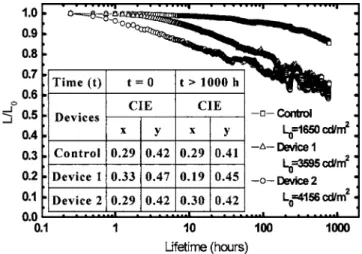
The operational stability of these devices, tested under the condition of constant current density of 20 mA/ cm2, is shown in Fig. 5. Different decay trends were observed in the three devices. Device 2 was the least stable, while the control device showed the longest half-life共t1/2兲. This may be due to the fact that Device 2 suffered more driving power 共J⫻V = 0.382 W / cm2兲 than the control 共0.156 W/cm2兲 and Device 1 共0.338 W/cm2兲. Thermal breakdown processes may be present in these tandem devices due to the nonohmic contact of the interconnecting layer.14 However, assuming the scal-able law of Coulombic degradation for driving at L0 of 100 cd/ m2, the half-life共t
1/2兲 of Device 2 is projected to be
greater than 80 000 h. The inset of Fig. 5 also shows the CIE coordinates of the control device versus Devices 1 and 2. It is evident that the color of Device 2 almost remained the same after 1000 h while that of Device 1 due to the different decay rate of blue and yellow devices changed dramatically.
In summary, two tandem organic white-emitting diodes have been developed by using Mg: Alq3/ WO3 as the
inter-connecting layer. In these tandem devices, the emissive in-tensity and color are dependent on the viewing angle. The microcavity effect may be one of the dominant reasons for the angular dependence effect. So, it is important to have a good optical design for the tandem device. However, the tandem device made by stacking two white-emitting OLEDs could produce devices with high efficiency, good color reli-ability, and sufficient operating stability. The stratagem seems favorable for obtaining a white tandem device with an efficiency as high as 22 cd/ A and acceptable angular depen-dency characteristics.
This work was supported by the MOE Program for Pro-moting Academic Excellence of Universities under Grant No. 91-E-FA04-2-4-B. The research grant of Industry/ Academia Cooperation Project provided by Chunghwa Pic-ture Tubes Ltd. is gratefully acknowledged.
1J. Kido, in Organic Electroluminescent Materials and Devices, edited by
S. Miyata and H. S. Nalwa 共Gordon and Breach, Amsterdam, 1997兲, p. 335.
2A. Dodabalapur, L. J. Rothberg, and T. M. Miller, Appl. Phys. Lett. 65,
2308共1994兲.
3R. S. Deshpande, V. Bulovic, and S. R. Forrest, Appl. Phys. Lett. 75, 888
共1999兲.
4C. H. Kim and J. Shinar, Appl. Phys. Lett. 80, 2201共2002兲.
5J. T. Lim, N. H. Lee, Y. J. Ahn, G. W. Kang, and C. H. Lee, Curr. Appl.
Phys. 2, 295共2002兲.
6B. W. D’Andrade, B. J. Holmesc, and S. R. Forrest, Adv. Mater.
共Wein-heim, Ger.兲 16, 624 共2004兲.
7T. Matsumoto, T. Nakada, J. Endo, K. Mori, N. Kawamura, A. Yokoi, and
J. Kido, in Proceedings IDMC’03共2003兲, p. 413.
8C. C. Chang, S. W. Hwang, C. H. Chen, and J. F. Chen, in Proceedings of
the IDW’04共2004兲, 1285.
9M. T. Lee, H. H. Chen, C. H. Liao, C. H. Tsai, and C. H. Chen, Appl.
Phys. Lett. 85, 3301共2004兲.
10V. Bulovic, V. B. Khalfin, G. Gu, P. E. Burrows, D. Z. Garbuzov, and S. R.
Forrest, Phys. Rev. B 58, 3730共1998兲.
11A. Dodabalapur, L. J. Rothberg, R. H. Jordan, T. M. Miller, R. E. Slusher,
and J. M. Phillipse, J. Appl. Phys. 80, 6955共1996兲.
12T. H. Liu, Y. S. Wu, M. T. Lee, H. H. Chen, C. H. Liao, and C. H. Chen,
Appl. Phys. Lett. 85, 19共2004兲.
13C. C. Chang, S. W. Hwang, C. H. Chen, and J. F. Chen, Jpn. J. Appl.
Phys., Part 1 43, 6418共2004兲.
14X. Zhou, J. He, L. S. Liao, M. Lu, X. M. Ding, X. Y. Hou, X. M. Zhang,
X. Q. He, and S. T. Lee, Adv. Mater.共Weinheim, Ger.兲 12, 265 共2000兲. FIG. 5. Comparison of the operational stability of the control and tandem
devices at 20 mA/ cm2. Inset table: The CIE
x,ycoordinates of the control and
tandem devices at initial and after testing for 1000 h.
253501-3 Chang et al. Appl. Phys. Lett. 87, 253501共2005兲
This article is copyrighted as indicated in the article. Reuse of AIP content is subject to the terms at: http://scitation.aip.org/termsconditions. Downloaded to IP: 140.113.38.11 On: Wed, 30 Apr 2014 06:58:45