行政院國家科學委員會專題研究計畫 成果報告
鈑金材料異向性及可成形性之理論研究與應用
研究成果報告(精簡版)
計 畫 類 別 : 個別型
計 畫 編 號 : NSC 96-2221-E-151-042-
執 行 期 間 : 96 年 08 月 01 日至 97 年 07 月 31 日
執 行 單 位 : 國立高雄應用科技大學模具工程系
計 畫 主 持 人 : 許進忠
計畫參與人員: 碩士班研究生-兼任助理人員:張國緯
碩士班研究生-兼任助理人員:黃銘毅
碩士班研究生-兼任助理人員:方聖豪
碩士班研究生-兼任助理人員:張書樺
報 告 附 件 : 出席國際會議研究心得報告及發表論文
處 理 方 式 : 本計畫涉及專利或其他智慧財產權,2 年後可公開查詢
中 華 民 國 97 年 08 月 29 日
行政院國家科學委員會補助專題研究計畫
□ 成 果 報 告
▓期中進度報告
鈑金材料異向性及可成形性之理論研究與應用(1/3)
計畫類別:▓ 個別型計畫
□ 整合型計畫
計畫編號:NSC
96-2221-E-151 -042
執行期間:
96 年 8 月 01 日至 97 年 7 月 31 日
計畫主持人:
許進忠
共同主持人:
計畫參與人員:
張國緯、黃銘毅、方聖豪、張書樺
成果報告類型(依經費核定清單規定繳交):▓精簡報告
□完整報告
本成果報告包括以下應繳交之附件:
□赴國外出差或研習心得報告一份
□赴大陸地區出差或研習心得報告一份
▓出席國際學術會議心得報告及發表之論文各一份
□國際合作研究計畫國外研究報告書一份
處理方式:除產學合作研究計畫、提升產業技術及人才培育研究計畫、
列管計畫及下列情形者外,得立即公開查詢
□涉及專利或其他智慧財產權,□一年▓二年後可公開查詢
執行單位:
國立高雄應用科技大學
中
華
民
國
97 年
7 月
31
日
摘要
本計畫預計以三年時間有系統進行鈑金成形基礎理論與應用推廣研究,主
要目的在擴展基礎理論研究,並應用於工業界中之碟型天線精密模具設計,第
一年完成考慮彈性變形之鈑金材料異向性與應變為基之成形性理論推導,設計
考慮彈性變形之異向性拉伸實驗與量測方法。將考慮彈性變形後之平面異向性
導入應變能量法,以進行應變場及彈回分析,再輔以有限元素法進行詳細分
析,獲取更完整分析資料,最後以單曲率半球形引伸實驗證明考慮彈性變形之
異向性參數之實用性。以精密四軸座標量測設備量測試片幾何來驗證分析理
論,並發展影像處理程式,以非接觸方式量測試片之變形尺寸。本研究與前人
之主要差別於整合彈性變形、異向性、破壞等理論與應變能量理論,而非個別
考慮探討。
關鍵字: 異向性、破壞理論、應變能量法、影像處理技術、彈回分析、有限
元素法
ABSTRACT
This is a three-year project aiming at the development of basic anisotropic and
fracturing theories, and the applications. The developed theories will be applied to
the precision die design of industrial products, such as the disk antenna. In the first
year, the research work is focused on the development of the anisotropy and the
fracture criterion. The tensile and single curvature semi-sphere drawing tests will
be designed and carried out to determine the parameters of anisotropy and fracture
criterion with the consideration of elastic deformation. The planar anisotropy
model will be integrated into the axisymmetrical strain energy method. The
forming process and the springback effect will be analyzed. A FEM program will
be adopted to do the detail analysis and compare with the results of strain energy
method. The experimental results will be measured via a precision four-axis CMM
to evaluate the theoretical models and analysis results. An image processing
program will be developed to measure the major dimensions of the tested
s
pe
c
i
me
ns
.
Thi
s
r
e
s
e
a
r
c
h
di
f
f
e
r
s
wi
t
h
t
he
ot
he
r
r
e
s
e
a
r
c
he
r
s
’
wor
ks
ma
i
nl
y
a
t
t
he
integration of the elastic deformation, anisotropy, fracture criterion and the strain
energy theories.
KEYWORDS:
anisotropy, fracture criterion, strain energy method, image
processing technology, FEM
1. 前言
在金屬鈑金成形中,影響衝壓成形結果的因子有許多,且有鑑於材料科學上持續的進
步、在要求大量生產精度高且均一的產品時,便包含有許多難解的問題。金屬鈑金於深引
伸成形時,由於受到鈑料本身異向性之影響,鈑料各個角度所引發的應變變形量也會不同,
進而造成成品邊緣高度起伏變化,此現象亦被稱為凸耳或耳緣現象;由於受限於材料製造
的技術,材料內部的異向性難以去除,因此在金屬材料異向性之研究上,許多國內外學者
一直以各種方法理論進行深入探討。2001 年 Xue 等人
[1,2]
以能量法預測軸對稱及非相等雙
曲率成形之彈回,以薄膜原理及薄殼旋轉及能量法考慮彎曲與彎曲缷彎過程,以半球形模
具及沖頭近似分析在中立面上圓周方向分佈之薄膜應變,以塑性變形理論表示應力及應變
關係,導出薄膜之整體應變能量,以最佳化方法求出最小變形能量場,在彈回時,將彈性
變形項去除,加上彈性變形虎克定律建立相對應力,在滿足幾何相適性下,可算出彈回後
幾何。Hu 等人
[3]
將 Barlat-Lian 異向性準則以彈塑性變形及一種分離的 Kirchhoff 三角網格
模型,導入 quasi-flow corner theory,並配合有限元素分析,發現深引伸成形時,異向性對
於凸耳有相當的影響,如凸耳的大小、數目、位置等,但是材料加工硬化指數只與凸耳的
大小有關,而不與凸耳的數目和方向有關。2002 年 Hu 等人
[4]
把異向性當作一個重要因素,
並探討各種不同之鈑金成形之影響,並根據 Hill 理論,將等效應變轉以異向性為函數之表
示,有效的分辨出異向性對於不同鈑金成形的影響。2005 年 Chamanfar 等人
[5]
根據 J.
Danckert 的理論,考慮體積改變之影響,建立更接近實際的異向性 r 值定義法。2006 年
Yoon
[6]
提出一種新的材料之異向性準則,發現所提出之鋁鈑材料經圓杯分析後會有 8 個凸
耳的發生,比起傳統的 Lankford parameters model 更為切確。2007 年 Engler 等人
[7]
提出以
不同鋁合金鈑材經圓杯引伸後,因為材料內部塑性多晶體的不同,而會有多種的凸耳現象
產生,如 2 凸耳、4 凸耳及 8 個凸耳等,發現塑性多晶體的位置、大小是攸關凸耳產生的
數目及位置。2008 年 Agrawal 等人
[8]
提出應用 upper bound method 將正規化後的異向性 R
值導入,進而有效最佳胚料,降低引伸後的凸耳發生。
表 1 目前計畫研究成果之載具說明
成品幾何特徵
理論推導
剖面(子午
線)輪廓
圓周輪
廓外形
異向性理論
R 值量測方式
能量法
驗證載具(成品)
無凸緣,單
曲率
圓形
單 一 平 均 異 向 性
(三個角度平均值)
軸對稱模式, R
值為單一常數
無凸緣,雙
曲率(在零
度 及 九 十
度斷面)
橢圓
單 一 平 均 異 向 性
(R 值), 使用拉伸
實驗量測 R 值,影
像處理驗證 R 值。
非 軸 對 稱 模 式
(雙曲率橢圓二
次曲面),R 值
為單一常數
圖 1 圓杯杯高與材料異向性因子示意圖
第一年計畫研究工作是於應變能量法中導入材料平均異向性因子,並去進行成形應變預
測、以及彈回分析與控制等部分;為驗證本研究所提出之方法之可行性及正確性,本計劃
以單曲率及雙曲率曲面衝壓成形為例(表 1),驗證成形應變預測、及彈回分析之結果;而在
影像處理程式的開發,將設計並完成無凸緣圓杯(
圖 1
)引伸實驗與杯緣尺寸非接觸方式量影
像自動量測方法,並與有限元素分析結果比較,以探討異向性(R 值)與杯高關係。
材料性質試驗結果
本研究選用中鋼生產之 SPCC-CQ#2 成形加工用軟鋼進行 FEM 成形分析,將其鈑料進行拉
伸試驗並求得材料參數,其實驗所得之材料參數如下表 2 所示:
表 2 SPCC-CQ#2 材料性質表
Material
SPCC-CQ#2
Mass Density
7.85E-9
Ton/mm3
Young’
s
Modul
us
2.16E+5
MPa
Poi
s
s
on’
s
Ra
t
i
o
0.28
Yield Stress
158.033
MPa
k, coefficient of strength(MPa)
4.723E+2
MPa
n, strain hardening exponent
0.195
Normal Anisotropic Parameter, R
1.699
電腦輔助成形分析系統
為快速得到雙曲率曲面衝壓成形之胚料展開設計尺寸,及定義分析曲面元素,以便利用數
值最佳化求解應變最佳化函數,預測成形應變場,本研究以物件導向之程式編輯軟體
(Borland C++ Builder)建立電腦輔助成形分析系統,如
圖 2
所示:
R
00R
45R
90圖 2 電腦輔助成形分析系統
此系統包含以下三大模組:
1. 胚料展開與設計模組、2. 成形應變能量分析模組、3. 彈回分析模組
曲面衝壓成形實驗
本研究選用中鋼生產之 SPCC-CQ#2 成形加工用軟鋼進行 FEM 成形分析及成形實驗,其材
料參數如下表 2 及所示;為探討成品兩方向曲率半徑對成形性之影響,本研究於兩方向採
用不同之曲率半徑,其比值為 1.5,成形深度為 5mm,
圖 3 及圖 4
為本研究衝壓成形實驗
用模具圖。
圖 3 曲面衝壓成形模具示意圖
(a)R
x方向
(b)R
y方向
圖 4 曲面衝壓成形模具
並利用 50 頓萬能材料試驗機進行曲面衝壓成形實驗。為正確量測曲面成形後之曲率變化,
本研究利用精密四軸座標量測量床 (
圖 5
)進行量測工作,其量測結果可透過電腦控制器擷
取並輸出相關資料,以利與後續分析結果做比較。
圖 5 精密四軸座標量測量床
單曲率曲面成形分析與彈回分析結果
於初期的研究中,為確定分析程式的正確性,先以單曲率對稱半圓球形成品進行成形分析,
並與有限元素及實際成形結果進行比較。其中,胚料厚度為 1 mm,成品曲率半徑為 200 mn,
成形深度為 5 mm;分析參數如表 2 所示。
(b)
控制器
工件夾頭
測頭
(a)開模狀態
(b)閉模狀態
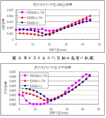
圖 6 與圖 7
分別為單曲率曲面成形軸向應變及成形應變比較圖,在不同異向性情況下,能
量法預測結果與有限元素法相似,代表能量法分析之結果是可信的;其中,當 R 值越大時,
成形軸向應變越大,但在將應變等效後,其影響則不明顯。
單曲率曲面成型-X軸向應變 0 0.001 0.002 0.003 0.004 0.005 0 10 20 30 40 50 X軸位置(mm) X 軸 應 變 FEM(R=1.79) EM(R=1.79) EM(R=1)圖 6 單曲率曲面成形 X 軸向應變比較圖
單曲率曲面成型-等效應變 0.000 0.001 0.002 0.003 0.004 0.005 0.006 0.007 0 10 20 30 40 50 X軸位置(mm) 等 效 應 變 FEM(R=1.79) EM(R=1.79) EM(R=1.)圖 7 單曲率曲面成形等效應變比較圖
單曲率曲面彈回結果比較如
圖 8
所示,能量法所預測的結果與有限元素分析及實驗結果十
分近似,表示本文所提出之方法是可行的。而在考慮異向性的情況下,其結果與不考慮異
向性的結果差異不大,表示異向性在此案例中之影響並不大。
單曲率曲面彈回後分析結果 0 1 2 3 4 5 6 0 10 20 30 40 50 X軸位置(mm) Z 軸 深 度 (m m ) FEM(R=1.79) EM(R=1.79) EM(R=1) Product's Profile Experiment圖 8 單曲率曲面彈回後分析結果比較圖
雙曲率曲面成形分析結果
利用成形應變分析系統,分析厚度為 1 mm 之胚料,成形為雙軸曲率半徑比為 1.5,成品深
度 5 mm 之雙曲率曲面之成形應變場,分析參數如表 2 所述。
圖 9 及圖 10
分別為 X、Y 兩軸上之軸向應變比較圖;如圖所示,能量法所預測之應變趨
勢與有限元素分析結果十分近似,但在 X 軸之成品中心部分,有較大的誤差產生;由於在
第一年計畫中僅考慮平均異向性,且雙曲率曲面成形為三維成形,因此,必須考慮各方向
之異向性才可以有更精確之結果。
X軸向應變(0°) 0 0.001 0.002 0.003 0.004 0.005 0.006 0 10 20 30 40 X軸位置(mm) X 軸 向 應 變 EM(with R) EM(without R) FEM
圖 9 X 軸向應變比較圖
Y軸向應變(90°) 0 0.002 0.004 0.006 0.008 0.01 0 5 10 15 20 25 30 35 Y軸位置(mm) Y 軸 向 應 變 EM(with R) EM(without R) FEM圖 10 Y 軸向應變比較圖
雙曲率曲面成形彈回分析結果
將能量法彈回分析之結果與 FEM 分析之結果進行比較,如圖 11 及圖 12 所示,本文針對
能量法與有限元素法預測之結果,以均方根誤差進行評估,其結果如表 3 所示,此結果顯
示異向性對彈回之影響並不顯著。
表 3 最大均方根誤差比較表
X 軸向均方根誤差(mm)
Y 軸向均方根誤差(mm)
考慮材料異向性
0.226
0.115
不考慮材料異向性
0.206
0.104
沿X軸之彈回分析比較圖( 0°) 0 1 2 3 4 5 6 0 5 10 15 20 25 30 35 40 X軸位置(mm) Z 軸 深 度 (m m ) EM(with R) EM(without R) FEM Product's profile圖 11 沿 X 軸之彈回分析比較圖
沿Y軸之彈回分析比較圖(90°) 0 1 2 3 4 5 6 0 5 10 15 20 25 30 35 Y軸位置(mm) Z 軸 深 度 (m m ) EM(with R) EM(without R) FEM Product's profile
圖 12 沿 Y 軸之彈回分析比較圖
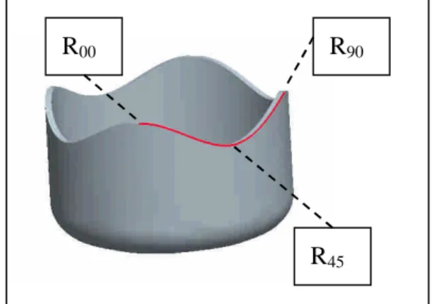
影像處理量測結果(以無凸緣圓杯為例,進行異向性位置判斷)
影像處理量測
在進行實際成形實驗後,為方便量測,並與鈑金成形 CAE 分析軟體模擬軟體之分析結果進
行比較,本研究利用 Matrox Imaging Library (MIL)
TM及 Visual Basic
TM等軟體建構所需之影
像量測系統(
圖 13
),以利進行鈑金成形品量測與異向性位置檢測。其中包括影像擷取、前
處理、校正與量測、異向性位置定位等功能,處理前後之影像分別於底部顯示區直接顯示;
圖 14
為其運作流程圖;
影像自動量測與異向性位置判斷
本研究利用凸耳特性,透過引伸件成形後之外形尺寸比較,以判斷其異向性位置,並歸納
出以下三個異向性影像搜尋法則:
1. 確定最大外形尺寸位置,此位置為 90°方向。
2. 確定最小外形尺寸位置,此位置為 45°方向。
3. 確定 45°-90°區域之外的最大外形尺寸位置,此位置即為 0°方向。
利用邊緣強化之前處理功能,可加強來源影像之成品輪廓,以利後續量測,透過上述異向
性影像搜尋法則,本程式可自動蒐尋胚料上,相對於軋延方向 0°、45°與 90°之位置,並進
行量測及繪出成品輪廓;
圖 15
為程式自動判斷之成品輪廓與異向性位置,本研究利用兩
CCD 取像 等化處理 二值化 Sobel 邊界強化 尺寸校正 尺寸量測 輪廓檢測 結果輸出圖 14 影像量測系統流
圖 13 影像處理程式
不同擷取角度之影像進行比較,其各方向之相對量測誤差均小於 3%(表 4);在 0°方向上有
最大誤差 2.17%,這是由於
圖 15
(A)中 0°方向位於成品之邊緣,造成不易量測正確點所致,
因此,這些誤差是可被接受的。
(A)
(B)
圖 15 成品輪廓蒐尋與異向性位置檢測
表 4 各方向之自動量測結果
Directions
Zero-degree
45-degree
90-degree
View Angle A
22.152
21.726
23.643
View Angle B
22.644
21.828
23.460
Relative error
2.17%
0.46%
-0.77%
References
[1] Xue, P. and Yu, T.X. and Chu, E.: An energy approach for predicting springback of metal sheets after double-curvature forming, Part I : axisymmetric stamping, Int. J. of Mech. Sci. 43 (2001)
pp.1893-1914.
[2] Xue, P. and Yu, T.X. and Chu, E.: An energy approach for predicting springback of metal sheets after double-curvature forming, Part II : Unequal double-curvature forming, Int. J. of Mech. Sci. 43 (2001) pp.1915-1924.
[3] Hu, P. and Liu, Y.Q. and Wang, J.C.: Numerical study of the flange earring of deep-drawing, Int. J. of Mech. Sci. 43 (2001) pp.279-296.
[4] Hu, W. and Wang, Z.R.: Anisotropic characteristics of materials and basic selecting rules with different sheet metal forming processes, J. Mater. Proc. Technol., Vol. 127, (2002), 374-381.
[5] Chamanfar, A. and Mahmudi, R.: Compensation of elastic strains in the determination of plastic strain ratio (R) in sheet metals, Material Sciences & Engineering A, Vol.397( 2005), pp.153-156
--- R90 --- R45 --- R 0 --- R90 --- R45 --- R 0
Functions, J. Mater. Proc. Technol., Vol. 177, (2006), 134-137.
[7] Engler, O. and Hirsch, J.: Polycrystal-plasticity simulation of six and eight ears in deep-drawn aluminum cups, Materials Science and Engineering A 452–453 (2007) 640–651
[8] Agrawal, A. and Venkata Reddy, N. and Dixit, P.M. : Optimal blank shape prediction considering sheet thickness variation - An upper bound approach. J. Mater. Proc. Technol., Vol. 196, (2006), 249-258
計畫成果自評:
1. 研究內容與原計畫相符程度
本研究內容主要依原計畫方法步驟進行,所以大致上是相符。
2. 達成預期目標情況
第一年已達成下列目標(與預期目標相符)
推導含異向性軸對稱應變能量法
導入材料平均異向性因子
應用材料破壞理論進行成形破壞預測
建構成形分析及影像處理程式
進行材料試驗,確定材料性質
三維有限元素分析驗證
規劃單曲率半球形曲面引伸實驗
模具製作及實驗測試
3. 研究成果之學術或應用價值
於應變能量法中導入材料異向性因子,可準確分析各種材料之成形結果,可快速確定材料
成形狀況,減少多次試模之材料浪費,以節省成本。因而提高廠商競爭力。縮短傳統模具
設計試誤法的時間及材料成本,提供業界衝壓成形分析與破壞檢測法,快速又有相當參考
性。
4. 學術期刊發表
本研究已發表文章投稿到 ICT2008,題目為:
Prediction of the Cup Ears of Drawing Based on the Energy Method and Different
Anisotropic Models
參加國際會議報告
報告人 : 模具系 許進忠 副教授
會議名稱
(中文)
第八屆亞太材料加工處理會議 (APCMP)
(英文)
The 8
thAsia Pacific Conference on Materials Processing
會議日期
2008/06/15~2008/06/20
會議地點
桂林-廣州 (中國大陸)
發表論文題目 ( 論文如附件 )
(中文) 非軸對稱反向杯擠伸之模具承面軜廓效應
( 英 文 )
THE
EFFECT
OF
BEARING
PROFILE
ON
THE
NON-AXISYMMETRIC BACKWARD TUBE EXTRUSION
一、參加會議目的
2008 年亞太材料加工處理會議 (APCMP) 會議由廣東工業大學
與新加坡大學共同主辦,會中有 16 個國家 200 多篇論文發表,可以
和各國學者分享先進研究經驗。議題有材料、鈑金成形、塊狀成形、
粉末成形、…等技術,參加本會議重最要的目的有學術交流及增加台
灣國際知名度。在國內參加會議所能接觸到的只有國內學者,所提出
來的觀念及想法大都已相當熟悉,在國際研討會上,能看到來自不同
的國家不同的研究方向及領域,可以擴展個人研究領域。
二、參加會議過程
參加 APCMP2008 會議的過程相當充實,完整內容如下表所示:
1. Conference Schedule in Summary
Sunday, 15 June
10:00- 22:00
On site Registration at Guilin; Guilin Royal
Garden Hotel
Monday, 16 June
8:30:-9:00
Opening Ceremony
9:00-12:05
Keynote Speeches I- V
12:05-14:00
Lunch (Guilin Royal Garden Hotel)
14:00-15:45
Parallel Technical Session A1,B1,C1,
D1
15:45-16:00
Coffee/Tea Break
16:00-17:45
Parallel Technical Session A2,B2,C2,
D2
18:00-20:00
Welcome Banquet ( Da Guang Fu Restaurant)
Tuesday, 17 June
8:30-10:15
Parallel Technical Session A3,B3,C3,
D3
10:15-10:30
Coffee/Tea Break
10:30-12:15
Parallel Technical Session A4,B4,C4,
D4
12:15-14:00
Lunch (Guilin Royal Garden Hotel)
14:00-15:45
Parallel Technical Session A5,B5,C5
15:45-16:00
Coffee/Tea Break
16:00-17:45
Parallel Technical Session A6,B6,C6
18:00
Dinner (Guilin Royal Garden Hotel)
Wednesday, 18 June
8:30-22:30
One Day Visiting (Please confirm it. For
registered or pre- paid delegates only. Please
show the guides the visiting coupons)
Thursday, 19 June
8:30-10:15
Parallel Technical Session A7,B7,C7,
10:15-10:30
Coffee/Tea Break
10:30-12:15
Parallel Technical Session A8,B8,C8,
14:30-17:00
Visiting activities
17:30
Dinner (The participants to Guangzhou will be
informed on 18 June)
18:30-
To Guilin International Airport by Bus, for flying
to Guangzhou with flight at
20:30
21:30 etc. (Pick-up bus will stop at Baiyun
Hotel in Guangzhou)
Friday, 20 June
8:45
Bus pick-up from Baiyun Hotel at 8:45
9:45-10:00
Guangdong University of Technology
10:00-11:45
Keynote Speeches VI-VIII
12:10-13:30
Lunch
13:30-16:30
Visiting Labs of Guangdong University of
Technology; The Museum of Chinese Old Town
Guangzhou Higher Education Mega Center
17:15-18:35
Dinner (Fisher New Village)
19:30
Changlong Circus (Please confirm it. For
registered or pre- paid delegates only. Please
show the guides the visiting coupons)
三、參加會議心得
本次參加會議之心得如下:
參與此次會議不僅吸收到許多的新知識,對於本身之研究亦有所
幫助,在研究過程當中也有碰到難解之問題,以及許多的假設,但在
此次會議當中,透過聽取國外學者所發表之論文及討論後,對自己研
究之假設亦得到相當程度的啟發及驗證。
本次會議邀請 Prof. Placid M. Ferreira 演講 Heterogeneous Integration and
manufacturing at the nanoscale,談論如何在奈米尺度下整合電機化加工製程。Prof.
W.B.Lee演講 Design and Manufacture of Multi-axis Ultra-precision Raster Milling
of Free-from Components and Microstructures,以製造如LCD背光板中之V溝及車
頭 燈 之 F-THETA 鏡 片 。 Prof. Liangchi Zhang演 講 A Note on the Multiscale
Mchanics of Carbon Nanotubes: the Problem and a Solution,Zhang教授談到在奈米
尺度下的許多量測數據各家說法不一,也無法判斷對錯,例如單壁奈米碳管
(SWNTs)之有效壁厚,論文上有0.0617 nm到0.69nm,他試著由提出一個充分條件
以獲得合理之壁厚範圍及楊氏係數,結論是壁厚範圍約0.1nm及楊氏係數約
3.5TPa,其演說做了很好的研究示範,以科學及理論方法找出合理解比猜測更重
要。Prof. Yousong Sun演講A New Type of Transmission Screw Nuts with High
Efficiency and Heavy-duty,利用一層強化碳纖維聚脂材料為螺帽內襯,提供自我
潤滑並有效分佈負荷,以增加出力應用於合服沖床,國內之扣件發展也可借鏡。
四、建議
希望政府單位(如國科會)及學校能多支持國內學者踴躍參與國際
性研討會議,給予更多之補助,增加學者出國意願。在會議中與各學
者討論出國費用時,大多有計畫或學校補助,畢竟教授收入也是有
限,這種會議也不是非常有趣或娛樂性質,但也不可少!希望能支持
爭取國際性研討會議在國內舉辦,可節省國內學者與會開銷,更能讓
台灣具有國際地位。
五、發表論文
THE EFFECT OF BEARING PROFILE ON THE NON-AXISYMMETRIC
BACKWARD TUBE EXTRUSION
*Jinn-Jong Sheu and Shu-Hua Chang
Department of Mold and Die, National Kaohsiung University of Applied Sciences, Taiwan, R.O.C.
Abstract: In this paper, the effects of the bearing profile on the edge waviness of an extruded product were discussed. An industrial part with non-axisymmetric tube and complex head geometry was studied Two approaches of process and die design were proposed to cope with the bearing profile effects. Approach one is a two-step process, combined extrusion and closed die forming were carried out for perform and finish forming, respectively. The equivalent area and circumference algorithm was proposed for the perform design. Approach two is one-step combined extrusion process. The extrusion punches with constant and variable bearing profiles were designed and evaluated. The bearing profile design and modification schemes were proposed for one-step forming. The CAE simulation was adopted to evaluate the design results. The proposed two-step and one-step design methods are able to decrease the edge waviness to 1.21mm and 2.04mm, respectively. The predicted deformation of one-step extrusion method with constant bearing design was compared with an industrial case. The waviness prediction was in good agreement with the industrial experiment. Key
words:
bearing profile design, combined extrusion, Taguchi method, CAE.1. Introduction
The tubular parts of bike are usually made of aluminums using extrusion process. The cross section of these tubular parts are getting more and more complex, as a result, the extrusion process and die design are more and more difficult. The CAE technique is a powerful tool to evaluate the extrusion process and prevent defects of the extruded parts. The simplified 2D simulation [1-3] had been proved to be a fast and effective method to evaluate the different punch designs. The major drawback of a 2D simulation is the limitation of the applicable product geometry. The axisymmetric extrusion process can be analyzed using the combined upper and finite difference method [4], the combined upper and FEM [5], the FEM method considering the elastic and rigid-plastic material models [6]. The FEM method was adopted for the simulation of different 3D and complex extrusion processes [7,8] to study the deformation, the temperature distribution, and the die design parameters. The determination of friction coefficient [9] and the effects of frictions [10,11] were discussed for the extrusion process. The irregularity of the product edge of extrusion is the result of friction effects [11]. The extrusion limit and the damage defects [12,13] should be taken into consideration for the sound production process. In this paper, the process and die designs were proposed to obtain better non-axisymmetric tubes with a complex geometry at the bottom of tube. The methodology of punch bearing profile design was
proposed and applied to an industrial product extrusion. The effects of bearing were studied and applied to minimize the edge waviness of product.
2. Definition of the Problem
An end bar of bike was depicted in Fig. 1 and adopted to demonstrate the bearing effects on the backward extrusion process. The product can be divided into a complex head and a non-axisymmetric tube, respectively. The sectional profile of the non-axisymmetric tube was composed of four arcs, R1,
R2, R3, and R4 with the dimension of 27.5, 7.5, 87mm,
and 7mm, respectively. The edge deviation of the tube was the main concern of this study. There are two approaches proposed in this study, two-step and one-step forming processes. A preform extrusion process of circular tube and a finish forging and bending process were required in the two-step approach. Combined extrusion process was carried out in the one-step approach which bearing profile design was required.
3. Design methodology
The approaches of the two- and one-step method are given in the following sections.
3.1. Two-step approach
The forming steps of this approach include the combined extrusion for circular tube performing, and the closed die forming for the finishing of non-axisymmetric tube. An algorithm of preform design based on the equivalent circumference and section area of product
was proposed and depicted in Fig. 2. The tool geometry and process parameters of an axisymmetric backward extrusion process were studied to establish basic design rules.
Figure 1. Geometry and dimensions of an end bar. 3.1.1. Preform design algorithm of two-step method
The bent part of the product was straightened in the performing stage, and the circular tube was adopted in stead of the non-axisymmetric tubular body. The algorithm of preform design is as follows:
(1) Determination of the outer diameter of circular tube - the circumference of the product outer profile was equivalent to the outer circumference of the tube.
(2) Determination of the inner diameter of circular tube - the A-A section area in Fig. 1 was equivalent to the section area of the circular tube.
(3) Determination of the billet dimension - the diameter of the billet cylinder was 1 mm smaller than the outer diameter of tube, the height of billet was calculated from the volume of the product.
Figure 2.The preform design of tubular body. 3.1.2. Taguchi method for design parameters study
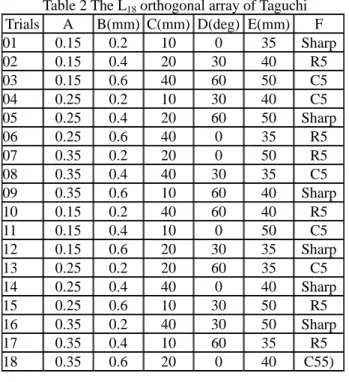
The design parameters of the backward cylindrical
cup extrusion process were studied via the Taguchi method. The considered factors were the height of punch bearing above the punch corner, Hb, the angle of the bearing relief, β, the cut depth of the bearing, Cb, the height of die cavity, Hd, the relief design of die, and the constant shear friction coefficient. The schematic diagram of the tool geometry factors were shown in Fig. 3. The three levels of each factor and the L18(21×37)
orthogonal array for the arrangement of trial combination were given in Table 1 and Table 2, respectively.
Figure 3. The schematic diagram of the design factors Table 1 Design factors and corresponding levels
(A)Friction (B)cutting depth (C)bearing height Level 01 0.15 0.2mm 10mm Level 02 0.25 0.4mm 20mm Level 03 0.35 0.6mm 40mm (D)bearing relief angle (E)height of die cavity (F)Die relief design Level 01 0° 35mm Sharp Level 02 30° 40mm R5mm Level 03 60° 50mm Chamfer C5
The load of the extrusion process was adopted for the quality index of Taguchi method. The goal of the design is the-smaller-the-better. A signal to noise ratio, S/N, was defined as
n
y
N
S
n i i∑
=−
=
1 2log
10
, (1) where n is the test numbers, yi the value of the maximum extrusion load.3.2. One-step approach
A combined extrusion process was adopted to produce the product in a single operation. The diameter of the billet cylinder, Db, was 1 mm smaller than the inscribed circle diameter of the product outer profile as
Hd Rd Relief Design β Rp Hb Cd Outer diameter Inner diameter C C D C-C D-D D 15
(a) The B-B section view of product R3
(b) The A-A section view of tubular body R4 R2 R1 1.35mm C A B C A 125 80 C is the Centroid and profile origin
shown in Fig. 4. The length of billet was calculated by equalizing the volumes of the forged part and the billet.
Table 2 The L18 orthogonal array of Taguchi
Trials A B(mm) C(mm) D(deg) E(mm) F
01 0.15 0.2 10 0 35 Sharp 02 0.15 0.4 20 30 40 R5 03 0.15 0.6 40 60 50 C5 04 0.25 0.2 10 30 40 C5 05 0.25 0.4 20 60 50 Sharp 06 0.25 0.6 40 0 35 R5 07 0.35 0.2 20 0 50 R5 08 0.35 0.4 40 30 35 C5 09 0.35 0.6 10 60 40 Sharp 10 0.15 0.2 40 60 40 R5 11 0.15 0.4 10 0 50 C5 12 0.15 0.6 20 30 35 Sharp 13 0.25 0.2 20 60 35 C5 14 0.25 0.4 40 0 40 Sharp 15 0.25 0.6 10 30 50 R5 16 0.35 0.2 40 30 50 Sharp 17 0.35 0.4 10 60 35 R5 18 0.35 0.6 20 0 40 C55)
Figure 4. The determination of the billet dimension. The bearing profile design is the crucial technique to control the material flow of backward extrusion. The proposed design algorithm of the punch bearing profile is as follows:
(1) Approximation of the non-axisymmetric profile of product - a polynomial equation, f(x), was proposed to fit the outer product profile, where x is the coordinate of the horizontal symmetric axis shown in Fig. 4.
(2) Initial design of the punch bearing profile g(x) - the initial guess of the bearing profile was obtained from
g(x) = w f(x), (2)
where w is an arbitrary weighting value.
(3) Modification of the bearing profile - the height of bearing profile was modified using the predicted
4. Design evaluation
The DEFORM 3D software was adopted to simulate the forming process. The material flow stress model of Aluminum 6061 was expressed with the power law
34 . 0
48
.
311
ε
σ
=
(MPa). (3)The mesh numbers of the workpiece were 40,000. The punch velocity of the forming simulation was 10mm/s. The stroke of the punch was calculated from the tube height of product.
5. Results and discussion
5.1. The two-step approach5.1.1 Preform design and billet dimension
The preform of circular tube was designed using the proposed algorithm. The product outer circumference and the area of section AA in Fig. 1 were 81.54mm and 104.35mm2, respectively. The calculated outer and inner diameters of circular tube were 26mm and 23.3mm, respectively. The billet diameter was 1mm smaller than the outer tube diameter, i.e., 25mm. The volume of the product was 25576 cubic mm and the calculated billet height was 53mm. The punch stroke of extrusion was 53mm by calculating.
5.1.2. Parameter study of the backward extrusion
The loads of the axisymmetric backward extrusion process were predicted according to the parameter combinations given in Table 2. The loads and the calculated signal to noise ratios of the 18 trials were shown in Table 3.
inscribed circle Billet diameter, Db
outer profile of product Billet length, Lb
Db
x
f(x)
Table 3 The extrusion loads (ton)and S/N ratios of trials
Trial 01 02 03 04 05 06 07 Load 26.51 26.97 32.38 33.84 30.71 27.46 37.60 S/N -28.46 -28.62 -30.21 -30.59 -29.75 28.78 -31.51 Trial 08 09 10 11 12 13 14 Load 41.24 35.08 25.66 29.58 28.50 34.90 36.06 S/N -32.31 -30.90 -28.19 -29.42 -29.10 -30.86 -31.14
Trial 15 16 17 18 Predict opt. confirm
Load 32.36 44.61 33.96 46.17 20.46 25.14
S/N -30.20 -32.99 -30.62 -33.29 -27.18 -
The response charts of the design factors depicted in Fig. 5 reveals the effects of friction factor and the die relief design are more significant. The optimum design was obtained from the combination of the highest points of Fig. 5, i.e., the combination of A1B2C1D3E1F2. The predicted and the confirmed optimum extrusion loads of Taguchi method were 20.46 tons and 25.14 tons, respectively. The extrusion load of optimum design was smaller than the other 18 trials, the predicted load and the confirmation trial was in good agreement. The results had demonstrated the feasibility of the Taguchi method. The ANOVA analysis results given in Table 4 revealed the most significant factors were the friction and the die relief. The rounded die relief gave a more smooth
The rounded die relief was adopted for all following designs.
5.1.3. Die designs of the two-step approach
The forming die of preform was designed using the optimum combination found in the previous section. The real complex head was used in stead of the axisymmetric bottom for the die cavity design.
Friction Cutting depth of
bearing
-29.5
-30.5
-31.5
Bearing height Bearing relief angle
-29.5
-30.5
-31.5
Height of die cavity Die relief design
-29.5
-30.5
-31.5
1 2 3 1 2 3 Figure 5. The response chart of design factors
Table 4 ANOVA of the design factors
Source DF S. SS Ad. SS Ad. MS F P C.I. A 2 26.08 26.09 13.04 24.52 0.003 99.7 B 2 0.05 0.05 0.03 0.05 0.952 04.8 C 2 1.12 1.13 0.56 1.06 0.413 58.7 D 2 0.92 0.92 0.46 0.86 0.476 52.4 E 2 1.34 1.34 0.67 1.26 0.362 63.8 F 2 6.40 6.40 3.20 6.01 0.047 95.3 Error 5 2.66 2.66 0.53 Total 17 38.58
Figure 6. The comparison of the part after bending operation and the product section BB. 5.1.4. The geometrical accuracy of the forged part
The cross section of the forming part after finish forming was compared with the section BB of product and shown in Fig. 6. The outer dimensions at the circled areas had a difference ranged from 0.6mm to 1.2mm with respect to the product geometry. The maximum dimension in longitudinal direction of the forming part was 0.87mm larger than the product. The bending effect
of tube at the corner region was the reason of the large dimension deviation at the bottom area of tube.
5.1.5 The forming results of two-step approach
The deformed geometries before and after the finish forming process were shown in Fig. 7. The maximum deviations before and after the finishing process were 1.10mm and 1.21 mm, respectively. The waviness amount increased only 0.11mm in the finishing operation.
Figure 7. The deformed geometry of workpiece before and after the second forming operation
1.10mm
Before finishing operation
After finishing operation
1.21mm
5.2 The one-step approach
The preparation work of this approache is the calculation of the approximated polynomial equation,
f(x), of the product outer profile. The fitted result was
472
.
9
4568
.
0
002
.
0
0046
.
0
0004
.
0
)
(
2 3 4+
−
+
+
−
=
x
x
x
x
x
f
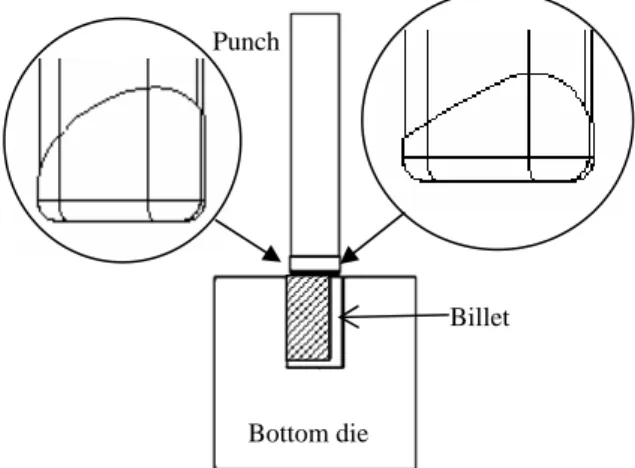
. (3) The initial bearing profile design was base on this equation.5.2.1 The initial bearing profile design and tool setup The initial bearing profile was designed according to the algorithm given in section 3.2 using one for the weighting value, i.e., g(x) is equal to f(x). The result of initial bearing profile design and the tool setup were shown in Fig. 8.
Figure 8. Bearing profiles and die set-up. 5.2.2 The modification of the bearing profile
Bottom die Punch Billet Extruded and bent part 125.87 mm Max.:0.66mm Max.:1.84mm
corresponding waviness profiles were shown in Fig. 9. The maximum edge deviations of the initial guess and modified profiles were 3.18mm and 2.01mm, respectively. A significant improvement of waviness was obtained after modifying. The section views in Fig. 10 displayed the straightness of tubes are good. The velocity distributions shown in Fig. 11 demonstrated the effect of bearing on material flow is very significant.
5.3 The stress and strain c mparison of the proposed stress and strain distribution using the two
.4 The industrial case validation
61 extrusion using one
6.
aring profiles on edge waviness for bac
to an Figure 9. The bearing profiles and edge deviations.
Figure 10.The product section view using the initial and the modified bearing profiles.
Figure 11. The velocity distributions of the different bearing profiles
5.2.3 The application of the bearing profile design The modified bearing profile in Fig. 10b was adopted
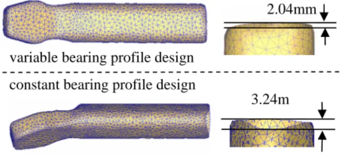
bearing height of 6mm was also conducted to compare the effects of constant and variable bearing profile designs. The final products using the variable and constant bearing profiles were given in Fig. 12 and a significant improvement of the maximum edge deviation from 3.24mm to 2.04mm was observed.
Figure 12.The products by using constant and variable 2.04mm -15 -10 10-5 0 5 -15 5 10 15 0 Initial Modified Product Profile Ini. bearing profile Mod. bearing profile
Waviness of edge
variable bearing profile design constant bearing profile design
3.24m
bearing profiles. o two approaches
The results of
(a) Result of initial bearing
(b) Result of modified bearing
2.01mm 3.18mm
-step and one-step approaches were compared and shown in Fig. 13. The strain of the one-step approach is higher than two-step (before finishing) for the reason of tube symmetry. The maximum effective stress of two-step process (before finishing) was higher than one-step for the reason of larger bearing height (10 mm). 5
The industrial case of AL 60
-step process with a constant 6mm bearing design had been compared with the simulation results. The maximum deviation of the real case is 3.4mm which is closed to the predicted 3.24mm. The deformed results shown in Fig. 14 were in good agreement.
Conclusions
The effects of bekward tube extrusion were discussed in this paper. A bearing profile design and modification method was proposed to improve the waviness condition in case of the uniform bearing design. Two approaches of process and die design method were proposed to take advantages of the bearing effect on the backward extrusion process of axisymmetric and non-axisymmetric tubes.
The proposed design methods were applied
40.5 0.04 13.5 27.0 49.4 0.22 16.6 33.0
(a) Initial bearing profile (b) modified bearing profile
industrial case to control the waviness. The predicted results were in good agreement with the industrial experiment. The edge waviness can be controlled better via the two-step approach. The circumferential accuracy of the one-step approach was better since there is no tube bending effect. The variable bearing profile was able to reduce the edge waviness to 2.04mm which is much better than the case of constant bearing profile.
Figure 13. Stress and strain for one- and two-step approaches with variable bearing profile.
Figure 14. Waviness prediction and validation of an industrial case.
Acknowledgement
The financial supports for this work provided by the J. D. Components Co., Ltd are specially thanked.
References
[1] B. Bennani And J. Oudin, Backward can extrusion of steels_ effects of punch design on flow mode and void volume fraction, Int. J. Mach. Tools & Manufact., vol. 35,1995: 903-911.
[2] K. Kuzman, E. Pfeifer, N. Bay and J. Hunding,
Control of material flow in a combined backward can - forward rod extrusion, J. of Mater. Process. Technol., vol. 60,1996: 141-147 Effective Strain 0.7 1.6 2.5 3.3 264 176 88 0.78
Two-step approach (before finishing)
[3] B. Bennani And N. Bay, Limits of lubrication in backward can extrusion- analysis by the finite-element method and physical modelling experiments, J. of Mater. Process. Technol., vol. 61,1996: 275-286
[4] S.H. Hsiang and C.H. Liao,Study on hot extrusion of tubes, J. of Mater. Process. Technol., vol. 63,1997: 254-259
[5] N.V. Reddy, R.Sethuraman, G.K. Lal, Upper-bound and finite-element analysis of axisymmetric hot extrusion, J. of Mater. Process. Technol., vol. 57,1996: 14-22
Effective Stress (MPa)
[6] Y.M.Gao, Y.Yokouchi, K.Nakanishi, Hot backward extrusion comparative analyses by a combined finite element method, Int. J. Mech. Sci., vol. 42,2000: 1867-1885. 204 136 68.2 0.2 4.78 3.41 2.06 0.68 Effective Stress(MPa) Effective Strain
one-step approach
[7] D.Y. Yang, K. Park, Y.S. Kang, Integrated finite element simulation for the hot extrusion of complicated Al alloy profiles, J. of Mater. Process. Technol., vol. 111,2001: 25-30.
[8] D.Y. Yang, K. Park, Y.S. Kang, Die design and experiments for shaped extrusion under cold and hot condition, J. of Mater. Process. Technol., vol. 190,2007: 375-381
[9] B. Jooybari, A theoretical and experimental study of friction in metal forming by the use of the forward extrusion process,” J. of Mat. Proc. Tech., vol.125-126 (2002) 369-374
[10] Y.-T. Im, S.-H. Kang, J.-S. Cheon and J.-H. Lee, Finite element simulation of tip test with an aluminum alloy, J. Mat. Process. Technol., vol. 157-158,2004:171-196
[11] S.H. Kim, S.W. Chung and S. Padmanaban, Investigation of lubrication effect on the backward extrusion of thin-walled rectangular aluminum case with large aspect ratio, J. of Mater. Process. Technol., vol. 180,2006: 185-196
[12] R.Ye. Lapovok, M.R. Barnett and C.H.J. Davies,” Construction of extrusion limit diagram for AZ31 magnesium alloy by FE simulation,” J. of Mater. Process. Technol., vol.146,2004: 408–414.
[13] N. Ogawa, M. Shiomi and K. Osakada, Forming limit of magnesium alloy at elevated temperatures for precision forging, Int. J. Mach. Tools Manufact., vol. 42,2002: 607-614.
Contact info:
J.J. Sheu (JinnJong Sheu) Professor;
National Kaohsiung University of Applied Sciences, Department of Mold and Die Engineering,
415 Chien Kung Road, Kaohsiung 807, Taiwan, R.O.C. TEL: +886-7-3814526 ext 5406