Design and Control of a Topology Optimal Compliant Microgripper
Dain-Yong Lin 1, Shyh-Chour Huang2 1.Department of Mechanical Engineering National Kaohsiung University of Applied Sciences
2.Kaohsiung, Taiwan, R.O.C. E-mail: [email protected]
Abstract
This paper presents a new method of using the theory of topology optimization and PID control theory to design a microgripper system, with a piezoelectric ceramic driver (PZT) microactuator. This study uses a PZT of 5 mm length, 3 mm width, and 0.5 mm thickness, and analyzes the different performances under the application of different voltages. This study defines a compliant amplifier design domain as 9.2 mm × 8.1 mm, with a 0.5 mm thickness, and discusses the effects of different optimization parameters. The driver is a PZT, which can actuate 10.46μm output displacement of the compliant microgripper. A PID controller is designed for the system, and obtains an improvement of the hysteretic characteristics and control performance of the system.
Keywords: Microactuator, Microgripper, PID Control, Compliant Mechanisms.
1. Introduction
Recently, microscale sensing and micromanipulation have become challenging issues in the development of micro assembly and bio-manipulation systems. The Micro-Electro-Mechanical System (MEMS) is a rapidly growing research area, and refers to a scientific field of studies involving electrical and mechanical functions in hybrid microscale devices, ranging in size from few millimeters to nanometers. The potential advantage of miniaturization using the MEMS approach is the ability to scale down macro components into mass-produced, compact and unitized microsystem devices. As the trend towards miniaturization continues, the microgripper will become an indispensable tool for handling, manipulating and assembling micro components from various application fields.
Micro-gripping devices have many uses; in particular, they are required for microscale assembly of microscale parts made from different types of materials, and by various micromachining processes. Early work with microgrippers employed parallel electrostatic plates to drive the gripper, however, this required relatively a large voltage, and the objects that could be grasped were limited [1-2]. Many kinds of microgripper were used and various types of materials, fabrication methods, actuators, and grasp force were investigated [3-5]. Microgrippers have also been constructed from shape memory alloys (SMA), however, there are problems that must be overcome, e.g. the thermal mechanical constitute relationship of SMA [6-7].
In this paper, we present a design method for microgrippers, with microactuator control, which includes topology optimization, structure analysis, fabrication, and control. This study uses a topology optimum compliant mechanism and a piezoelectric microactuator to design a microgripper. The concept of topology optimization gives rise to a design method of a compliant mechanism. The compliant mechanism of the microgripper is made by a SU-8 thick photoresist.
This microgripper is driven from a PZT microactuator that produces movement in the compliant mechanism. PZT microactuators are solid-state devices that offer the advantages of high energy density and high output force, when compared with conventional methods of actuation.
A feedback-sensor-based manipulation is necessary to realize efficient and reliable handling of micro objects under uncertain environments [8-9]. Achieving high precision-gripping performance requires a reliable actuation mechanism and an effective control method, which considers the dynamics of the microgripper, is earnestly required [10-13]. The design, implementation and validation of the proposed microgripper control method consist of a PID controller for position control. The proposed controllers are successfully applied for real-time control of the developed microgripper, and overcome hysteresis of the PZT actuator. The controllers achieve good control, reduce system errors, and increase the grasping steadiness in order to obtain the best results.
2. Topology optimal design the microgripper
The topology optimization concept first defines the “design domain”, and then divides the domain into several finite elements. These elements consist of variables, which provide the truss element “ground structure parameterization”. Next, by applying the optimization theory, determine which elements remain. The Ground Structure Parameterization method of topology optimization and Sequential Quadratic Programming (SQP) method design a flexible mechanism that can achieve optimum input and output.
2.1 Topology optimal theory
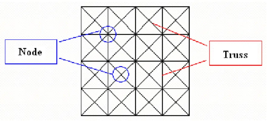
Frame elements have the capability to deform both in longitudinal and transverse directions; and therefore, can incorporate bending modes. The theory of ground structure parameterization is recommended for topology synthesis using truss, beam or frame elements. The ground structure parameterization is a set of elements in a grid of points where each point is connected to every other point, shown in Fig. 1.
Fig. 1 Design domain of the ground structure
The work done by the applied external force is often used as a measure of the stiffness of a structure. Optimization can be expressed by a function called “Strain Energy” (SE) [14].
1
2
SE
dv
v
σε
= ∫
(1) where the σ is stress field and ε is strain field.
A structure problem demands the output displacement at a specific port. The optimization can be expressed by a function called “Mutual Strain Energy” (MSE). A unit of virtual force is applied at an output port in the direction of the desired deformation. MSE is used as the measure of flexibility [14]:
T
M SE
d
dv
v
σ ε
= ∫
(2)
where σd is the stress field.
It is necessary to obtain the gradient of SE and MSE because the gradient of the object function is required to resolve the optimization problem. Obtaining the desired stiffness for the structure is applied in the load; the optimization problem is just a single object function for minimum SE. Therefore, when the structure exhibits maximum stiffness and generates displacement at a specific port, the optimization problem must be a multi-criteria object function of the minimum SE and the maximum MSE. This study considers the output displacement at two specific ports. We need to maximize MSE and minimize SE. MSE and SE can be combined in a ratio-type formulation as:
minimize:
( x )
iS E
M S E
ϕ
=
(3) Subject to:g
1(
x
i)
=
−
x
i≤
0
(4)g
2(
x
i)
=
x
i−
1
≤
0
(5)(
)
0
(6) 1≤
−
=
∑
= C n i i ix
A
L
x
h
where Li is the length variable of the truss element, n is the truss number from the design domain, and A is the limit area of the truss. SE is the strain energy, while external force is applied; and MSE is the mutual strain energy, while unit virtual force is applied at output ports. In this context, the thickness of the device is fixed, thus, the only variables are width and length.
The terms xi and Ac are design variables; xi represents the width of every truss element; Ac represents the limitation of the area of cross section of each truss element. The optimization result for a truss width is xi (0< xi <1). When the width and the cross-section dimension of the element reaches zero, then it is known which element should be removed. Therefore, the optimal topology configuration appears once truss width is known. This optimum structure will transform the motion and force at specific input and output ports, thus, it can be called an “optimal mechanism”. This optimal mechanism has the optimal design between the flexibility and stiffness. In other words, this compliant mechanism not only can generate larger displacement at specific ports, but also has enough stiffness when it supports the load.
The problem, as defined by equations (3) to (6), is nonlinear. This study uses the Sequential Quadratic Programming (SQP) to resolve this problem. The optimality property is first verified with the solution obtained using the SQP algorithm, nonlinear optimization problems can be solved by linear approximation. The problem can be expanded as [15]:
(
)
0 ( ) ( 0) ( 0 ) 1 0 .5 0 1 x n f f x f x xi x i i x i n xi x i i ∂ ∑ = + − = ∂ ∑ + − =⎛
⎞
⎜
⎟
⎝
⎠
(7) Subject to: 0 ( 0 ) ( 0 ) 0 1 x g n j g j x xi x i i x i ∂ ∑ + − = ∂⎛
⎞
⎜
⎟
⎝
⎠
≤ (8)To solve this linear problem, one should give an initial value to x0i and thus solve the new variable xi. This method is less troublesome, easily defines the variables of design parameters, and reduces computer calculation time, and obtains a smoother, clearer, and more accurate structure. The solution procedure of the optimization problem is shown in Fig. 2.
2.2
Design and analysis of the microgripperThe design domain of topology optimization means to define a configuration of a mechanism. The parameters defined are shown in Tab. 1. Given the material type, the methods of building a structure in MEMS fabrication are deposit and etching. In order to simplify fabrication and provide enough flexibility and thickness for the compliant mechanism of this micro-compliant amplifier, this study uses the SU-8 photoresister, which has Young’s modulus E = 4.4 GPa and the Poisson ratio ν = 0.22 [16].
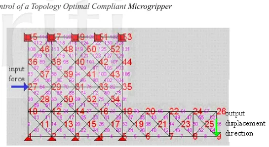
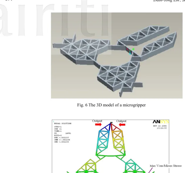
In the process of solving the optimization problem, the ANSYS software package is used to obtain SE and MSE; MATLAB is used to solve the optimization. Fig. 3 shows the design process, design domain, and input and output relation of topology optimization for designing a compliant microgripper. The result of topology optimization, after about 343 iterations, is shown in Fig. 4. The width of every truss element is different, ranging from 0 to 1. The variation in the element sizes shown in the figure actually represents the various truss widths. The object function of the optimization process is shown in Fig. 5, and the 3D model of a microgripper is shown in Fig. 6.
After obtaining the topology optimization profile, this study uses ANSYS software to build and simulate the model. The simulation results of the microgripper are shown in Fig. 7, the output displacement is 21.26 μm for the PZT microactuator at an input displacement of 12 μm, and the maximum stress is 62.2 MPa, as shown in Fig. 8.
Convergence
Define problem (size, input, output.)
Create optimization model
Obtain the gradient of optimization model
Given initial design variable
Fig. 2 The solution procedures of optimization problem[15]
Tab. 1 Design domain specifications
Domain size (µm) Material Divided size (µm)
4000×8000 SU-8 thick photoresist 1000×1000
Spring constants Actuated force thickness
50~250µN/µm 6000μN 500μm
Add the initial variable to obtain new variable for the next iterance
Use ANSYS to obtain SE and MSE
Solve by SLP of MATLAB
Fig. 3 The process for solving the optimization problem.
Fig.4 The results of topology optimization
Fig. 6 The 3D model of a microgripper
Fig. 7 The simulation of a microgripper
2.3 Fabrication of the microgripper
Microgrippers have been successfully fabricated by Photolithography, which is one of the most crucial methods that enable the realization of MEMS devices. The main task of the process is to transfer the mask pattern onto the thin films deposited on wafer surfaces. This is done by completing common sequence steps in a photolithography room.
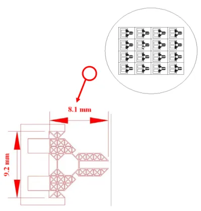
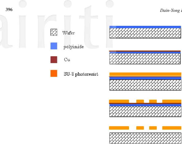
The structural material of a compliant mechanism is modeled by SU-8 photoresistant thick film. In fabricating a compliant mechanism, first, sputter the intermediary (Cu) on the polyimide, and spin coat a 500μm thickness of SU-8 on it. Use lithography to obtain the SU-8 structure of the compliant mechanism. As a result, you can release the compliant mechanism, via removal of the polyimide and intermediary. Fig. 9 shows the mask of a microgripper. Fig. 10 shows the fabrication process. Fig. 11 shows SEM photo of a microgripper. The thickness of the structure is 500μm, and the size of microgripper is 9200μm×8100μm.
Fig. 10 The fabrication process.
3. Piezoelectric ceramic microactuator
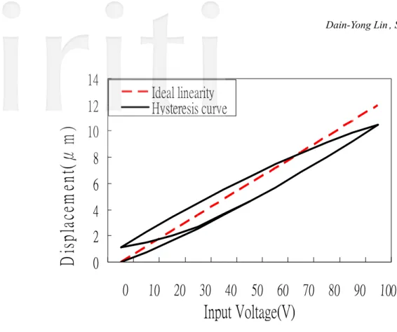
This study uses a PZT driver to generate force. The total dimensions of the PZT microactuator are within a 5000μm x 3000μm area, with a thickness of 500μm. The simulation by ANSYS software is shown in Fig. 12. We measured the output displacement of the microactuator. Fig. 13 shows the schematic diagram of the experimental setup. The output displacement of the microactuator relates to the different applied voltages, as shown in Fig. 14, where it can be found that the PZT microactuator has hysteresis characteristics, and the ideal linearity shows the simulation result [17-19].
output direction
Fig. 12 The simulation of a PZT actuator
0
2
4
6
8
10
12
14
0
10 20 30 40 50 60 70 80 90 100
Input Voltage(V)
Di
sp
la
ce
m
en
t(
μ
m
)
Ideal linearity
Hysteresis curve
Fig. 14 The displacement of the microactuator with different applied voltages
4. Control simulation and experiment
4.1 System identificationWe use a system identification method to determine the model of the PZT microactuator. The commercial software, LabVIEW, and an NI-6014 DAQ card are used for modeling. In the procedure, this study uses a strain gauge to measure the ceramics piezoelectricity microactuator displacement signal, then a MATLAB ARX (Auto-Regressive eXogeneous) toolbox is used to build the system model [20]. Fig. 15 shows the system identification results, the identification percentage is 96.8%.
Fig. 15 The system identification results 4.2 Control system simulation
This study uses a PID controller to control the system [21-23]. Since the invention of the PID control in 1910, its popularity has grown tremendously. PID controllers are widely used in many industries, particularly in processing industries. The popularity of PID controllers is due to their functional simplicity and reliability, as they provide robust and reliable performance for most systems when the PID parameters are properly determined or tuned to ensure a satisfactory closed-loop performance, as follows.
0
1
( )
( )
( )
( )
t P id
u t
K e t
e
d
T
e t
T
τ τ
d
⎡
⎤
=
⎢
+
+
⎥
⎣
∫
dt
⎦
(9)( )
1 (1 0 ) 1 1 ( p I D p D i K s K K K s s K T s T s = + + ⎛ ⎞ = ⎜ + + ⎟ ⎝ ⎠ 1 1)Where u(t) and e(t) denote the control and error signals, respectively, KP is the proportional gain, KI is the integral gain, KD is the derivative gain, Ti is the integral time constant, and TD is the derivative time constant. Fig. 16 shows the PID control basic type.
Fig. 16 PID control basic type
The system block diagram is shown in Fig. 17. The most difficult procedure of using a PID controller is to design the parameters. There is no set rule to select the parameters. After several simulations, we choose KP =10, Td = 0.0004, Ti = 0.0001 for the system. The simulation results are shown in Fig. 18; however, the results were not good. The percent overshoot in the system was 54%.
Fig. 18 PID control simulation results (KP=10, Td=0.0004, Ti=0.0001)
4.3 PID controller parameter experiment
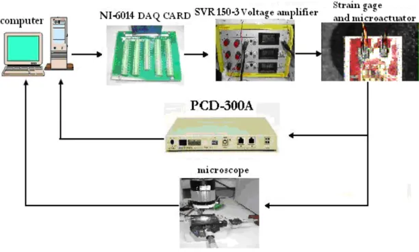
The next step is to use MATLAB software to write PID controller procedures to control the output voltage. Fig. 19 shows the hardware structure block diagram of the experiment, and Fig. 20 shows the picture of the hardware structure of the experiment.
Fig. 20 A picture of the hardware structure of this experiment
Fig. 21 shows the unit-step graph of this experiment and simulation. Fig. 22 shows the unit-step PID control graph of this experiment and simulation (P=20.299. I=0.004, D=0.0001). Fig. 23 shows the Microgripper Integrated Microactuator. Fig. 24 shows the experiment of the microgripper displacement. From Fig. 24, we can find that the system has hysteresis characteristics, while there is no PID controller in the microgripper. The microgripper can produce about 18.8 μm of output displacement, when a 100V voltage is applied.
Fig. 22 PID control step response.
Fig. 24 Experiment of microgripper displacement
5.
Conclusion
In this paper, the compliant mechanism uses a SU-8 photo resist element. This micro compliant microgripper can produce about 20μm output displacement, when a 100V voltage is applied. A PID controller was developed and successfully applied to control the position of PZT actuators. The experimental evaluation shows that the PID controller can achieve good tracking with respect to reference input signals, and therefore, can compensate for the hysteresis phenomenon of PZT actuators. The proposed PID controller was proved to have better performance by experiment.
Acknowledgment
The authors would like to thank the National Science Council of the Republic of China, Taiwan for financially supporting this research under Contract No. NSC 95-2221-E-151-010.
Reference
[1] Chu, P. B., and Pister, K. S. J., “Analysis of Closed-loop Control of Parallel-Plate Electrostatic Microgripper,” Proceedings of the IEEE International Conference on Robotics and Automation, Vol. 1, 8-13, pp.820-825, May 1994.
[2] Keoschkerjan, R. and Wurmus, H., “A Novel Microgripper with Parallel Movement of Gripper Arms,” 8th International Conference on New Actuators, pp. 321-324, June 10-12 2002.
[3] Kim, C. J., Pisano, A. P., and Muller, R. S., “Silicon-processed Overhanging Microgripper,” J. Microelectromech. Syst. Vol. pp. 31–36, 1992.
[4] Nguyen, N. T., Ho, S. S and Low, C. L. N, “A polymeric Microgripper with Integrated Thermal Actuator,” J. Micromech. Microeng., pp. 969-974, 2004.
Microassembly and Micromanipulation,” Microsyst. Technol., pp. 275–280, 2004.
[6] lkuta, K., “Micro/Miniature Shape Memory Alloy Actuator,” Proceedings of the 1990 IEEE International Conference on Robotics and Automation. Vol.3, pp. 2156-2161, 1990.
[7] Kohl, M., Krevet, B., and Just, E., “SMA Microgripper System,” Sensors and Actuators, A 97-98, pp.646-652, 2002. [8] Sitti, M., Horighuchi, S., and Hashimoto, H., “Tele-touch Feedback of Surface at the Micro/Nano Scale: Modeling and
Experiments,” Proc. IEEE/RSJ Int. Conf. Robotics and Systems, vol. 2, pp. 882– 888, 1999.
[9] Zhou, Y. and Nelson, B. J., “The Effect of Material Properties and Gripping Force on Micrograsping,” Proc. IEEE Conf. Robotics and Automation, pp. 1115–1120, 2000.
[10] Park, J., Kim, S., Kim, Deok-Ho, Kim, B., Kwon, Sang Joo, Park, Jong-Oh, and Lee, Kyo-Il, “Identification and Control of a Sensorized Microgripper for Micromanipulation, IEEE/ASME Transactions on Mechatronics, Vol. 10, No. 5, pp. 601-606, October, 2005.
[11] Goldfarb, M. and Celanovic, N., “A flexure-based Gripper for Small-scale Manipulation, Robotica Vol. 17, pp. 181–187, 1999. [12] Eisinberg, A., Menciassi, A., Micera, S., Campolo, D., Carrozza, M. C., Dario, P., “PI Force Control of a Microgripper for
Assembling Biomedical Microdevices,” IEEE Proc.-Circuits Devices Syst., Vol. 148, No. 6, pp 348-352, Dec., 2001. [13] Ku, S. and Salcudean, S. E., “Design and Control of a Teleoperated Microgripper for Microsurgery,” International Conference
on Robotics and Automation Minneapolis, Minnesota, pp 889-894, April, 1996.
[14] Saxena, A. and Ananthasuresh, G. K., “On an Optimal Property of Compliant Topologies, Struct Multidisc Opim. 19, pp.36-49, 2000.
[15] Arora, J. S., Introduction to Optimum Design, McGraw-Hill, Singapore, 1989.
[16] Despont, M., Lorenz, H., Fahmi, N., Brugger, J., Renaud, P., and Vettiger, P., “High-Aspect-Ratio, Ultrathick, Negative-Tone Near-UV Photoresist for MEMS Applications,” Proc. IEEE Microelectromech. Syst. Workshop, pp.518-522, 1997.
[17] Choi, G. S., Fim, H. and Choi, G.. H., “A Study on Position Control of Piezoelectric Actuators, IEEE Catalog Number: 97TH8280, pp 851-855, 1997.
[18] Ge, P., and Jouaneh, M., “Tracking Control of a Piezoceramic Actuator,” IEEE Transactions on Control Systems Technology, Vol. 4, No. 3, pp209-216, May, 1996.
[19] Low, T. S., and Guo, W., “Modeling of' a Three-Layer Piezoelectric Bimorph Beam with Hysteresis , Journal of Micro-electromechanical Systems, Vol. 4, No. 4, pp230-238, Dec. 1995.
[20] Ohata, A., Furuta, K. and Nita, H., “Identification of Nonlinear ARX Model with Input and Output Dependent Coefficients,” Proceedings of the 2006 IEEE International Conference on Control Applications, Munich, Germany, pp 2577-2582, October 4-6, 2006.
[21] Astrom, K. J., and Haglund, T., Automatic Tuning of PID Controllers, 1st ed. Research Triangle Park, NC: Instrum. Soc. Amer., 1988.
[22] Astrom, K. J., and Haglund, T., PID Controllers: Theory, Design and Tuning, 2nd ed. Research Triangle Park, NC: Instrum. Soc. Amer., 1995.
[23] Basilio, J. C., and Matos, S. R., “Design of PI and PID Controllers With Transient Performance Specification,” IEEE Transactions on Eduaction, Vol. 45, No. 4, pp.364-370, Nov., 2002.
[24] Ziegler, J. G., and Nichols, N. B., “Optimal Settings for Automatic Controllers,” Trans. Amer. Soc. Mech. Eng., Vol. 64, pp. 759-768, 1942.