A VLSI Architecture Design of VLC Encoder for High
Data Rate VideoDmage Coding
Hao-Chieh Chang, Liang-Gee Chen, Yung-Chi Chang and Sheng-Chieh Huang DSPAC Design Lab, Department of Electrical Engineering
National Taiwan University Taipei, Taiwan, R.O.C.
ABSTRACT
An efficient architecture of variable length coding (VLC) is developed for recently multimedia applications, such as video and image compression. VLC plays a crucial part in these applications in that it provides a very effective coding gain. In this paper, we will describe an architecture design of VLC encoder. It can produce VLC codeword and amplitude, and pack them in order to achieve the constant word-length output. In addition, in this pipeline architecture, the VLC codeword and the amplitude can be processed in one clock cycle such that the input data rate of VLC encoder can reach as high as the sampling rate of videohmage data. Therefore, it is very suitable for very high data rate video and image compression applications.
Keyword: VLSI architecture, VLC, Video/Image coding
1.
INTRODUCTION
VLC is a widely used technique for data compression because of its high compression efficiency and simple algorithm. It has been adopted as a part of many international image and video coding standards, such as [5], MPEG-4 [6]. VLC is usually used along with RLC and DPCM source coding algorithms to remove the source redundancy further at the final stage of the current coding scheme for video and image data. The RLC can reduce the data rate by representing successive zeros and a successive nonzero value as a symbol that can be coded in a more compact codeword. The higher probability for the occurrence of successive zeros can be achieved by suitable quantization. Whenever a symbol
is determined, a variable-length codeword can be produced by locating it from a pre-defined VLC table. The data rate can be reduced by given shorter codewords to the more probable source symbols. JPEG [l], H.261 [2], H.263 [ 3 ] , MPEG-1 [4], MPEG-2
A VLC encoder is usually realized by using a table look-up implementation that maps the input source symbols, produced by DPCM or RLC or any other
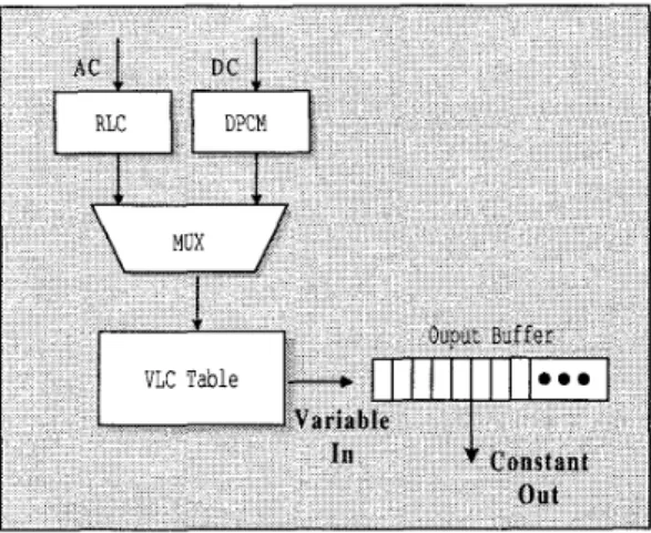
predictors, into codewords. And, these variable-length codewords are concatenated together and then segmented into a suitable word length data, e.g. 16-bit, for constant word-length output. The block diagram of a typical VLC encoder for baseline JPEG encoder is
shown in Figure 1. As shown in Figure 1, a predictor, e.g. DPCM or RLC, first processes input data in order to achieve better source statistical property. An entropy encoder then codes the predicted data and produces variable-length codewords. Variable length output makes the utilization of U 0 bandwidth inefficient, so a codewords concatenator that can produce constant word-length output is strongly demanded for an efficient design.
Figure 1. The block diagram of the VLC encoder architecture used in Baseline JPEG
The concatenation of the variable-length codewords can be done bit-serially. However, using the bit-serial approach will demand very high operating speed at the output stage. This is because each input symbol for VLC encoder may produce several bits of data and force the clock rate of the output stage has to increase up to several multiples of input data rate. It will cause the bottleneck for the data-intensive applications, especially
0-7803-547 1 -0/99/$10.0001999 IEEE
for real-time video applications. Therefore, it is not suitable to use the bit-serial approach for such applications.
A different approach based on parallel operations will be discussed in this paper. The parallel VLC encoder first maps one input symbol into a look-up table and finds a variable-length codeword. Then, the produced codeword is concatenated with previous codewords in the output buffer. The concatenation can be finished in one clock cycle. Using such approach, the encoder can operate at the same rate as input sampling data rate. Hence, the input data rate can be increased for processing data-intensive applications. The previous studies, [7,8], have proposed several parallel VLC encoder architectures. Lei [7] used two barrel shifters for concatenating the codewords and a special barrel shifter as an accumulator to achieve faster operations for accumulation. However, the barrel shifters used in this architecture are large in size. Mario [8] adopted a more compact VLC encoder architecture for packing codewords and amplitude. In this architecture, only one
shifter and one multiplexer are necessary for packing data. However, the control signals of multiplexer become more complex. Either the multiplex control is not detailed in this paper.
In the following, a novel parallel VLC encoder architecture is presented. Then, an analysis of this proposed architecture is described in Section 111. Finally, a brief conclusion is given in Section IV.
2. PARALLEL VLC ENCODER
ARCHITECTURE
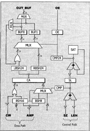
The VLC encoder contains two major parts: a look-up table for producing the variable-length codewords and the output stage for concatenating the codewords. The block diagram of our proposed parallel VLC encoder is shown in Figure 2. The look-up table is usually implemented by a ROM (Read Only Memory), PLA (Programmable Logic Array), or SRAM (Static Random Access Memory). In our design, we adopt the PLA implementation for its flexibility. Since the operation of this look-up table is simple, we do not depict the block of look-up table in Figure 2.
The CW, AMP, SZ and LEN, which are the outputs from the look-up table, transmit codeword, amplitude, size, and length values to the output stage. The output stage first concatenates the codewords and amplitudes to a sequence of bits. When the length of the concatenated bits reaches the output bus width, say 24 bits or so, the output stage then segments the 24-bits data from the
concatenated bit sequence for output. The rest of bit sequence is then concatenated with the next codeword and amplitude. This process repeats until no more codewords and amplitudes are transmitted. As shown in Figure 2, the output stage can be divided into two parts: the data path and the control part. The control part utilizes the SZ and LEN information to make the operation of the data path correct.
The data path mainly consists of the following circuits. Register CA stores the result by concatenating the
codeword and amplitude. Registers BUFO and BUFl are used to store the concatenated data from the register CA
iteratively. BSHI6 and BSH8 shift the AMP so that ihe
AMP can be appended behind the codeword. LBSH24
and RBSH24 are 24-bit barrel shifters that are used to shift the data in register CA in left and right direction respectively. The shifted data is combined with previous concatenated data by using a 24-bit OR-gate to produce the correct concatenation result. The shift amount of the shifters in the data path is controlled by the control part.
Figure 2. The block diagram of the output stage of our
proposed VLC encoder architecture
The control part consists of the following circuits. Register SL stores the sum of the length of a codeword and the size of amplitude. Module SAT is used to record
the length of the current concatenated data in BUFO or BUFI and to detect if this length has reached its maximum value, e.g. 24 in this design. When this length exceeds its maximum value, it will be subtracted by 24 and then be output. Two comparators, CMP16 and CMP24, compare their input with number 16 and 24 respectively. The comparison results are used as the total shifting amount of the barrel shifters in the data path.
LBUF
L E N A
The output stage works as follows. The amplitude (AMP)is first shifted by the shifter BSH16 and BSH8. The shifting amount depends on the result of the comparator CMPI6. The output of the BSH16 combined with codeword (Cw> by a 16-bit OR-gate is loaded into the leftmost 16-bit location of the register CA. An 8-bit multiplexer, that is used to select the output of the BSH8 or zeros, loads its selected data to the rightmost 8-bit location of CA. By these operations, the codeword and amplitude can be concatenated correctly and loaded into the leftmost bits of register CA within one clock cycle.
~
0
12
2
0
4
F
5
C
w
~
r
n
r
n
r
n
Similarly, the data in the register CA is first shifted by
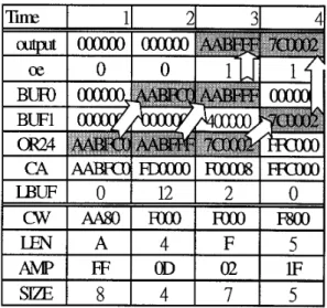
the two 24-bit barrel shifters LBSH24 and RBSH24 depending on the comparison result of the CMP24. A flag is used to indicate the active buffer register, which is the buffer register (BUFO or B U F I ) that stores the previous concatenated data. The previous concatenated data is combined with the data from LBSH24 by using a 24-bit OR-gate. The concatenated data will be stored in the active buffer register until the length of the concatenated data exceeds 24. While such situation happens, the exceeded data will be loaded into the non- active buffer register and the value of the flag will be changed. The data in the previous active buffer register can be output at current time instance. Figure 3 shows
an example that describes the operations.
3. ARCHITECTURE ANALYSIS
The proposed architecture is realized by using a logic synthesis tool and, simulated and analyzed in the gate- level design by using a gate simulation tool. Figure 4 demonstrated the analyzed area and the simulated time- delay of all the used components in our design. Generally, an 8-bit barrier shifter is smaller in area and faster in speed than a 16-bit barrier shifter. We adopt the architecture design that uses a 16-bit barrier shifter, an 8-bit barrier shifter with a few extra controls to replacethe design of two 16-bit barrier shifters with few controls. Also, the word-length of the barrier shifters and the pipelined registers used in this architecture are designed as smaller as possible with the cost of few extra controls. This is the reason why our architecture can achieve a more compact analyzed chip area. The registers BUFO and BUFI switch in a ping-pong mode operation. The correct concatenated codewords will reach at the output OUT-BUF when the control register OE is activated high.
I
I
0
I
0
I
11-11
14;
Figure 3. An example of the output stage operations
Figure 4. Analyzed area and simulated time-delay
of all components used in proposed VLC encoder
architecture.
The critical path happened at the second pipeline stage of the output buffer stage. This path starts from the saturation detection module SAT, the 6-bit adder, the comparator CMP24 in the control part to the multiplexer that multiplex the output of the two 24-bit barrier shifters LBSH and RBSH. The latency of subtractor and adder dominates the overall critical path delay. The SAT is used to check if the buffer length of BUFO or BUF1 exceeds 24. It is composed of a 6-bit register and a 6-bit substractor. Figure 5 compares the analyzed area and simulated time-delay of the critical path in several architectures. Though the critical path delay in our proposed architecture is a little longer than the others listed in Figure 5 , our architecture are much smaller in chip area. This is the most advantage in our design.
Lei’s
[7]
JAGUAR
[8]
4.
CONCLUSION
5.56
10000
5.38
4793
In this paper, an efficient and cost-effective parallel VLC encoder architecture is discussed. It is simulated and analyzed in the gate-level. Compared with previous works, a novel architecture with compact hardware and simple control is described in this paper. The proposed architecture can process the codeword and amplitude in one clock cycle. In addition, it uses more compact hardware resource. Due to these two advantages, it is very suitable for low cost multimedia applications with very high input data rate.
Proposed
5. REFERENCE
5.72
260 1
ISOAEC, Int. Standard DIS 10918, “Digital compression and coding of continuous-tone still images.”
CCITT Study Group XV, TD35, “Draft review of recommendation H.261 video codec f o r audiovisual services at px64 kbitsh,” Image
Communication, pp.22 1-239, August 1990. “Video Coding for narrow telecommunication channels at e 64 kbitsh,” Draft ITU-T Recommendation H.263, July 1995.
Didier Le Gall. “MPEG: A Video Compression Standard f o r Multimedia Applications,” Communications of the ACM, Vol. 34, No. 4, pp.46-58, April 1991
ISO/IEC/JTCl/SC29/WG11 Draft CD 13818-2 Recommendation H.262 Committee Draft.
Sikora, Thomas, “The MPEG-4 Video Standturd Verification Model,” IEEE Transactions on Circuits and Systems for Video Technology, Voll. 7, No. 1, pp. 19-31, February 1997.
S.M. Lei, M. T. Sun, K. Ramachandran and S. Palaniraj, “VLSI Implementation of an Entropy Coder and Decoder f o r Advanced
TV
Applications,” ISCAS ’90, pp. 3030-3033MARIO KOVAC and N. RANGANATHAN, “JAGUAR: A Full Pipelined VLSI Architecture .for JPEG Image Compression Standard”, Proceedings of the IEEE, VOL. 83, NO. 2, FEB. 1995. Shaw-Min Lei and Ming-Ting Sun, “An Entropy Coding System f o r Digital HDTV Applications“, IEEE Transactions on Circuits and Systems for Video Technoology, Vol. I , No. 1, pp.147-154, Mar. 1991.
[IO] Yuji Fukuzawa, Kouichi Hasegawa, Hirokazu Hanaki, Eiji Iwata and Takao Yamazaki, “A programmable VLC Core Architecture f o r Video Compression DSP”, Proc. of IEEE workshop on signal processing systems - Design amd Implementation, pp. 469, Oct. 1997.
[ 1 I ] Tetsuya Matsumura, Hiroshi Segawa, Satoshi Kumaki, et.al, “A Chip Set Architecture .for Programmable Real-Time MPEG-2 Video Encoder”, Proc. of IEEE Custom Integrated Circuits Conference, pp393-396, May 1995.