Proceedings of the 37th IEEE Conference on Decision & Control Tampa, Florida USA December 1998
WM15
13:20
Nonlrliear -4daptive Sensorless
Speed Control
ofInduction
Motors
Ren-Jye Chang
',
Li-Chen Fu
'i2Department
of'
Electrical Engineering'
Department of Computer Science
and
Information Engi:ieering2
National Taiwan University
Taipei, Taiwan, Republic
of
China
Abstract: In this thesis, a nonlinear adaptive sensorless speed controiler for icduc-
tion motors is proposed. In the controller, only the stator currents are assumed tG be measurable. Flux observers and rotor speed eszimator are designed to relax the need
of flux and speed measurement. Besides, an estimator is also designed t o overcome
drifting problem of the rotor resistance.
Nomen
clat
ur
e
{ V,: Vh } are stator voltages; { I,, 1.5 } are stator cuirents; {
Qa,
$ ~ b } are rotor fluxes; wr is the me-chanical angular speed of the rotor;
R,
is the stator resistance; R,. is the rotor resistance; L, is the stator self-inductance: L , is tile rotor self-inductance; M isthe mutual inductance; p is the number of pole-pairs; J
is the rotor inertia; D is the damping coefficient; TL is
the load torque; k~ is the torque constant (=%);
Lo
L2
equals t o +;PL, - @); equals t o
q;
~2 equals t oL-
P L r ; ,& equals to
3
L'1
Introduction
In early years of the induction motor control, all sys- tem states are assumed to be measurable and param- eters are assumed to be known. Under these assump- tions, classical field-oriented [I] and input-output lin- earizing control technique [ 2 ] [3] are utilized t o design
the controller. Since in these schemes the flux sensors are required, this makes it impractical for implementa- tion. Therefore flux observers are then designed t o relax
the need of flux measurement [4] [5]. Because observers
the rotor resistance and/or other system parameters [6]
[7]. After these researches, engineers nowadays try t o
design controllers and flux observers which are adap-
tive with respect t o both system parameters and/or the
load. There are many researches published, such as
[e]
[16] [19] and [20]. All schemes above require speed mea-
surement which violates the advantages of induction me- tors.Therefore. controllers that speed measurement are not required are preferable for practical irr'plementation. The problem that t o design a speed controller for in- duction motors without rotational transducers is then getting more and more popular and is usually called
sensorless control prob!em. Th e first paper regarding
sensorless control probleni was presented in 1981 a t a n.z- tional conference in Japan. In this paper, vector control is utilized. After the presentatioii of this paper, many researches about sensorless vector control are proposed
[12] [15]. In these researches, the analysis are mainly
based on the steady state and proves are I I Q ~ discussed
in detail. In all researches about sensxless contrcl for induction mocors, modern control theory such as robust, MRAS (Model Reference Adaptive System) is another popular trend. Here we follow this trend to design a;l adaptive sensorless speed contro!lcr for induction motors based on flux observer.
stzitionary a-b reference frame m3del is introduced. In
addition to derivation of the model, two lemmas which
relates the speed tracking with the state tracking are presented and proved. The main part of this thesis is section 3 in which observers and controller are explained aad proved in detail. The experiniental results are pre- sented in section 4. Finaliy, section 5 is the conclusion.
2
Prelliminary and Problem For-
mulation
This sectior. is to briefly review the induction motor model and s8ome useful properties and important basic results which facilitate t.he controller design.
2.1
Motor Model
If the induction motor never goes into the saturation region, and the air-gap M M F is sinusoidal, then it can
be characterized by the following dynamic eyuatioiis :
L o I a = - . M R r I a
-
P l I a+
R r G a + /32wr'$b+
P 3 V a L o I b = - . J v R r I b-
P l I b-
P 2 W r ' $ a R r l / ) b P 3 v bLr.$a = --R,-Qa
+
M R r I a-
P2wr'$b L r 4 b = --Rr.$b+
M R T I b+
P 2 W r G aT e = k T ( ' @ a I b
-
'$bIa) (1)where Lo,
p l ,
P3
are constants defined in thenomenclature. Through some analysis based on New- ton's law, the dzynarnics of the mechanical part is
JW,.
+
Dw,+
T L = T, (2)where J
>
0 is the rotor inertia, D>
0 is the damping coefficient and TL is the load torque.2.2
Preliminaries
The first leirima presented below establishes a relation between the speed tracking problem and the torque tracking problem.
Lemma
1..If the load torque
TL
can be written asTL = PO . s ( k , u r )
+
/ L l W r+
~ 2 W r,
(3) with PO, p1 and p 2 being known positive constants and the sigmoidal function s ( k , w r ) be defined as :T h e n the speed tracking objective (i.e., wr
+
u r d ) can be czchieued provided that the objective of torque trackingProof:
First, note that from (4), the desired torque is
bounded if the desired speed is bounded. Since the sig- moidal function s ( k , x ) is
3
then its first-order derivative g ( k , x ) is
2ke- k . x
g(', x , = (1 + e - k . z ) 2
It is obvious that 0
5
g ( k , x )5
$.
From the Mean- Value theorem,where w E
['w.,
U r d ] , and henceT,-Td = ( J + p 2 ) 6 5 f ( D f r ( L 1 + g ( k , U ) ) % , e5 = W r - u r d
If (T,
-
T d ) approaches t o C asymptotically, e 5 ( t ) ap-proaches to 0 asymptotically, too. Th at is, w,. ap-
The following lemma establishes a relation between the bound on the torque tracking error and the bound ,on the state tracking error.
Lemma
2.
ing form :proaches t o W r d asymptotically. 0
If the desired torque T d can be expressed in the follow-
T d = k T ( ' $ a d I b d - ' $ b d l a d ) r
where I a d ( I b d ) and $ a d ( ' $ b d ) are the desired v a l w s of the a-b axis currents and fluxes: respectively. Then, the bound o n the torque tracking error can be expressed as
I
T . - T d 15v(!Ie112
+
2 llell ! i x d l l ) ,where e is the state tracking error vector and x d is the desired state vector respectively defined as
(5) kT
P r o o f :
This lemma clearly leads to the following corollary.
Corollary
1.
If the state tracking error converges to zero, i.e., e
+
0 , then the torque tracking error:
T,
- T d , converges to zero, too.With the aid of these two lemmas, we see that the speed tracking can be achieved once the state tracking is achieved.
2.3
Problem Formulation
We try to design a speed controller for induction motors,
which does not rely on any shaft sensor outputs and only measures the stator currents. All the parameters of the motor and of the load except the rotor resistance are assumed to be known. Given these information about
the motor, for any speed command which is a second-
order continuously differentiable bounded function, this controller should be able t o drive the motor t o track the command.
3
State Observer and Controller
Before the thorough investigation OD. the observers and
controllers, several assumptions will be presented below t o make the problem more precise.
Assumptions
:( A l ) All parameters of the motor and the load are
known, except the rotor resistance.
(A2) The upper and the lower bounds of the rotor re- sistance are known and are denoted as
z,
and&,
respectively.(A3) The stator currents are measurable.
(A4) The load torque TL is a known function which satisfies that, if T, is bounded, the rotor speed w, is also bounded.
(A5) The desired rotor speed should be a bounded
smooth function with known first and second or-
der time derivatives.
(A6) The rotor speed is slowly varying and wrd - 6,
<
Remark
:It is obvious that w, is bounded once
T,
is assumed to be bounded. In other words, this kind of TL clearly satisfies assumption (A4).Then we begin to introduce our observer and con- troller. For easy reference, define the notations for the
observed values and the observation errors as follows :
wr
<
Urd+
8,.where the symbol A denotes that it is an observed value
and the symbol
-
denotes an observation error. TheDefine the state variables in a more compact form :
then the state equations can b e written concisely in a matrix form as follows:
X = (A0
+
A ~ ) z+
BU where 0 kt LO 00'
J
L o
0 Note that the matrix A0 is a negative-definite matrix.Theorem
1.
Consider a n induction m o t o r whose dynamics is gov- erned b y ( I ) under assumptions ( A l ) to ( A S ) If the sta-
tor current observers and the rotor flux observers are designed as in (6), then the mechanical angular speed
of the rotor w, will be driven t o approach to a bounded
and the rotor speed observer and the rotor resistance o bserver
for some constants
where
and the initial conditions of Rr and br satisfying
&(o)
>
xi- +
6 R , G r ( 0 )>
w r d ( 0 )+
6,Proof:
Select the Lyapunov function candidate as :
' T
V , - 2 - - e Gel G = diag [ g l , 91, g2, 921
v
=v,
+
v,
for some constants k,, k,, k R , 91, 9 2
>
0 , then its timeBy properly assigning positive cons'tants 91, 9 2 and kl,
we can make V as well as -V both become positive func-
tions. A sufficient condition for the value of constant kl
is
According to (7) and standard Lyapunov stability the-
ory [13], observation errors
,
parameter estimation errorand state tracking errors are all bounded. Besides, from Corollary 2 , the desired state trajectories l a d , I b d , '$'ad
and '$bd are all bounded. Since the desired states and
the state tracking errors are all bounded, the system states l a , I b , '$, and '$b are all bounded. Consider-
ing the definition of the auxiliary error signals
2,
andz b , since the stator current observation errors
I,
and16 are both bounded, the rotor flux observation errors
4,
and ?jb are bounded, too. So far, we know that thetrue system states and their observation errors aJe $1 bounded, which implies that the observed values I ,
,
I b ,4,
and 4 b are then bounded. Recall that all auxiliarycontrol signals uol to uO4 and u,l, u,2, w e l l , ~ ~ 1 2 , 21,21, ' 0 ~ 2 2 are combinations of states, observed signals and ob-
servation errors and hence are all bounded. Moreover, from the dynamic model ( I ) , the generated torque is a combination of system states, and therefore it is also a bounded function. Then, by assumption (A4) the rotor speed w, is bounded, which implies that G, is bounded since 6 , is bounded. As t o the rotor resistance estima-
tor, since the true value is bounded naturally and the estima_tion error is proved t o be bounded, the estimated value R, is bounded. This means that all internal signals are bounded functions. Consequently, the observer and the controller design introduced above is indeed feasible and well defined. Follow a similar analysis as Barbalat's Lemma [14], we will obtain the result
I,,
f b , e l , e 2 , e 3 , e4 -+ 0, as t -+ 00referring to Lemma 2 in the previous chapter together with the result above, we see that the torque tracking objective is then achieved
T, -+ T~ as t -+
ob
which in turn, implies that the speed tracking error con- verges to zero, too, i.e.,
e 5 + O a s t - + c o
j W , - + W , d a s t - + c o
from Lemma 1. This completes the stability analysis of the overall system.
4
Experimental Result
Experiments are done with a three horse power induc-
tion motor which is manufactured by TECO 00. Ltd.
Taiwan. Parameters of the motor are listed in table 4.1.
SDecification Parameter Poles 4 R, 0.83 R Rated current 8.6 A R, 0.53 R Rated voltage 220 V L , 86.01 mH Rated frequency 60 Hz L , 86.01 mH Rated Speed 1720 RP M M 82.59 mH Rated power ~ 2.2 KW J 0.033 kg
.
m2 0.00825 N . m . s Table 1. Specifications and Parameters of the MotorD
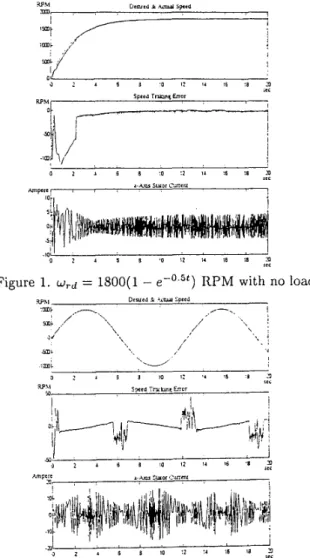
In order to check the performance, we have done two experiments with exponential and sinusoidal speed coni- mand as in figure 1 and figure 2 .
Obviously, experiments show that the sensorless con- troller is indeed effective t o drive the motor to track a given smooth speed command.
WM O m e l l k ~d Lmcd
0 2 1 5 S .O !2 !4 16 :6 9 ,I<
Figure 1. w,d = 1800( 1 - RPM with no load
.ai
,,
' , I3 :2 :a 16 ia st< 3
ci
Cordusion
In this paper, we have presented a singularity-free,
partial-state feedback adaptive sensorless speed track- ing controller for induction motors with fifth-order non- iinear dynamic model which is actuated by a voltage source. The main contribution of the controller is that asymptotic rotor speed tracking is achieved without measurement of both the rotor fluxes and the rotor speed. Moreover, the variation of the rotor resistance is also taken into account. In addition t o the rotor speed, we can also control the norm of the rotor fluxes to track a given constant value. However, the controller is not free of defects. The main weakness of this controller is that the rotor speed is assumed t o be slowly vary-
ing and the difference between it and the desired speed
command s:nould be less than or equal t o a bound 6,.
References
[I] W. Leonhard, ”Microcomputer Control of High Dy-
namic Performance Ac-Drives-a Survey”
, Automat-
ica, Vol. 22, pp. 1-19, 1986.
[ 2 ] A . D. Luca and G. Ulivi, ”Design of an Exact
Nonlinear Controller for Induction Motors”, I E E E Trans. on Automatic Control, Vol. 34, No. 12, pp.
[3] R. Marino, S. Peresada and P. Valigi, ”Adaptive
Input-Output Linearizing Control of Induction Mo- tors”, l E E E Trans. on Automatic Control, Vol. 38, [4] A. Bellini, G. Figalli and G. Ulivi, “Analysis and
Design of a Microcomputer- Based Observer for an
Induction Machine”
,
Automatica, Vol. 24, pp. 549-555, 1988.
[5] G. C. Verghese and S. R. Sanders, ”Observers for
Flux Ektimation in Induction Machines”
,
I E E ETrans. on Industrial Electronics, Vol. 35, pp. 85-94,
1988.
[6] J. Stephan, M. Bodson and J. Chiasson, ”Real-Time Estimation of the Parameters and Fluxes of Induc- tion Motors”
,
I E E E Trans. on Industrial Applica- tio.ns, Vol. 30, No. 3, pp. 746-758, 1994.[7] R. Marino, S . Peresada and P. Tomei, ”Exponen-
tially Convergent Rotor Resistance Estimation for Induction Motors”, I E E E Trans. on Industrial Elec- tronics, Vol. 42, No. 5, pp. 508-515, 1995.
[8] J. H u a.nd D. M. Dawson, ”Adaptive Control of In-
duction Motor Systems Despite Rotor Resistance
Uncertainty”
, Proceedings of the American Control
Conference, Jun. 1996, pp. 1397-1402
[9] G. Espinosa and R. Ortega, ”State Observers are
unnecessary for Induction Motor Control”, Systems
& Conirol Letters, Vol. 23, No. 5, 1994, pp. 315-323
1304-1307, 1989.
pp. 208-221, 1993.
[lo] A . M. Lee and L. C. Fu, ”Nonlinear Adaptive Speed
and Torque Control of Induction Motors with Un-
known Rotor Resistance”
,
Master Thesis NationalTaiwan University Taiwan R.O.C., 1996.
[ 111 P. C. Krause, ” Analysis of Electric Machinery”
,
Book McGraw-Hill 1987.
[12] T. Ohtani, N. Takada and K. Tanaka, ”Vector Con-
trol of Induction Motor without Shaft Encoder”,
I E E E Trans. on Industrial Application, Vol. 28, NO. 1, Jan./Feb. 1992, pp. 157-164.
[13] M. Vidyasagar, “Nonlinear System Analysis”
,
En-glewood Cliffs, NJ: Prentice-Hall, 1992.
[14] K. S. Narendra, A. M. Annaswamy, ”Stable Adap-
tive Systems”
,
Englewood Cliffs, NJ: Prentice-Hall,1989.
[15] H. Kubota and K . Matsuse, ”Speed Sensorless
Field-Oriented Control of Induction Motor with Ro-
tor Resistance Adaptation”
,
IEEE Trans. on Indus-trial Application, Vol. 30, No. 5 , Sep./Oct. 1994, pp.
[16] Jung-Hua Yang, Wen-Hai Yu, and Li-Chen
Fu, ”Nonlinear Observer-Based Adaptive Tracking
Control for Induction Motors with Unknown Load”
,
I E E E Trans on Industrial Electronics, Vol. 42, NO. 6, Dec. 1995, pp. 579-586.
[17] C. Has, A . Bettini, L. Feraris, G. Griva and F. Pro-
fumo,
’’
Comparison of Different Schemes withoutShaft Sensors for Field Oriented Control Drives‘’,
Proceedings of I E E E IECON’94, pp. 1579-1588,
1994.
[18] T. H. Chin, ”Approaches for Vector Control of In-
duction Motor without Speed Sensors”
, Proceedings
of I E E E IECON’94, pp. 1616-1620, 1994.
[19] R. Marino, S. Peresada and P. Tomei, ”Adaptive
Observer-Based Control of Induction Motors with
Unknown Rotor Resistance”
,
IEEE InternationalJournal of Adaptive Control and Signal Processing,
[20] R. Marino, S. Peresada and P. Tomei, ”Global
Adaptive Output Feedback Control of Induction
Motors with Uncertain Rotor Resistance”
,
Proceed-ings of the 35th Conference on Decision and Con- trol, pp. 4701-4706, 1996.
12 19- 1224.