Design and Analysis
of a Hierarchical and
Modular Local
ATM
Switch
tZsehong Tsai, ZKangyei
Yu,
and tFeipei Lai
+Department of Electrical Engineering
National Taiwan University
Taipei, Taiwan,
R.O.C.
Abstract
In this paper, we propose a hierarchical and modu- lar local ATM switch. In order to improve the queue- ing performance, we adopt the output queueing tech- nique and allow several outputs to partially share the same output buffer space. The perfomance of the proposed switch i s evaluated under uniform and non- uniform trafic patterns. c o m arisons with Knockout Switch[2], Recursive Switch[SfP SCOQ[d], and Christ- mas Tree Switch[5] have shown that in t e m of com- plezity, crosstalk, scalability and synchronization, the proposed switch is superior t o the others.
1
Introduction
Local Area Networks (LANs) have completed t- wo generations of development. A third generation LAN should provide real-time transport capabilities, scalable throughput, inter-working between LAN and wide area network. Among numerous approaches t o meet the above criterias, the ATM (Asynchronous Transfer Mode) seems t o be the most promising. AT- M has been selected by international standard bodies
as the basis for future B-ISDN (Broadband Integrat- ed Services Digital Network). Thus, if we construct future LANs on ATM, we can benefit from common standards and protocols, as well as widely available hardware and software components. At the same time, the local ATM (LATM) networks can still easily con- nect t o the future broadband networks.
A large number of switching fabrics have been pro- posed t o implement a n ATM switch, and they are all developed for B-ISDN. For LATM switch, there are some differences in service requirements. For exam- ples, a LATM switch provides only below 1000 ports, due t o the fact that it is located in the LAN environ-
ment. Delays in the switches themselves will domi- nate link delays, so the switching delay is much more important. Because the interconnections among hosts and switches are all point-to-point links, LATM switch must own both multicast and broadcast capabilities[l]. Beside the above differences, the design concept of AT-
M
switch (B-ISDN) is the same as LATM’s.The ATM switches can be classified into two cat- egories: (1) Time division, ( 2 ) Space division. In a switch fabric based upon time division, all.cells flow across a single communication highway shared in com- mon by all input and output ports. This communica-
$Department
of
Product Development
Siemens Telecomm. System Limited
Taoyuan, Taiwan,
R.O.C.
tion highway may be either a shared medium such as
a ring or a bus[6, 71, or a shared memory[8, 91. The throughput of this single shared highway defines the capacity of the entire switching fabric and thus fixes an upper bound on the capacity for a particular im- plementation beyond which it can not grow.
Whereas in time division, a single communication highway is shared by all input and output ports, in space division, a plurality of paths is provided be- tween the input and output ports. These paths op- erate concurrently so that many cells can be trans- mitted across the switching fabric at the same time. The upper bound of the total capacity of the switching fabric is therefore theoretically unlimited. In practice, however, it is restricted by physical implementation constraints (e.g., device pinout, complexity, synchro- nization and crosstalk considerations), which together
limit the size of the switching fabric.
A space division switch is composed of a number of switching elements. Interconnection networks for
a space division switching fabric can be classified in- to two basic categories: single-path and multiple-path networks. A single-path network has a unique path through the interconnection network between any giv- en input and output pair[2, 3, 4, 51. A multiple-path
network has a number of different paths available be- tween any input and output pair[lO, ll].
This paper proposes a high performance, self- routing, near non-blocking L.ATM switch (HiMA), which has a hierarchical and modular architecture. This switch is of the space division, single path type. In addition, it also provides the desired features of a
LATM switch, such as the multicast and broadcast c i ~ pabilities, the low switching delay. In order to obtain an excellent queueing performance, we adopt the out- put queueing concept and group several output queues together into a shared buffer to save the total buffer space. The detailed switch architecture is illustrat- ed in Sec. 2. Because the output queueing yields the best possible delay /t hroughput performance [ 121
,
we only analyze the cell loss probability due to knockoutprinciple[2] under uniform and non-uniform traffic re- spectively in Sec. 3. The numerical results in Sec. 4 show that HiMA has a high degree of endurance under
a non-uniform traffic pattern and heavy traffic load. We compare the proposed switch with the others and show the superiority of HiMA in terms of complexi-
ty, crosstalk, scalability and synchronization in Sec. 5. Finally, we conclude in Sec. 6.
2
The switch architecture
2.1 Basic conceptThe original Knockout Switch takes advantage of tlhe fact that an ATM switch with an output buffer scheme provides the best delay/throughput perfor- mance, and that the probability of more than L (e.g.,
14) cells destined for any particular output in each cel- l time interval is very low (e.g., Under these conditions, the number of cell filters and the hard- ware complexity of the concentrator is on the order of
O ( N ) , where
N
is the number of input ports or out- put ports of the ATM switch. However, the number of interconnection wires in the network is on the order of O ( N 2 ) . In order to reduce the complexity of theoriginal Knockout Switch, Chao 31 lumped a number ing liiks belonging to the same group can be shared by the cells that are destined for any outputs in this roup. But being that, Chao constructed each SM
t!
switching module) with crossbar switching elements, this still makes the entire switching fabric's cost high. Weijia Wang[5] proposed the interleaving of the filters and concentrators, such that one can obtain a much lower complexity under the same cell loss requiremen- t., But in [5], as each level consists of only two SMs,tlhis will waste too much cost in building a large s- c,de ATM switch. In this paper, we also construct each SM in knockout principle and interleave filter-
s and concentrators as in
[5]. However, the number
of SMs in each level is dynamically allocated so that we can make the best choice according to complexi- ty or crosstalk. Fig. 2 is the internal architecture of %MA. We can briefly say that the whole architecture of HiMA is just like a tree. Fig. 3 is an example for implementing a 1024 x 1024 HiMA.As in [13], the common buffer space requirement shared by several output ports can be decreased un- der the uncorrelated and correlated traffic conditions. So in the HiMA's last level, a fixed number of outputs have been grouped together to share the common out- put buffer. Due to the rapid development in shared memory switches in recent years[8 91, we can choose an
M
x M shared memory switch (such as 32 x 32) as the common output buffer.2.2 Filters and concentrators
In HiMA, there are several levels of SMs, and each SM consists of several filters and one concentrator. F'or a particular level, if it has 2" SMs, then the filters belonging to it check the corresponding m address bits and rotate the address field of each cell m bit position whenever this cell passes through the filter.
There are two ways to implement the concentrator. One, as [5] did, selects the Batcher sorter as the con- centrator. We call a proposed switch of this type as Batcher HiMA. The Batcher sorter operates only due t o the activity bit (Fig. 1) of each entering cell, and separates those cells with activity bit equal to nero
(empty from cells with activity bit equal to one (ac- of output ports into a group so t
6
at the vertical rout-tive), t
h
en the empty cells are dropped by means ofno connection between them and the next level's input ports. But the Batcher sorter has a severe drawback: the difference of length between the longest and the shortest wires is on the order of half the number of in- put ports. Whenever the number of input ports of the Batcher sorter is increased, this drawback will make it difficult to synchronize the cells entering this Batcher sorter in the same time slot. However, the Batcher sorter needs less complexity than other concentrator designs, so it is superior t o the other concentrator de- signs in the small scale LATM switch.
The other way to implement the concentrator con- struction is called the Crossbar HiMA concentrator as shown in Fig. 4. Each switching element in this type of concentrator switches according to the activi- ty bit of both entering cells on the upper and left input lag. The switching function is shown in Fig. 4(b). In Fig. 4(a), both the left and upper input phases are in skewed form as in Fig. 5.
In Fig. 4, the N inputs of N x L concentrator are divided into two groups with their sizes equal to L and N
-
L respectively. The L inputs are placed on the vertical direction and N-
L inputs are placed on the horizontal direction. The total number of switch- ing elements of an N x L concentrator is L-
( N-
L ) , less than the proposed switch in [3] (N L) and thedifference is L2. In [3], the switching elements in the concentrator also contain the filtering function, this will increase the total complexity in the concentrator design. If we separate the filtering from concentra- tion function, we can significantly decrease its total complexity.
Fig. 5 is the phase diagram of the proposed N x L concentrator of Crossbar HiMA. The output cells from the N x L concentrator are injected into the next lev- el's L x L' concentrators, where the cells from the left hand side are delayed
L
- L'
bit times before entering this concentrator to match the time phase of the upper side. Now, we select the furthest left input of verti- cal direction of N x L concentrator as a view point. The largest possible difference of delay through the entire concentrator is L-
1 - ( L-
L') = L'-
1 bit times. Take the n levels' HiMA as an example, the largest difference of delay through the entire switch- ing fabric is L(n)-
1 bit times, where the L(n) is the number of output ports of the nth level's concentra- tor. Compare this to [3], which has the largest dif- ference of delay of L ( l )-
1 switching unit times and each switching unit delay a t least two bit times (due to the activity and address bits). Crossbar HiMA has no severe out-of-sequence problem. For example, if the number of SM in the first level is four, the largest difference of delay of [3] is a t least 3 x ( L ( l ) - 1) bit times. Whenever L ( l )>
142, the cell stream with the largest difference of delay is out-of-sequence. But Crossbar HiMA's each switching element operates due to only the activity bit, together with the fact that the largest difference of delay isL(")
-
1 switching element time, it is sufficient t o avoid out-of-sequence problemif L(n)
-
1<
424. Because we adopt the 32 x 32 shared memory switch as the output buffer, this constraint isnever a problem in the designing of Crossbar HiMA. In order to avoid continuous losses under the bursty traffic, the switching element in Fig. 4(a) switches to an arbitrary state when its two input cells are both active. Under this simple switching function explained above, Yeh[2] estimated the complexity is 16 gates.
Employing the crossbar architecture in the concen- trator construction leads to higher complexity than the Batcher sorter
.
But the crossbar concentrator has a much less serious synchronization problem, due to the fact that each connection wire between switch- ing elements in the same concentrator has the same distance.2.3
Multicast and broadcast capabilities
The multicast and broadcast capabilities are espe- cially important in LATM, due to the fact that the in- terconnections among hosts and switches are all point- to-point links[l]. For HiMA, we can easily do these jobs.Fig. 1 is the format of internal address which is appended to the cell's header by the switch's control logic. In Fig. 1, a is the activity bit, b is the broadcut bit, mo-m, are the multicast address, and
&-&-I
are the output port address. In this example, we let the number of levels and number of output ports of the proposed switch be s and 2" respectively. For activity bit, it is zero whenever the cell is empty, and set for non-empty cell. So when the filters detect this bit and find it is zero, they need not do anything.For broadcast bit, it is set when the cell is decided to be broadcasted to all output ports. The filters of all levels must pass cells with broadcast bit being set, and each shared memory switch must send these cells to all its output ports. Since the architectures of all levels are of the common bus type (all outgoing lines connect to the same bus), it is very easy to do broadcast in HiMA.
For level-i, the filters will first check the corresponding bit
m.j-1 of the multicast address. The event that nq-1 is set makes the filters of level-i unconditionally pass the cell. In opposite, the filters of level-i will check the corresponding output port address only after they have detected that nq-1 is zero. We ranked the out- puts into several multicast groups, each with a partic- ular multicast address. For the lth output of HiMA,
it belongs to several multicast groups ' P z , ~ : 'Pl,i=(jth outputlj= ( l - l ) m o d S i + l + k + S i , O
5
k S M i - l } , 15
i
5
s, Si = (2")/(M1...Mi)=the number of possible output address for the cells passing through the level-i SM; where A mod B is the remainder ofA / B , and M; is the number of sons of level-(i-1)'s S-
M (Sec. 3). 'Pl,,+l={jth outputlj = I
-
(I-
1) mod 8+
k,
05
k5
7). If we want to send data to 'Pi,i, we must set m.j-1 and a bits to be one, b to be zero, and do-&-, bits to correct values. For example, in Fig. 3, output port l-output port 8 can be allocated to eight users within the same multicast group ( ' P z , ~ , I=1-8,s=3). Whenever we want to send data to this multi- cast group, we set % and a to be one, do-&, b and
%-ma to be zero; and don't care
&-I&.
So the cells will pass through the first SM of level-1-level-3 (be-Next, we consider the multicast capability.
cause b and
&-&
are all zero), and are then injected into the shared memory switch attached to SM1,3. For all output buffers, we modify the control logic circuits of the shared memory switches so that they will send cells to all output ports whenever m3 is set in thiscase. If output ports 1 = 1
+
8 .k
(05
k
5
7) belong to another multicast group ('Pi a), the cells destined for this multicast group must be with the following address format: a and ma are one; do-d3, d v d g , q, m l , m3 and b are zero. Under the above arrangements,we can construct the whole HiMA with both broad- cast and multicast capabilities. However, if arbitrary assignments of output ports to a particular multicast group is desired, a copy network may be implemented in front of this switching fabric.
3
Cell
loss
analysis
3.1Uniform traffic
In this section, we first analyze the cell loss prob- ability of HiMA under uniform traffic. We make the following assumptions: (1) the traffic loads on all the inputs of HiMA are the same, and denoted as p, (2) each entering cell has equal probability to be destined for any output. Now we construct the entire switching fabric as a tree structure. Let
a
denote the number of sons of level-(i-1) SM if i>
1. While M1 represents the number of switching modules of level-1. Therefore we define the following variables:0
Ni
= the number of output ports of each concen- 0N
= the total number of input ports,0 K = the total number of levels in the entire
trator in level-i,
switch.
The following random variables are employed:
0 Li = the number of lost cells of individual SM in 0 Oi = the number of cells leaving individual SM 0 1; = the number of cells entering individual SM
To simpliy the computation, we estimate the total lost cells of the proposed switch by
level-i, in level-i, in level-i.
K i
i=l j=1
where E{.} is the expected value of 0.
a0 cells entering the switch is
Under uniform traffic, the probability that there are
.p-(l-p)N-QO. (1)
(3
PT(O0 = Qo) =
Given the number of cell arrivals, we can get the probability of number of cells entering arbitrary SM
Due to the concentration, there are at most NI cells
that can leave arbitrary concentrator of level-1, such that we get
E(L1 100
=
'YO}=
In order to compute the mean number of lost cells of level-2, we must evaluate the probability of number of cells leaving the individual concentrator of level-1, which is
(4) With the same method, we can continue this pro- cess until all the mean numbers of lost cells of different level are obtained, and evaluate the mean loss prob- alsility by dividing the total number of lost cells with
N
- p . To get a set of parameter(Mi,
N;) to meet thecell loss requirement, we set the cell loss Probability requirement of each level to 1/K of the total cell loss requirement. Then we select the best parameter
( N ,
Ni) separately for each level according to a particular objective (crosstalk or complexity).3.2
Hot-spot
trafficdistribution matrix T D , as shown in the follows.
As
in [13], we define the Hot-spot traffic using ah + y
9
...
h + v
...
l-hT D = [
i
i
* ..
7
.
]
.
( 5 )N
The (i, j) entry of
TD
,
denoted as Pij,
gives the prob- ability of a cell arriving at input-i and destined for output-j. In equation ( 5 ) , h is the concentration fac- tor such that h portion of input traffic is directed to the hot-spot destination output, while 1-
h) frac- ports. In this matrix, we select the output-1 aa the hot-spot traffic destination output and suppose only one output carries this traffic in order to simplify the computation. This can be easily modified to any other conditions.tion of the traffic are uniformly destined
I
or all outputThree random variables are defined:
e
X
= the number of cells destined for output-1,e Y
=
the number of cells destined for output-2- output-(N/M1),e Zi = the number of cells destined for SM, of level-
1. Then, Pr(X = I
I
0 0=
ao) =(sp)
* P;,l * (1-
P;,l)ao-I. N Po-I-m N - 1 N - 1 k c P r { X = Z,Y = k-
I1
Oo = a0}. I=O (8)Finally, we can get the probability of number of ceyd destined for SM1 and SMi for i f l , and estimate the
mean number of lost cells of level-1 by LOSS1
+(MI
-
1)
-
LOSS;, where LOSSi is the mean number of lost cells of SM; of level-1, and is given byTo simplify the analysis, we suppose there is no cell loss in the former levels when we analyze the mean number of losses of a particular level. We can then easily get the mean number of lost cells of level4 by changing
Mi
to Mj and NI to Ni in equations (6)-(10). It is shown later that in this way we can obtain a worst case estimation.3.3 Point-to-point traffic point traffic as follows:
We define the distribution matrix of the point-to-
li,
i,
.::
+
: 1
where [T~]i,j=Pi,j, q P p = + + ( , and ( is called the non-
uniform degree. Using such a traffic matrix, we can easily get the probability of number of cells destined for SM1 and SM; of level-1 for i f l , and evaluate the mean number of lost cells of level-1. To simplify the computation, we also use the approximation method
as in Sec. 3.2 and then get the worst case estimation of mean cell loss probability of the proposed switch.
4
Numerical results
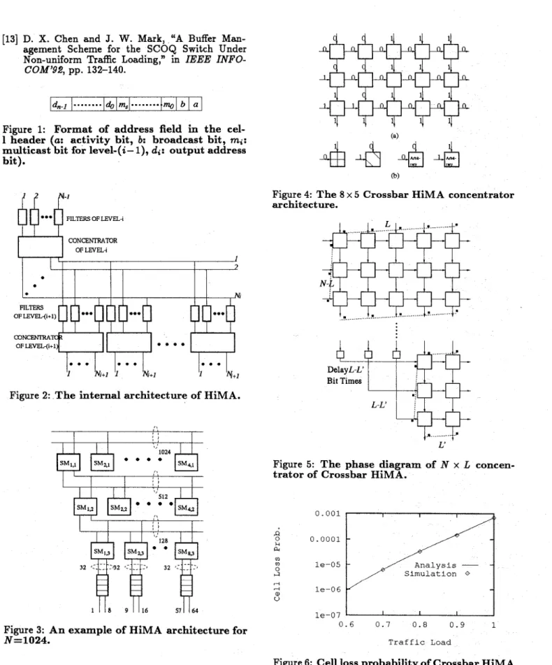
In order t o verify our analytical formulas, we con- sider the Crossbar HiMA with parameters: N=64, M1=2, M2=2, &=2, N1=42, N2=26, N3=16. Fig. 6 illustrates the cell loss probability of the proposed switch under uniform traffic for various traffic loads.
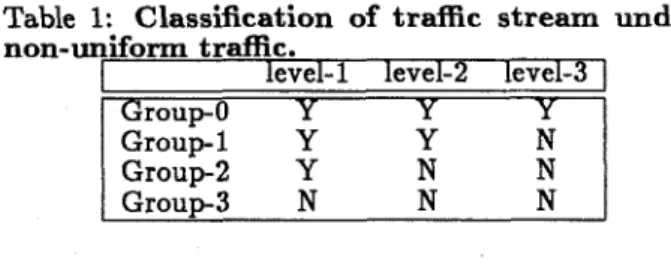
It indicates that the analysis technique presented in Sec. 3.1 yields very close numerical results to the sim- ulation statistics. To show the effect of non-uniform traffic, we divide the traffic streams carried by the switching modules at the last level of the proposed switch into four groups: Group-0-Group-3, as shown in Table 1. The entries in Table 1 indicate whether the
Table 1: Classification of traffic stream under non-uniform traffic.
level-1 level-2 level-3
Group-0 Y Y Y
G r o u p 1 Y Y N G ~ o u D - ~ Y N
N
1
GrouD-3 N N N Iheaviest traffic stream shares switching modules at the indicated level with the considered group. The G r o u p 0 is the most seriously affected and the G r o up3 expe- riences the smallest impact. With no loss of generali- ty, we select the output-1 as the hot-spot traffic des- tination output and the input-1 and output-1 as the point-tepoint traffic source-destination pair. Fig. 7 shows the results under the hot-spot traffic. The 95% confidence interval is also provided. Fig. 8 presents the corresponding results in the point-to-point condi- tion. These results convince us that the approxima, tion method presented in Sec. 3.2 and Sec. 3.3 leads t o
a worst case estimation of the actual cell loss proba- bility. Fig. 9-10 show the N=1024 case. These results verify again that HiMA can provide a very low cell loss probability even under the non-uniform traffic (if the buffer space is infinite).
5
Comparisons between HiMA and
In the practical implementation of an LATM switch, several factors can limit its development: to- tal complexity in the whole switch, the number of crosstalks which constricts the switching speed, the delay through the entire switch which dominates the delay time of network, the scalability to expand the switch size to accommodate the future usage, and thesynchronization problem. In fact, we can not make an accurate computation of the above parameters before practical chip design. To result in a n approximate and fair comparison of the above li,mitative factors between the proposed and the other switches, we assume the following.
1. As in [2], we estimate the complexity of a switch- ing element and a filter by 16 and 5 gates re- spectively, if each switching element’s switching
the other switches
function depends only on the activity bit of in- put cell’s header. When the switching function relies on more than one bit of the address field, there is no exact estimation of the complexity of each switching element. We assume that the ac- tual complexity of this element is approximately equal to n times of 16 gates, where n is the num- ber of bits for a switching element to work on. 2. In the estimation of crosstalk, it is impossible to
obtain the real value in the chip layout level. We consider only the cross points of the wires con- nected between switching elements in the entire switching network
.
3. To switch t o the correct direction, the switching element must collect enough information about the switching function before doing its own task. Here we approximate the delay through a switch- ing element working on n bits of information as n bit times long.
4. In the scalability comparison, we consider only those designs which can be easily expanded t o an arbitrary size without changing the switching network’s topology and disturbing existing con- nections t o be truly scalable in Table 2. Also, we decide that only those architectures which have insignificant difference in the distance of connec- tion wires between switching elements deserve a
“Y in the synchronization field of Table 2. 5. For the sake of simplicity, we only compare HiMA
with some other switch proposals which have mul- ticast and broadcast capabilities, due to the fact that these two capabilities a r e very important for LATM.
The comparison results are shown in Table 2. The common system parameters are: number of 1/0 port-
s = 1024, traffic load = 1.0, cell loss probability
5
In order to emphasize the superiority ofHiMA, we choose the largest dimension for a LATM switch, the lowest cell loss probability requirement in
a high speed LAN environment. In the Batcher Hi- MA row, we select the following parameters: M1=4, M2=4, M3=8, N1=512, N2=128, N3=32. In the Crossbar HiMA row, we set M1=8, M2=4, M3=4, N1=203, N2=74, N3=32. By the knockout principle, it is easy to prove that eight output ports per common output buffer (32 x 32) can retain cell loss probability lower than with infinite buffer space under arbi- trary t r a c pattern. From Table 2 w e can see that the Batcher HiMA is better than Crossbar HiMA in cost and delay time. But considering the high speed con- straint and the synchronization problem, the Crossbar HiMA seems more promising.
We then compare the Recursive Switch[3] with the Crossbar HiMA. It is evident that the proposed switch is superior to the Recursive Switch in complexity and delay columns. As described in Sec. 2.1, the Recur- sive Switch has more constraints than our proposed architecture in deciding the network parameters to
>le 2: Comparisons between HiMA and the ier switches.
crasstalk complex. Batcher 2 x 10⁷ 7.8 x log
HiMA
Crossbar 5.2 x lo6 2.9 x lo7
HiMA
Knockout 2.1 x lo9 2.0 x lo8 Switch [2]
Christmas 3.27 x l o 7 1.8 x l o 7
"Iee[5]
Recursive 2.84 x lo6 1.0 x los
Switch[3] SCOQ[4] 1.57 x lo7 5.16 x l o 6 Batcher 0.318 Y N Crossbar min = 2.74 Y Y Knockout 2.43 Y N Christmas 0.776 Y N Recursive max = 10.7 Y Y
delay scal. synch. HiMA HiMA m a x = 2.82 Switch Tree Switch SCOQ 1.325 N N
avoid the out-of-sequence problem. In these compar- isons, we select the best parameters to decrease the cost of the Recursive Switch, but the optimized Recur- rive Switch may not be able to avoid out-of-sequence
tit this moment. When one compares the Knockout
Switch and the Christmas Tree Switch with the Batch- er HiMA, the latter switch exhibits its excellent char- acteristic in all columns again.
From Table 2, we can make the comparisons be- tween the proposed switch and SCOQ. The results whow that the proposed switch's performance is close
to SCOQ. But SCOQ adopted the Batcher-banyan concept, so it is not easy to deal with the synchroniza- tion problem, especially in a high speed environment. At the same time, when SCOQ is going to expand to
IL larger size, the connection wires between the Batch-
er sorter and the banyan networks must be removed and relocated again to fit the expansion requirement. These two drawbacks can become the potential diffi- cdties for the practical application of SCOQ.
6
Conclusion
A high performance, space-division, near non- blocking LATM switch has been proposed. It employs partially shared output buffer to save the total buffer space. Its hierarchical and modular architecture can also be easily expanded to an arbitrary size. Its com-
mon bus topology makes it easy to implement both the multicast and broadcast functions. The cell loss analysis has been introduced and the numerical results
show that it can bear extreme non-uniform traffic. Its performance comparisons with others exhibit its ex- cellence in the future LATM switch implementation.
References
[l] Network Compatible ATM for Local Network Ap- plications, ver 1.01, Oct. 19, 1992.
[2] Y.
S.
Yeh, M. G. Hluchyj, and A.S.
Acampora, "The Knockout Switch: A Simple, Modular Ar- chitecture for Hi h-Performance Packet Switch- ing," IEEE J. SeB
ect. Areas Commun., vol. SAC-5, pp. 1274-1283, Oct. 1987.
[3] J. Chao, "A Recursive Modular Terabit/Second
ATM Switch," IEEE J. Select. Areas Commun.,
[4]
D.
X. Chen and J. W. Mark, "SCOQ: A FastPacket Switch with Shared Concentration and Output Queueing," in IEEE INFOCOM'Sl, pp.
[5] W. Wang and F. A. Tobagi, "The Christmas-Tree Switch: An Output Queueing Space-Division Fast Packet Switch Based on Interleaving Distri- bution and Concentration Functions," in IEEE
[6] P. Barri and J. A. 0. Goubert, "Implementation of a 16 to 16 Switching Element for ATM Ex- changes," IEEE J. Select. Areas Commun., vol.
9, pp. 751-757, June 1991.
[7] A. Itoh, et al., "Practical Implementation and Packaging Technologies for a Large-scale ATM Switching System," IEEE J. Select. Areas Com-
mun., vol. 9, pp. 1280-1288, Oct. 1991.
[8] T. C. Banwell, et al., "Physical Design Issues for Very Large ATM Switching System," IEEE J. Se-
lect. Areas Commun., vol. 9, pp. 1227-1238, Oct.
1991.
[9] T. Kozaki, et al., "32 x 32 Shared Buffer Type ATM Switch VLSI's for B-ISDN's," IEEE J. Se-
lect. Areas Commun., vol. 9, pp. 1239-1247, Oct.
1991.
[lo] J .
N.
Giacopell, e t al., "Sunshine: A High- Performance Self-Routing Broadband Packet Switch Architecture," IEEE J. Select. AreasCommun., vol. 9, pp. 1289-1298, Oct. 1991.
[ll] F. A. Tobagi, T. Kwok, and F. M. Chiussi, "Ar- chitecture, Performance, and Implementation of the Tandem Banyan Fast Packet Switch," IEEE J. Select. Areas Commun., vol. 9, pp. 1173-1192, Oct. 1991.
[12] M. G. Hluchyj and M. J. Karol, "Queueing in
High-Performance Packet Switching," IEEE J. S-
elect. Areas Commun., vol. 6, pp. 1587-1597, Dec.
1988.
vol. 9, pp. 1161-1172, Oct. 1991.
145-154.
[13]
D. X.
Chen and J. W. Mark, “A BufferMan-
agement Scheme for the SCOQ Switch Under Non-uniform Traffic Loading,” in IEEE INFO-COM’92, pp. 132-140.
Figure 1: Format of address field in the cel- l header (a: activity bit, b: broadcast bit, mi:
multicast bit for level-(a- l), di: output address bit). CONCENTRATOR FILTERS . . e OF LEVEL++l)
Figure 2: The internal architecture of HiMA.
I I I< , , I
1
P,
Figure 3: An example of HiMA architecture for
N=1024.
(a)
(b)
Figure 4: The 8 x 5 Crossbar HiMA concentrator architecture. ..= ... Delay L-L' Bit Times L-L‘ I
w
J ... L’ JFigure 5: The phase diagram of
N
x L concen- trator of Crossbar HiMA.m m 0 ;I 4 (U V 0.001 0.0001 le-05 le-06 l e - 0 7 0 . 6 0 . 7 0 . 8 0 . 9 1 T r a f f i c Load
Figure 6: Cell loss probability of Crossbar HiMA versus mean traffic load p under uniform traffic; number of input/output ports N
=
64.Ana. of broup-0 .L--
Sim. of Group-0 m-i
Ana. of GrouD-1
-
0.1 0.01 0.001 0.0001 h i m . of Groub-1 k 0 - i _I Ana. of Group-2 S i m . of Group-2 m-i -. Ana. of Group-3-
- S h . Of Group-3*
le-05 0 0 . 0 2 0.04 0.06 0 . 0 8 0.1 Concentration FactorFigure 7: Cell loss probability of Crossbar Hi- MA versus concentration factor h under hot- spot traffic for various groups; number of in-
put/output ports
N
=
64, mean traffic load p=
0.9. 0.0005 I Ana. of G~ouD-O 1 0.0003 0.0002 Ana. or Group-2 s i m . or Group-2 e-i , Ana. of Group-3 *- _-.- S i m . of Group-) m-! _/- Ana. or total -.-.- -.I -!2 0.0001 8 ' I 0 0.1 0 . 2 0 . 3 0 . 4 0 . 5 0 . 6 0 . 7 0.8 0 . 9 Non-unironn DegreeFigure 8: Cell loss probability of Crossbar Hi- MA versus non-uniform degree ( under point- tcbpoint traffic for various groups; number of biput/output ports
N
=
64, mean traffic loadp
=
0.9. 4 4:
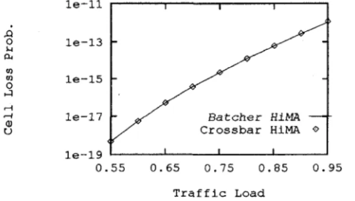
le-11 I I I I 1 le-13 le-15 l e - 1 7 l e - 1 91
1 I I 1 0 . 5 5 0 . 6 5 0 . 7 5 0 . 8 5 0 . 9 5 T r a f f i c Load le-11 a G r o u p - 0 -4- 0 G r o u p - 1 -Ef- VI VI l e - 1 2 0 ri ri a, U le-13 0 . 1 0 . 2 0 . 3 0 . 4 0 . 5 0 . 6 0 . 7 0 . 8 0 . 9 N o n - u n i f o r m DegreeFigure 10: Mean cell loss probability of Cross- bar HiMA versus non-uniform degree ( under point-to-point traffic for various groups; num- ber of input/output ports
N
=
1024, mean traf- fic load p=
0.9.Figure 9: Mean cell loss probability of HiMA versus mean traffic load p under uniform traffic; number of input/output ports