Adaptive Recovery Techniques for Real-Time
Audio Streams
Wen-Tsai Liao, Jeng-Chun Chen
†, and Ming-Syan Chen
Electrical Engineering Department
National Taiwan University
Taipei, Taiwan, ROC
Philips Research East Asia - Taipei
†Taipei, Taiwan, ROC
Email: {[email protected], [email protected], [email protected]}
Abstract— There are a number of packet-loss recovery techniques
pro-posed for streaming audio applications recently. However, there are few works that are able to exploit the tradeoff between the recovery quality and the computational complexity. In this paper, we develop a recovery method, called DSPWR (Double Sided Pitch Waveform Replication) which is able to tolerate a much higher packet loss rate. In essence, DSPWR is composed of several procedures devised to improve the quality of the reconstructed speech. It is noted that a more sophisticated recovery scheme that can toler-ate a higher degree of packet loss in general requires a larger computational cost. In view of this, we evaluate the quality of the reconstructed speech un-der different packet loss rates for various receiver-based recovery methods, and compare the computational complexity among these methods. Under the acceptable speech quality whose MOS (Mean Opinion Score) is above 3.5, we develop an adaptive mechanism that can select the recovery method with the minimal complexity in accordance with different packet loss rates encountered. To conduct real experiments in the networks, we implement these recovery methods and evaluate the performance of DSPWR devised and the adaptive recovery techniques empirically. As validated by our ex-perimental results, the adaptive mechanism is able to strike a compromise between the computational overhead and the quality of the speech desired.
I. INTRODUCTION
Due to the fast growth of Internet, there are an increasing number of important applications being developed on it. Among others, the streaming of real-time audio is one of the most im-portant applications. The use of real-time audio includes voice conference, distance learning, and Internet telephony, etc. How-ever, due to the unreliable characteristics of a packet-switched network, packets might get lost or arrive late at the receiver for playing during the transmission over the network. Such packet loss will cause speech signal dropped out which will in turn re-sult in producing sound of poor quality. Hence, how to recover the lost packets and alleviate the above mentioned problem has been deemed a very important issue for packet voice communi-cation.
There have been many different recovery techniques pro-posed, and recent surveys can be found in [1] and [2]. These techniques can be divided into two classes, i.e., sender-based (e.g., [3], [4], [5], [6], [7], [8], [9] et al.) and receiver-based (e.g., [10], [11], [12], [13], [14], [15] et al.). These recovery techniques are basically designed to improve the quality of the reconstructed speech in the presence of packet loss, and to en-able the packet voice communication to be toleren-able to higher packet loss rates. To achieve this goal, one has to take packet overhead, delays, and computational complexity into consider-ation. The overhead here means the redundancy in packets, the
delay refers to the look ahead delay, and the computational com-plexity means the processing delay introduced by computation. Clearly, it would be perfect, but unlikely in practice, to have one technique that can be tolerable to high packet loss rates with overhead, delay and complexity minimized.
In this paper, we focus on the receiver-based recovery meth-ods in that they do not introduce extra packet overhead and are independent of the techniques taken by the sender. Note that sender-based recovery methods usually need more processing delay and look ahead delay, and cannot recover all kinds of the packet loss [2], [16]. We would like to exploit the tradeoff be-tween the speech quality and the computational complexity for receiver-based recovery methods. In practice, it is usually not desirable to improve the quality of a recovery method at the cost of very high complexity. In other word, it is of practical importance to devise the recovery method that can achieve the required quality of reconstructed speech with the minimal com-plexity. In this paper, we develop a recovery method, called DSPWR (Double Sided Pitch Waveform Replication) which is able to tolerate a much higher packet loss rate. It is noted that a more sophisticated recovery scheme that can tolerate a higher degree of packet loss in general requires a larger computational cost. In view of this, we evaluate the quality of the reconstructed speech under different packet loss rates for various kinds of receiver-based recovery methods, and compare the computa-tional complexity among these methods. Same as in [11] [12], MOS (Mean Opinion Score) is used as a measurement in our experiments. Under the acceptable speech quality whose MOS is above 3.5 (when 5 represents the highest score), we develop an adaptive mechanism that can select the recovery method with the minimal complexity in accordance with different packet loss rates encountered, thereby striking a compromise between the computational complexity and the quality of the speech desired. Specifically, we propose in this paper an improved version of the pitch waveform replication recovery method called DSPWR (standing for Double Sided Pitch Waveform Replication). Also, several procedures are devised to improve the quality of the re-constructed speech. First, we propose a procedure PSA (stand-ing for Pitch Segment Adjustment) to adjust the pitch period segments used to recover the lost packet. The procedure PSA
considers the amplitude continuity for the boundaries between the duplicated pitch segments used to recover the lost packet. Second, we propose a procedure PMP (standing for Phase Matching using Pitch) to decide how to reconstruct the lost packet by using the two pitch segments on both sides of the lost packet. The procedure PMP is designed to minimize the phase discontinuity caused by the difference between the two pitch pe-riod segments on both sides of the lost packet. Third, we pro-pose procedures FWAA (standing for ForWard Amplitude justment) and BWAA (standing for BackWard Amplitude Ad-justment) to adjust the amplitude of the reconstructed packet. Procedures FWAA and BWAA are designed to make the am-plitude of the reconstructed packet continuous to its neighbor-ing packets. With the above procedures developed, algorithm DSPWR is devised by first using the pitch detection algorithm to estimate the pitches of the two packets preceding and fol-lowing the lost packet, and then according to the pitch estima-tion results, explicitly considering the four possible cases in the presence of packet loss, i.e., (1) both packets are voiced (using scheme BV), (2) the preceding one is voiced (using scheme PV), (3) the following one is voiced (using scheme FV), and (4) both are unvoiced (using scheme BU).
In the first case, we propose a scheme BV (standing for Both packets Voiced) to reconstruct the lost packet when both of the two packets preceding and following the lost packet are voiced. It is noted that the approach of using both pitch segments on both sides of the lost packet to reconstruct the lost packet in scheme BV will lead to better results than the one of only using the preceding pitch segment in the pitch waveform replication (PWR) method. The scheme BV improves the quality of the re-constructed speech by using the procedures PSA, PMP, FWAA and BWAA mentioned above. For the second case, we propose a scheme PV (standing for the Previous packet Voiced) to re-construct the lost packet when only the packet preceding the lost packet is voiced. For the third case, we present a scheme FV (standing for the Future packet Voiced) to reconstruct the lost packet when only the packet following the lost packet is voiced. It is observed that to reconstruct the lost packet by us-ing the pitch segment of the packet followus-ing the lost packet adopted by scheme FV outperforms the alternative of using the repetition method. For the last case, we propose a scheme called BU (standing for Both packets Unvoiced) to reconstruct the lost packet when both of the packets near the lost packet are un-voiced. The scheme BU is designed to reduce the problem caused by using repetition method when there are a transition from voiced to unvoiced in the preceding packet, and also a transition from unvoiced to voiced in the following packet. The scheme BU reconstructs the lost packet by using the rear half of the preceding packet to recover the first half of the lost packet and using the first half of the following packet to recover the rear half of the lost packet. In essence, algorithm DSPWR is com-posed of the above four schemes and utilizes them to handle the
respective situations.
Clearly, different methods involve different computational overhead. Though having a much higher tolerance to packet loss, algorithm DSPWR unavoidably incurs a larger computa-tional cost. Naturally, one would like to adopt a proper recovery scheme in response to the packet loss rate, while attaining the required speech quality and minimizing the corresponding cost. Hence, we evaluate the performance of several recovery meth-ods for packet loss rates ranging from 1% to 30%, and compare the complexity among these methods. Specifically, we use the repetition method, the PWR method and the DSPWR method as the members of the adaptive recovery techniques, and de-rive a system model for the adaptive recovery mechanism. We define the packet loss period as the period from previous lost packet to the current lost packet and use it as the measurement of the packet loss rate. We introduce two parameters to eval-uate the current packet loss rate: (1) the transient packet loss period, which is the most recent packet loss period, and (2) the average packet loss period, which is the mean of the most re-cent five packet loss periods. Explicitly, we consider the packet loss period distribution first. If the transient packet loss period is larger than 100 packets, meaning that the noise made by current lost packet is hard to perceive, using a simple recovery method, i.e., the repetition method, will suffice. On the other hand, if the transient packet loss period is small than 5 packets, meaning that the noise could be very noticeable, we will use the sophis-ticated recovery method, i.e., the DSPWR method, in order to achieve the speech quality required. If the above two conditions do not apply, meaning that the transient packet loss period is between 5 packets and 100 packets, we shall just consider the effect of packet loss rate to reconstruct speech quality. We im-plement these recovery methods and evaluate the performance of DSPWR devised and the adaptive recovery techniques em-pirically. As validated by our experimental results, the adaptive mechanism is able to strike a compromise between the compu-tational overhead and the quality of the speech desired.
This paper is organized as follows. Related techniques on speech recovery are described in Section II. The algorithm DSPWR (double sided pitch waveform replication) is developed in Section III. Experimental results are presented in Section VI. This paper concludes with Section V.
II. RELATEDRECOVERYAPPROACHES
To derive the mechanism that can adaptively choose a proper recovery method under various packet loss rates, we survey sev-eral speech recovery methods in this section.
A. Silence Substitution
The silence substitution method just fills the lost packet with silence (i.e., zero) to maintain the speech timing sequence. The complexity is very low and this method is thus frequently used. In our experiments, the packet loss rate tolerable by this method
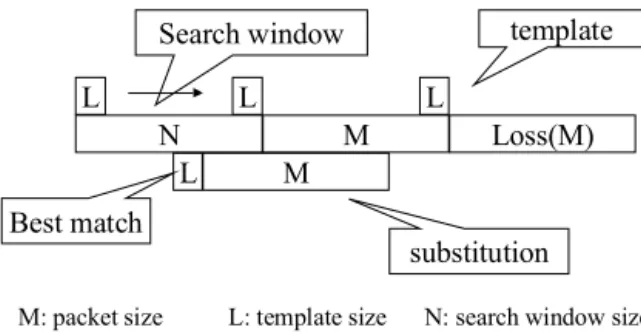
M L L L Loss(M) L N template M Search window Best match substitution M: packet size L: template size N: search window size
Fig. 1. Illustration of one-sided pattern matching method.
can be up to 2 %.
B. Repetition
The repetition method uses the packet preceding to the lost packet as the substitution. Its complexity is also close to zero, same as that of the silence substitution method. However, the repetition method has better recovery performance than the si-lence substitution method. In our experiments, the reconstructed speech using this method can tolerate a packet loss rate of up to 4%.
C. Pattern Matching
The pattern matching method is proposed in [10] [11]. Figure 1 illustrates how the one-sided pattern matching method works. The algorithm searches previous packets to find a packet that most resembles the missing one. It uses a segment of the L samples just before the missing packet as a template. Then, the pattern matching method starts to scan a search window contain-ing N samples to search for the candidate segment containcontain-ing L samples that best matches the template. The matching criterion is the minimal normalized absolute difference between the tem-plate and the candidate segment. After the scan is finished, we use the packet containing M samples that immediately follow the best matched L samples to substitute for the lost one. The amplitude of the substitution packet is multiplied by the ratio of the average amplitude of the template to that of the candidate segment, to improve the reconstructed speech quality. The two-sided pattern matching method works similarly to the one-two-sided method. According to the evaluation results in [10], for the one-sided pattern matching scheme, independent of the packet size, a search window duration of 16 ms and a template size of 4 ms are good choices. On the other hand, for two-sided pattern match-ing scheme, a search window duration of 8 ms and a template size of 2 ms should be used independent of the packet size. This method will, however, cause an uncomfortable clipping noise if there is a transition from unvoiced to voiced speech during the recovery. According to our experiments, the complexity of pattern matching is much higher than that of the previous two methods by one to two orders of magnitude. The corresponding packet loss rate tolerable is up to 6%.
Max = X(i) position = i Count= Hold X(i) > MAX?
factor = decreasing factor Count = Hold Max = X(0) i < size ? Store position Max *= factor End < 0 = 0 > 0 Yes Yes No i++ --Count
Fig. 2. Illustration of the positive peak detector.
D. Pitch Waveform Replication
The pitch waveform replication method uses two parallel de-tectors which continually detect the positive and negative peaks of the speech, respectively, to estimate the pitch of the packet before the lost one [10][11]. We illustrate how the positive peak detector works in Figure 2. In Figure 2, assume the speech sig-nal is x[n]. The positive peak detector updates the value of MAX with successive local maxima of speech samples until no update has occurred for the number of Hold samples. Then, MAX de-cays exponentially by a factor (i.e., the value of the decreasing
factor is smaller than one) until it is exceeded by a speech
sam-ple. The negative peak detector works analoguely. From the two peak detectors, we can obtain the four time intervals that separate the most recent three maxima and minima respectively. By using these four pitch estimations, PWR can decide whether the speech before the missing packet is voiced. If the speech is not voiced or the pitch detection fails, PWR uses the repetition method to recover the lost packet. If the speech is voiced, PWR reconstructs the missing packet by duplicating the pitch period sample preceding the missing packet throughout the region of the lost packet. The complexity of this method is lower than that of the pattern matching method, but the quality of the re-constructed speech is better than that of pattern matching. The packet loss rate tolerable is up to about 10%.
In addition to the recovery methods described above, there are several different recovery methods. Since most of these methods tend to suffer either long delay or high computational complex-ity, those methods do not appear to be suitable for our applica-tion requirement of being interactive and receiver-based. Nev-ertheless, the mechanism of this adaptive scheme can be easily modified if some more recovery schemes are derived and to be included into it.
III. DOUBLESIDEDPWR
After the description of the recovery methods, we propose an improved version of the PWR method, called DSPWR (double sided pitch waveform replication), to alleviate the shortcomings of the PWR method as to be pointed out in Section III.A below. The motivation of designing DSPWR is described in Section III.A. Section III.B presents the design of some procedures in DSPWR. The structure of DSPWR is given in Section III.C.
A. Motivation
Note that there are three important factors that affect the speech quality, namely amplitude continuity, phase continuity and frequency continuity. Explicitly, the amplitudes, phases and frequencies have to be continuous at the boundaries between the substitution packets and their neighboring packets (includ-ing the previous and subsequent packets received), otherwise audible noise will occur. It is noted that the PWR method has two shortcomings. First, PWR only copes with the continuity for the boundaries between the reconstructed packets and their previous packets when the speech is voiced, whereas the conti-nuity for the boundaries between the reconstructed packets and the subsequent ones is not properly dealt with. This is referred to as the discontinuity problem of PWR. The second shortcom-ing of the PWR method is that it uses the repetition method to recover the lost packet when the speech is unvoiced or when the pitch detection fails. However, the reconstructed speech will not have acceptable quality when there is a transition from voiced to unvoiced at the substitution packets. This is referred to as the repetition problem of PWR. It is noted that there are some recon-struction techniques, such as the phase-matching reconrecon-struction method [13] and the double sided periodic substitution method [12], proposed to solve the first problem of PWR on disconti-nuity. However, the phase-matching method tends to introduce extra frequency discontinuity, and as a result there is still audi-ble noise. The douaudi-ble sided periodic substitution method does not take the phase discontinuity into consideration. Neither the phase-matching method nor the double sided periodic substitu-tion method addressed the second problem of PWR on repetisubstitu-tion mentioned above. Consequently, we propose in this paper a re-covery method, called DSPWR (double sided pitch waveform replication), to remedy the above mentioned problems.
B. Design of DSPWR
For the problem of discontinuity, as will be explained in de-tails below, we devise specific procedures to deal with pitch seg-ment adjustseg-ment, phase discontinuity and amplitude adjustseg-ment. For ease of exposition, the packet immediately preceding spectively, following) the lost packet is called the preceding (re-spectively, following) packet. To address the problem of PWR on repetition, instead of using the ordinary repetition method, we use the rear half segment of the preceding packet and the first half segment of the following packet to recover the lost packet.
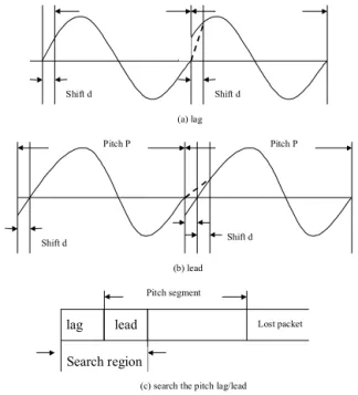
Shift d Shift d
Pitch P Pitch P
Shift d Shift d
(a) lag
(b) lead
(c) search the pitch lag/lead
lag lead Lost packet
Pitch segment
Search region
Fig. 3. Procedure PSA for the preceding packet, making an amplitude adjust-ment to the pitch (P) period segadjust-ment: (a) the pitch lagging condition, (b) the pitch leading condition, (c) the searching procedure for the value of lag-ging/leading.
This scheme is easy to implement and is found to be effective to reduce the noise caused by the transition from voiced to un-voiced, and vice versa.
B.1 Pitch segment adjustment
First, we consider the amplitude continuity for the boundaries between the reconstructed pitch segments used to recover the lost packet. Note that in the PWR method there may be am-plitude discontinuity between the head and tail of the pitch seg-ment. The procedure of pitch amplitude adjustment (abbreviated as PSA), depicted in Figure 3, is derived to solve this problem. Due to its frequent occurrences, this problem is as important as the one caused by the phase discontinuity. The procedure of PSA is described below.
Procedure PSA: /* Procedure for the adjustment of pitch
seg-ment. Assume that the packet size is n, the pitch is P , and the speech signal is x[n]. */
Step 1. Search the region from x[n−1−P −3] to x[n−1−P +3] to find the sample x[n − 1 − P − 3 + i] whose value is the most close to that of x[n − 1];
Step 2. if (i <= 3) /∗ the amount of lagging: d = 3 − i ∗ / d = 3 − i;
else /∗ the amount of leading: d = i − 3 ∗ / d = 2 ∗ (i − 3);
Step 3. diff = x[n−P +d]−x[n−1]
d+1 ;
f or(j = 1; j <= d; j + +)
B.2 Dealing with phase discontinuity
We next consider the problem of phase discontinuity for the PWR method. As the scheme proposed in phase-matching method [13], we compute the phase of the beginning sample of the packet following the lost packet. However, instead of com-pressing or stretching the reconstructed packet as in [13], we employ a different approach to deal with the phase discontinu-ity. We use both of the pitch segments to reconstruct the lost packet, and use the pitch difference between the pitches com-puted from both sides of the lost packet to eliminate the phase difference. Suppose that the pitch of the preceding packet is P P, the pitch of the following packet is P F , the size of packet is n, the phase of the beginning sample of the following packet is phase, the number of pitch segments of the preceding packet used to reconstruct the lost packet is a, the number of pitch seg-ments of the following packet used to reconstruct the lost packet is b, and the number of remaining samples after the fill-up with the pitch segments is c. Then, we reconstruct the lost packet as illustrated in Figure 4. From Figure 4, we can derive the follow-ing equations.
a ∗ P P + b ∗ P F + c = n;
→ (a + b) ∗ P P + b ∗ (P F − P P ) + c = n; → b ∗ (P F − P P ) + c = n − (a + b) ∗ P P ; → b ∗ (P F − P P ) + c = n mod P P + k ∗ P P.
To erase the phase discontinuity, c has to be equal to phase. Replacing c with phase in the above equation, we obtain the following equation.
b ∗ (P F − P P ) + phase = n mod P P + k ∗ P P ; → b ∗ (P F − P P ) = n mod P P − phase + k ∗ pp; → b ∗ pitch_difference = phase_difference.
Using the above equation, we can derive the parameters a, b and c which can then be used to reconstruct the lost packet by procedure PMP as below.
Procedure PMP: /* Procedure for phase matching using pitch
difference */ Step 1. a =¥ n P P ¦ ; b = 0; c = n mod P P ;
phase_diff = c − phase; pitch_diff = P F − P P;
Step 2. if(phase_diff ∗ pitch_diff == 0) f inish / ∗ one − sided ∗ /
Step 3. else if(phase_diff ∗ pitch_diff > 0){ / ∗ have the same sign ∗ /
b = round(phase_dif fpitch_diff ) <= a − 1 ? round(phase_diffpitch_diff ) : a − 1;
a = a − b;
c = c − b ∗ pitch_diff;
a segments b segments
PP PP c PF PF
Fig. 4. Illustration of procedure PMP. The lost packet is reconstructed by using the pitch segments of the packet at both sides of the lost packet.
if (P P − abs(phase_diff) < abs(c − phase)){ a =¥ n P P ¦ ; b = 0; c = n mod P P ; } Step 4. else if(phase_diff > 0){ / ∗ pitch_diff < 0 ∗ /
phase_diff = phase_diff − PP; goto Step 3; }
Step 5. else / ∗ pitch_diff > 0, phase_diff < 0 ∗ /{ phase_diff = phase_diff + P P goto Step 3}
B.3 Dealing with amplitude adjustment
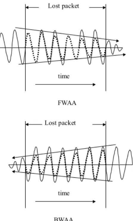
Finally, we adjust the amplitude of the reconstructed packet in such a way that the amplitude is continuous inside the packet as well as to the neighboring packets. Two amplitude adjust-ment procedures, i.e., one using the preceding pitch segadjust-ment, called FWAA (standing for forward amplitude adjustment) and the other using the subsequent pitch segment, BWAA (stand-ing for backward amplitude adjustment), are described below. Assume that the amplitude of the previous segment is AP , the amplitude of the future segment is AF , the packet size is n and the signal segment required to adjust is from x[start] to x[end] in the reconstructed packet. The corresponding scenarios are given in Figure 5.
Procedure FWAA: /* Procedure for amplitude adjustment in a
forward manner. */
Step 1. factor = (AF−AP ) (AP∗n) .
Step 2. for(i = start; i <= end; i + +) x[n]∗ = 1 + factor ∗ i.
Procedure BWAA: /* Procedure for amplitude adjustment in a
backward manner. */ Step 1. factor = (AP−AF )
(AF∗n) .
Step 2. for(i = start; i <= end; i + +) x[n]∗ = 1 + factor ∗ (n − i).
C. Structure of DSPWR
With the above procedures developed, the structure of DSPWR recovery method proposed is described below. First,
FWAA Lost packet Lost packet BWAA time time
Fig. 5. Illustration of the procedure FWAA and BWAA, where the dotted lines represent the waveforms after reconstruction.
Scheme BV
Scheme PV
Both success Both fail
Pitch detection on both sides of the lost packet
Pitch detection 1. Procedure PSA 2. Compute amplitude 3. Compute Phase 4. Procedure PMP 5. Reconstruct the lost
packet 6. Procedure FWAA
and BWAA
1. Procedure PSA 2. Compute amplitude 3. Reconstruct the lost
packet 4. Procedure FWAA 1.Reconstruct the lost packet 1. Procedure PSA 2. Compute amplitude 3. Reconstruct the lost
packet 4. Procedure BWAA Scheme BU Scheme FV Fig. 6. Structure of DSPWR.
we use the pitch detection algorithm in the PWR method to esti-mate the pitches of the packets preceding and following the lost packet. Then, according to the pitch estimation results, we have different processing schemes as illustrated in Figure 6.
Algorithm DSPWR /*Algorithm for the double sided pitch
waveform replication method */
Step 1. Employ the pitch detection algorithm proposed in the PWR method [10] to estimate the pitches of the packets preced-ing and followpreced-ing the lost packet.
Step 2. If both estimations succeed (i.e., are voiced), we use the scheme BV to recover the lost packet.
Step 3. If only the preceding one succeeds (i.e., is voiced), we use the scheme PV to recover the lost packet.
Step 4. If only the following one succeeds, we use the scheme FV to recover the lost packet.
Step 5. If both estimations fail, we use the scheme BU to recover the lost packet.
If the pitch estimations on both sides are successful, we use both of the previous pitch (P P ) period sample segment and the future pitch (P F ) period sample segment to reconstruct the lost packet. First, we adjust both pitch segments by using the proce-dure PSA as illustrated in Figure 3 and calculate the peak am-plitudes of these pitch segments. Then, we use the algorithm proposed in the phase-matching recovery method to derive the phase of the beginning sample of the packet following the lost packet. Using the procedure PMP to derive the parameter a, b, and c, we can reconstruct the lost packet by having a repeti-tions of the preceding pitch segment (P P ), b repetirepeti-tions of the following pitch segments (P F ), and the first c samples of the preceding pitch segment. Finally, we adjust the amplitude of the whole reconstructed lost packet using procedure FWAA and procedure BWAA. Scheme BV is outlined below.
Scheme BV: /* For the case that both packets are voiced.
As-sume that the pitch estimated from the preceding packet is P P and the pitch estimated from the following packet is P F . */ Step 1. Use the procedure PSA to adjust the P P period segment just preceding the lost packet and the P F period segment just following the lost packet.
Step 2. Compute the peak amplitude of the P P period segment just preceding the lost packet and denote this amplitude as AP . Also, compute the peak amplitude of the P F period segment just following the lost packet and denote this amplitude as AF . Step 3. Compute the phase of the beginning sample of the packet following the lost packet by the algorithm proposed in the phase-matching recovery method.
Step 4. Use procedure PMP to derive the parameters a, b and c. Step 5. Copy a repetitions of the preceding pitch segment into the lost packet.
Step 6. Then copy the first c samples of the preceding pitch seg-ment into the lost packet.
Step 7. Copy b repetitions of the following pitch segment into the lost packet.
Step 8. Use procedure FWAA to adjust the amplitude of the leading pitch segment in the lost packet.
Step 9. Use procedure BWAA to adjust the amplitude of the rear pitch segment in the lost packet.
If just one side of the pitch estimation is successful, we will use the successful side to reconstruct the lost packet. We as-sume that the pitch successfully estimated is P . First, we adjust the pitch segment consisting of P samples just preceding or fol-lowing the lost packet by using the procedure PSA as depicted in Figure 3 and calculate the peak amplitudes of this pitch seg-ment. Then, we reconstruct the missing packet by duplicating this pitch segment throughout the region of the lost packet. In addition, we adjust the amplitude of the reconstructed speech by
using the procedure FWAA or BWAA to make the amplitude lin-early decrease from the voiced side to the other side. Note that according to our experiments, we do not need to consider the phase discontinuity from a voiced speech to unvoiced speech, since the energy of unvoiced speech is in general so small and barely audible. Schemes PV and FV are outlined below.
Scheme PV: /* For the case that the preceding packet is voiced.
Assume that the pitch estimated from the preceding packet is P . */
Step 1. Adjust the P period segment just preceding the lost packet by using the procedure PSA.
Step 2. Compute the peak amplitude of the P period segment just preceding and following the lost packet.
Step 3. Repeat the preceding segments throughout the region of the lost packet as the substitution.
Step 4. Adjust the amplitude of the substitution using procedure FWAA.
Scheme FV: /* For the case that the following packet is voiced.
Assume that the pitch estimated from the following packet is P. */
Step 1. Adjust the P period segment just following the lost packet by using the procedure PSA.
Step 2. Compute the peak amplitude of the P period segment just preceding and following the lost packet.
Step 3. Repeat the following segments throughout the region of the lost packet as the substitution.
Step 4. Adjust the amplitude of the substitution using procedure BWAA.
If the pitch estimations on both sides failed, we reconstruct the lost packet by the rear half packet of the preceding packet and the first half packet of the following packet. This method is easy to implement and found to be effective to reduce the noise caused by the transition from voiced to unvoiced and vice versa. The scheme is presented as follows.
Scheme BU /* For the case that both packet are unvoiced.*/
Step 1. Copy the rear half of the preceding packet into the region of the first half of the lost packet.
Step 2. Copy the first half of the following packet into the region of the rear half of the lost packet.
IV. ADAPTIVERECOVERYTECHNIQUES
Clearly, different recovery methods involve different compu-tational overhead. As will be shown in our experimental re-sults later, though having a much higher tolerance to packet loss, algorithm DSPWR unavoidably incurs a larger computa-tional cost. In view of this, one would like to adopt a proper recovery scheme in response to the packet loss rate, while at-taining the required speech quality and minimizing the corre-sponding cost. Consequently, we deal with the development of
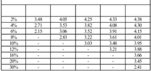
2% 3.48 4.05 4.25 4.33 4.38 4% 2.71 3.53 3.82 4.08 4.30 6% 2.15 3.06 3.52 3.91 4.15 8% - 2.83 3.22 3.61 4.01 10% - - 3.03 3.48 3.95 12% - - - 3.21 3.88 16% - - - - 3.66 20% - - - - 3.45 30% - - - - 2.41
Fig. 7. The quality of several kinds of recovery methods under different packet loss rates.
Silence Repetition MatchingPattern PWR DSPWR 1500-2000 Complexity measured by processing time 1 1.5-2 750-1000 25-50 450-600
Fig. 8. The comparison of the complexity for different recovery methods (nor-malized by the time for the silence method).
the adaptive mechanism in this section. First, we analyze the re-constructed speech quality for various recovery methods under different packet loss rates, and compare the computational over-head among these methods. Specifically, we propose a system model to realize which recovery method should be used subject to a given packet loss rate. According to the system model, we are able to adaptively select the most adequate recovery method that incurs the minimal computational overhead and possesses the required speech quality.
A. Selection of Recovery Methods
We use the rate of 8 K/s as our speech sampling rate, 16 bit PCM as our speech samples, and 128 samples as the packet size. The source materials for the subjective test (MOS) consist of one male and one female speakers, each of whom spoke for 12 seconds. The subjective quality test scores under various packet loss rates for different recovery methods are shown in Figure 7. The complexity is computed by utilizing the profile results provided by VC++ [17]. The comparison results are shown in Figure 8.
In our experiments, it can be seen that when the packet loss rate is below 4%, the repetition method is the best choice among all methods due to its close-to-zero complexity, close-to-zero delay and acceptable quality. The silence method is not adopted since its reconstructed speech quality is worse than that of the repetition method. When the packet loss rate is between 4% and 10%, the PWR method is the one to use. The pattern matching method is not used for its worse quality and higher complexity than those of the PWR method. When the packet loss rate goes over 10%, we can only use the DSPWR method to attain the quality required.
B. Building a System Model
Next, we set up a system model which can be used to adap-tively select the recovery method according to the results in Fig-ure 7 and FigFig-ure 8. The packet loss period means the period from the previous lost packet to the current lost packet [16]. It can be calculated by subtracting the sequence number of the pre-vious lost packet from the sequence number of the current lost packet. Obviously, the packet loss period is the inverse of the packet loss rate. We use the packet loss period as the measure-ment of the packet loss rate for two reasons. First, by doing this, one only has to calculate the packet loss rate when any packet is lost, meaning that no extra computation is involved during the normal situation. Second, note that not only the packet loss rate but also the distribution of the lost packets will affect the reconstructed speech quality (especially the case of consecutive packet losses, which some recovery techniques are proposed to deal with, e.g., [18]) . We can easily take the distribution of packet loss period into consideration by using the packet loss packet period as the measurement.
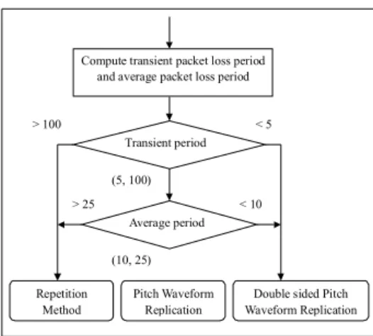
We introduce two parameters of the packet loss period to eval-uate the current packet loss rate, and use their values to decide which recovery method we shall utilize. The first parameter is the transient packet loss period, which is used to capture the packet loss period distribution. This value is calculated as the most recent packet loss period (the period between the current lost packet and the previous one). The second parameter is the average of the packet loss periods, which corresponds to the packet loss rate. This value is calculated as the mean of the most recent five packet loss periods. We consider the packet loss period distribution first. As illustrated in Figure 9, if the transient packet loss rate is very small (with a long packet loss period which is about 100 packets), the noise made by current lost packet is almost negligible. We shall thus employ the simple recovery method, i.e., the repetition method, for this case. On the other hand, if the transient packet loss rate is very high (with a short packet loss period which is about 5 packets), the noise is very noticeable, in which case the most sophisticated recovery method, i.e., the DSPWR method, is called for. Otherwise, when the transient period is of medium values, i.e., between 5 packets and 100 packets, we just consider the effect of packet loss rate to reconstruct speech quality. The recovery method is decided by choosing the one with minimal complexity and the required speech quality. Specifically, according to our results, when the average packet loss period is larger than 25 packets, we will use the repetition method. When the average packet loss period is between 10 packets and 25 packets, the PWR method is used. When the average packet loss period is smaller than 10 packets, the DSPWR method is employed.
C. Experimental Results
Using mathematical models, we can obtain the percentage of the computational cost saved as a function of the packet loss
> 25
> 100 < 5
< 10 Compute transient packet loss period and average packet loss period
Repetition Method Transient period Average period (5, 100) Pitch Waveform Replication
Double sided Pitch Waveform Replication (10, 25)
Fig. 9. Illustration of the system model for the adaptive recovery techniques.
rate. Assume that the packet loss period is x and the probability function of packet loss period is P rob(x). In addition, we rep-resent x1as the most recent packet loss period, x2as the second
to the most recent packet loss period. xi is defined analoguely.
Then, according to our system model, we can derive the proba-bilities of being used for different recovery methods as follows. P rob(Repetition) = P rob(x1> 100 or (P5i=1xi> 125|5 < x1< 100)); P rob(P W R) = P rob(50 <P5i=1xi< 125|5 < x1< 100); P rob(DSP W R) = P rob(x1< 5 or (P5i=1xi < 50|5 < x1< 100)).
Let the complexity of repetition method be Comp(Repetition), the complexity of pitch waveform replication method be Comp(P W R) and the complexity of the DSPWR method be Comp(DSP W R). Then, according to probabilities of being used derived above, we can get the expected complexity of the system model.
E(Complexity)
= Comp(Repetition) ∗ P rob(Repetition)+ Comp(P W R) ∗ P rob(P W R)+
Comp(DSP W R) ∗ P rob(DSP W R).
Comparing the expected complexity of the system model to that of only using the DSPWR method, one is able to save the complexity by an amount as calculated below.
Amount of computation saved =
(Comp(DSP W R)−Comp(Repetition))∗P rob(Repetition)+ (Comp(DSP W R) − Comp(P WR)) ∗ P rob(P W R).
Clearly, using the results for the complexity of various recov-ery methods in Figure 8, we can derive the amount of computa-tional overhead saved (as opposed to the case of only employing the DSPWR method).
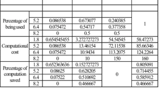
5.2 0.086538 0.673077 0.240385 6.4 0.075472 0.54717 0.377358 Percentage of being used 8.2 0 0.5 0.5 1 1.8 0.654545455 3.272727273 54.54545 58.47273 5.2 0.086538 13.46154 72.11538 85.66346 6.4 0.075472 10.9434 113.2075 124.2264 Computational cost 8.2 0 10 150 160 1.8 0.652363636 0.152727273 0.805091 5.2 0.08625 0.628205 0.714455 6.4 0.07522 0.510692 0.585912 Percentage of computation saved 8.2 0 0.466667 0 0.466667
Fig. 10. Performance of the adaptive recovery techniques for different packet loss rates (i.e., 1.8%, 5.2%, 6.4%, and 8.2%).
To evaluate the performance of the adaptive recovery mech-anism, we conduct empirical experiments to truly capture the network conditions and realize the corresponding impact to the recovery methods we considered. We implemented these recov-ery methods and incorporated the adaptive recovrecov-ery techniques into the H.323 system [19]. Then, we employ RTP (Real-Time Transfer Protocol) to measure the information of the packet loss periods [20]. The packet loss period distributions under four packet loss rates employed are examined in our experiments. As shown in Figure 10, we compute the probabilities of being used, computational costs, and the percentage of computation saved (as opposed to using only the DSPWR method) for the repetition method, the PWR method, and the DSPWR method under different packet loss rates.
V. CONCLUSION
In this paper, we developed a recovery method, DSPWR, which is able to tolerate a much higher packet loss rate than other schemes evaluated. In essence, DSPWR is composed of several procedures, procedures PSA, PMP, FWAA and BWAA, devised to improve the quality of the reconstructed speech. We evaluated the quality of the reconstructed speech under different packet loss rates for various kinds of receiver-based recovery methods, and compared the computational complexity among these methods. Under the acceptable speech quality whose MOS (Mean Opinion Score) is above 3.5, we developed an adaptive mechanism that can select the recovery method with the minimal complexity in accordance with different packet loss rates. To conduct real experiments in the networks, we imple-mented these recovery methods and evaluated the performance of DSPWR devised and the adaptive recovery techniques em-pirically. As validated by our experimental results, the adaptive mechanism was able to strike a compromise between the com-putational overhead and the quality of the speech desired. Sen-sitivity analysis on various parameters was also conducted. In view of the increasing popularity of Internet applications, the results in this study are very timely and important for the de-velopment of many related multimedia products of low cost and good quality.
ACKNOWLEDGEMENT
The authors are supported in part by the Ministry of Edu-cation Project No. 89-E-FA06-2-4-7 and the National Science Council, Projects No. NSC 89-22 8-E-002-028 and NSC 89-22 9-E-002-028, Taiwan, Republic of China.
REFERENCES
[1] G. Carle and E. W. Biersack, “Survey of Error Recovery Techniques for IP-Based Audio-Visual Multicast Applications,” IEEE Network, vol. 11, no. 6, pp. 24–36, November-December 1997.
[2] C. Perkins, O. Hodson, and V. Hardman, “A Survey of Packet-Loss Re-covery Techniques for Streaming Audio,” IEEE Network, vol. 12, no. 5, pp. 40–48, Sept-Oct 1998.
[3] N. Erdol, C. Castelluccia, and A. Zilouchian, “Recovery of Missing Speech Packets Using the Short-Time Energy and Zero-Crossing Measure-ments,”IEEE Transactions on Speech and Audio Processing, vol. 1, no. 3, pp. 295–303, July 1993.
[4] You-Li Chen and Bor-Sen Chen, “Model-Based Multirate Representa-tion of Speech Signals and Its ApplicaRepresenta-tion to Recovery of Missing Speech Packets,”IEEE Transactions on Speech and Audio Processing, vol. 5, no. 3, pp. 220–231, May 1997.
[5] V. Hardman, M. A. Sasse, M. Handley, and A. Watson, “Reliable Audio for Use over the Internet,”In Proceedings of INET’95, 1995.
[6] M. Yuito and N. Matsuo, “A New Sample-Interpolation Method for Recovering Missing Speech Samples in Packet Voice Communications,”
IEEE ICASSP-89, vol. 1, pp. 381–384, 1989.
[7] M. Podolsky, C. Romer, and S. McCanne, “Simulation of FEC-Based Error Control for Packet Audio on the Internet,” IEEE INFOCOM ’98, vol. 2, pp. 505–515, 1998.
[8] J. C. Bolot and A. Vega-Garcia, “The Case for FEC-Based Error Control for Packet Audio in the Internet,”To appear in ACM Multimedia Systems. [9] L. A. DaSilva, D. W. Peter, and V. S. Frost, “A Class-Oriented Replace-ment Technique for Lost Speech Packets,” IEEE INFOCOM ’89, vol. 3, pp. 1098–1105, 1989.
[10] D. J. Goodman, G. B. Lockhart, and O. J. Wasem, “Waveform Substi-tution Techniques for Recoverying Missing Speech Segments in Packet Voice Communications,”IEEE Transations on Acoust, Speech and Signal Processing, vol. ASSP-34, no. 6, pp. 1440–1480, December 1986. [11] O. J. Wasem, D. J. Goodman, and C. A. Dvorak, “The Effect of
Wave-form Substitution On the Quality of PCM Packet Communications,”IEEE Transations on Acoust, Speech and Signal Processing, vol. 36, no. 3, pp. 342–348, March 1988.
[12] J. Tang, “Evaluation of Double Sided Periodic Substitution (DSPS) Method for Recovering Missing Speech in Packet Voice Communica-tions,”Tenth Annual International Phoenix Conference on Computers and Communications, pp. 454 –458, 1991.
[13] R. A. Valenzuela and C. N. Animalu, “A New Voice-Packet Reconstruc-tion Technique,”IEEE ICASSP-89, vol. 2, pp. 1334 –1336, 1989. [14] H. Sanneck, A. Stenger, K. ben Younes, and B. Girod, “A New
Tech-nique for Audio Packet Loss Concealment,” Global Telecommunications Conference, pp. 48–52, 1996.
[15] W. Verhelst and M. Roelands, “An Overlap-Add Technique Based on Waveform Similarity (WSOLA) for High Quality Time-Scale Modifica-tion of Speech,”IEEE Workshop on Signal Processing Systems, pp. 220– 229, 1998.
[16] J. C. Bolot and A. Vega-Garcia, “Control Mechanisms for Packet Audio in the Internet,”IEEE INFOCOM ’96, vol. 1, pp. 232–239, 1996. [17] “Guide to MicrosoftR Windows NTR 4.0 Profiles and Policies in
Confer-ence Paper,”MSDN Libary.
[18] F. Marvasti, M. Hasan, M. Echhart, and S. Talebi, “Efficient Algorithms for Burst Error Recovery Using FFT and Other Transform Kernels,”IEEE Transactions on Signal Processing, vol. 47, no. 4, pp. 1065–1075, April 1999.
[19] International Telecommunications Union., “Recommendation H.323: Vi-sual Telephone Systems and Equipment For Local Area Networks which Provide a Non-Guaranteed Quality of Service.,” May 1996.
[20] H. Schulzrinne, S. Casner, R. Frederick, and V. Jacobson, “RTP: A Trans-port Protocol for Real-Time Applications,” IETF Audio/Video Transport Working Group, January 1996.