522 IEEE Transactions on Consumer Electronics, Vol. 48, No. 3, AUGUST 2002
A FRAME-BASED MPEG CHARACTERISTICS EXTRACTION TOOL
AND ITS APPLICATION IN
VIDEO
TRANSCODINGKan-Li Huang, Yi-Shin Tung, Ja-Ling Wu,
Senior
Member, /€E€, Po-Kang Hsiao and Hsien-Shuo Chen Communication and Multimedia LaboratoryDepartment of Computer Science and Information Engineering National Taiwan University, Taipei, Taiwan
Email: {shino, tung, wjl,. pkhsiao, macross}@cmlab.csie.ntu.edu.tw
Abstract
In this paper, we present a frame-based characteristics extraction tool, which can retrieve meaningful information from MPEG-compressed bitstreams. Taking advantage of the extracted information, we present
a
general architecture f o r MPEG video transcoding, which can transcode a given MPEG video bitstream into various MPEG video bitstreams with different characteristics. We also implement an MPEG-2-to-MPEG-4 video transcoder, which not only can change the bitstreams’ syntax and bitrate but also canencode each semantic video segment as a group of pictures
(GOPs), by using the techniques of flame type conversion
and video shot boundary detection. Moreover, the proposed transcoder can intelligently select motion mode for each macroblock of B-Vops in an MPEG-4 video to avoid some unpredictable artifacts due to mis-selection of motion mode. This representative application demonstrates the potential usage of such frame-based characteristics.
1.
Introduction
Video compression techniques are getting mature after years of efforts on the development of successful standards and de-facto codecs. The well-known moving picture expert group (MPEG) has published three versions of video codecs (MPEG-1
113,
MPEG-2 [ 2 ] , and MPEG-4 131). They are widespreadly used in digital video storage, presentation and transmission areas. By exploring these codecs in depth, we find that they not only can reduce the data rate explicitly but also can hide some meaningful information implicitly. The information hidden in the MPEG syntax is rich and worth to be investigated further to enhance the compression performance.In this paper, we present a frame-based characteristics extraction tool, which can retrieve meaningful information from MPEG-compressed bitstreams. The extracted characteristics are categorized into three classes: Temporal Similarity, Spatial Complexity and Region Perceptibility. By utilizing these Characteristics, we present a general architecture for MPEG video transcoding, which can transcode an MPEG video bitstream into various MPEG video bitstreams with different characteristics. Based on this architecture, we implement an MPEG-2-to-MPEG-4 video transcoder, which not only can change the syntax and bitrate of a bitstream, but also can encode each video segment into a group of pictures (GOPs) by using the techniques of frame type conversion and video shot boundary detection.
This paper is organized as follows. In section 2, we review techniques related to video transcoding. Section 3
demonstrates the proposed characteristics extraction tool. In section 4, we show how to apply the characteristics extraction tool to MPEG video transcoding. Section 5 provides the simulation results of the implemented transcoder. Finally, section 6 concludes our work.
2.
A Review
of Video Transcoding
Video transcoding is a method for converting a video from one format to another with different properties (such as frame size, frame rate, bit-rate and syntax). It is used for multiple purposes such as transmitting video over heterogeneous networks, displaying video on different devices, storing video into low-capacity storages, or providing universal video accesses. Video transcoder is a device to perform transcoding on videos. The simplest way to develop a video transcoder is directly cascading a source video decoder with a destination video encoder. Without using common information, this direct approach needs to fully decode input video and re-encode the decoded video by an encoder with different characteristics. Obviously, this direct approach is usually computationally intensive.
Generally, transcoding technology can be separated into two groups: homogeneous and heterogeneous transcodings. In homogeneous transcoding, source and destination videos are of the same compression format, such as MPEG-2-to-MPEG-2 transcoding. But heterogeneous transcoding transforms video from one compression format into another, such as MPEG-2-to-MPEG-4 transcoding. For homogeneous transcoding, many characteristics between source and destination videos are the same, such as picture coding types, coding techniques and parameter definitions. Through information re-using, decoder and encoder contained in a transcoder can be simplified to reduce the corresponding complexity. The main functionalities of a transcoder include bit-rate conversion [4,5], spatial resolution resizing [6,7] and frame rate reduction [6,8], which are activated adapting to variations of channel bandwidth, terminal capability and quality of service. In heterogeneous video transcoding [6,9,10], many characteristics between source and destination videos are different, such as coding methods, motion mode definitions and picture coding types. Therefore, information contained in source video cannot be directly used. After analyzing and modifying the extracted information, transcoder can still explore them to make transcoding process more efficiently.
Huang et-a].: A Frame-Based MPEG Characteristics Extraction Tool and Its Application in Video Transcoding 523
This technique is mainly applied to video editing and streaming applications. For example, MPEG videos can be transcoded into Motion P E G ones, which are more suitable for video editing than that of the MPEG counterparts. And an MPEG-2 video can be transcoded into MPEG-4 [9,10] for enhancing video streaming and video on demand applications.
3.
The Proposed Characteristics Extraction Tool
3.1 The Proposed Characteristics Extraction Tool
The frame-based characteristics of MPEG video can be classified into three groups: Region Perceptibility, Spatial Complexity, and Temporal Similarity, which will be described in the follows:
Region Perceptibility: This characteristic represents
the degree of visual importance for each region within a picture. In MPEG compressed bitstream, the. quantization scale (QS) of each macroblock can be used to represent this characteristic. Because the QS map has been embedded in the MPEG-compressed bitstream, the extraction tool can directly parse the video sequence to obtain it. Fig. l(a) shows the original picture and Fig. l(b) illustrates its corresponding QS map. The range of
QS values is from 1 to 31, and different QS values are represented by different degrees of brightness in the map. The darker colors, in Fig. l(b), stand for the larger
QS values. The darker regions are usually the regions
with complex textures and the bright regions are usually smooth areas. This reveals that the regions with complex textures can be coarsely quantized without introducing perceivable distortion according to the characteristics of human visual system ( H V S ) , but the smooth regions can just be slightly quantized so as to preserve visual quality. This explains why the QS map is suitable for describing the perceptibility of the corresponding picture.
Spatial Complexity: This characteristic indicates
which region is complex and needs more bits to encode it. The percentage of zero-quantized DCT coefficients for each macroblock, knows as p value [ll], can be used to represent this characteristic. Although 'this characteristic has not been utilized by h@EG it can be easily extracted from MPEG-compressed bitstreams, and therefore, has been applied to video source modeling and rate control [ l l ] , recently. Fig. l(c) shows the p map corresponding to the picture shown in Fig. l(a). The range of p values is from 0 to 1, which is also depicted by brightness. The darker colors stand for the larger p values. The regions with smaller p values usually need more bits to encode. From this figure, the regions with smaller p values usually possess complex structures and the areas with larger p values usually have more uniform structures. Therefore, this map is suitable for illustrating the complexity of the corresponding picture.
(3). Temporal Similarity': This characteristic describes the
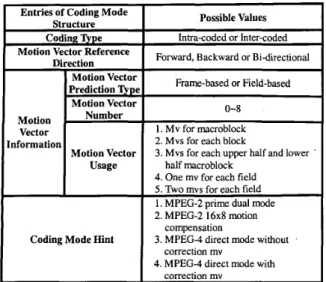
temporal relationships of a video sequence. In MPEG video, both motion vectors and coding modes can be applied to depict this information. In this work, we use coding mode structures as the indicators to describe this characteristic. The adopted coding mode structures are shown in Table 1 and described as follows:
A. Coding Q p e
This information denotes whether the current macroblock is intra-coded or inter-coded. It depicts the degree of the compensability of the current picture in the temporal domain.
B. Motion Vector Reference Direction
This information denotes the direction of motion reference, which can be forward, backward or bi-directionally. In other words, this information reveals the temporal referencing relationship of the current picture.
C. Information Relative to Motion Vector
We can depict the information, contained in the motion vector, from three parameters. The first is the motion vector prediction type, which denotes whether the motion vector is frame-based or field-based. The second is the motion vector number, which shows how many motion vectors are needed to perform motion compensation for each macroblock. The third is the motion vector usage, which depicts how motion vectors assist the motion compensation (MC) to form the final prediction. For example, motion vectors are used for each block in the four-motion mode, defined in MPEG-4, and motion vectors are used for upper half and lower half macroblocks in the 16x8 mode, defined in MPEG-2. Based on the above three parameters, the characteristics, contained in the motion vector, can be described in a more general way.
(a) Origin picture
(b) Quantization scale map (c) P map Figure 1 : The quantization scale map and p map of the flower
524 IEEE Transactions on Consumer Electronics, Vol. 48, No. 3, AUGUST 2002
Entries of Coding Mode Structure Coding ripe
Motion Vector Reference Direction Motion Vector Prediction Motion Vector Vector nformation Motion Vector Usage
I
Coding Mode Hint
Possible Values
Intra-coded or Inter-coded Forward, Backward or Bidirectional
Frame-based or Field-based
0-8
~
1 . Mv for macroblock 2. Mvs for each block
3. Mvs for each upper half and lower half macroblock
4. One mv for each field
5 . Two mvs for each field 1. MPEG-2 prime. dual mode 2. MPEG-2 16x8 motion
3. MPEG-4 direct mode without 4. MPEG-4 direct mode with
compensation correction mv correction mv
'
Table 1: Various coding mode structures
MPEG-Compressed Characteristics
Video Bitstreams Description
...
,.. ... 2
Figure 2: The architecture of the proposed characteristics extraction tool for MPEG-compressed video bitstreams
Videolnf o + :{l.Z ... N ,...) ... : RIsy 01' may not rsist
1 +
Figure 3: The hierarchy structure of the proposed intermediate representation o ~ t t p t n m c \%h Bitrtrcrrn ... "...I ... Daronqirrrsed \Ideo
Figure 4: The proposed architecture for MPEG video transcoder.
D. Coding Mode Hint
The coding modes, used by MPEG, usually contain some physical meanings. For example, direct mode, used in MPEG-4, reveals that the translation motion model is used in the current video segment. The coding mode hint keeps this information for further usage.
All information, mentioned above, can be directly extracted without fully decoding MPEG-compressed bitstreams. The architecture of our proposed extraction tool is shown in Fig. 2, which consists of three main components: the intermediate representer of our proposed frame-based characteristics, the characteristics extraction tool and the
MPEG video decoder. The MPEG video decoder just needs
to parse and perform variable length decoding on the input video sequence.
3.2 The Intermediate Format
Besides the frame-based characteristics as mentioned in the previous section, some other frame-level, scene-level or video-level features must also be explored to describe the whole video sequence, completely. We organize these characteristics into a hierarchy and treat the organized-hierarchy as a general intermediate format, as shown in Fig. 3, for providing cooperativeness and interchangeability. We summarize the features provided by the intermediate format as follows.
(1). VideoInfo: It describes the video-level properties, such
as the number of scenes cuts included in the current video, video frame rate, bit-rate and frame size, etc.
(2). SceneInfo: This feature represents the scene-level
information. Currently, it includes scene index number, 'the beginning frame index and the total number of frames in the scene.
(3). FrameInfo: It depicts the frame-level information such
as frame structure, field display priority, and display order. Many other characteristics are contained in the FrameInfo, such as Frame Buffer, Spatial Complexity, Region Perceptibility and Temporal Similarity. All these features are used to describe the frame-level characteristics, as prescribed in the previous section, of the current frame. In which FrameBuffer describes the information related to the frame buffer.
The proposed characteristics extraction tool for h4PEG-compressed video bitstreams and the intermediate representation of the extracted characteristics can be applied to many applications. In the next section, we will demonstrate the proposed application: the MPEG video transcoder.
4.
The Proposed MPEG Video Transcoder
Based on the proposed extraction tool and the prescribed intermediate representation, we propose an
Huang et al.: A Frame-Based MPEG Characteristics Extraction Tool and Its Application in Video Transcoding 525
architecture for conducting MPEG video transcoding, as shown in Fig. 4. The MPEG decoder first decodes the input W E G bitstream. The decoded information is fed into the proposed extraction tool for further processing or directly sent to the intermediate representer. After appropriately refining the intermediate representation, all necessary characteristics are exported to video encoder for assisting the encoding process. Under the proposed architecture, we can choose various video decoders, encoders and adaptation tools to transcode an MPEG video bitstream into another MPEG video bitstream with different characteristics. For example, using MPEG-2 video decoder, MPEG-4 video encoder and some rules for characteristics adaptation, we can construct an MPEG-2-to-MPEG-4 video transcoder. The proposed MPEG video transcoder architecture can easily extend to include other MC-DCT based video coding standards such as H.261 and H.263. In the following section, we will take the MPEG-2-toMPEG-4 video transcoder as an example to explain how to construct a typical video transcoder and discuss some issues about its implementation. We use transcoder in the following to stand for the MPEG-2-to-MPEG-4 video transcoder.
Before investigating the overall system, we describe the transcoding capabilities of the proposed MPEG-2-to-MPEG-4 video transcoder, first. The MPEG-2 video bitstream here refers to the non-scalable video bitstream defined in [2], and the MPEG-4 video bitstream refers to the bitstream, compliant to the simple profile, defined in [3], with the B-VOP coding. The proposed transcoder can perform the bit-rate conversion, the syntax conversion and the random accessing of the video shots. Although the proposed transcoder is restrained to specific functions, we can easily extend it to include other functionalities, such as frame rate conversion and spatial size conversion.
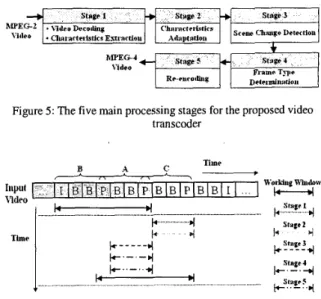
The proposed transcoding consists of five main process stages: the video decoding process, the characteristics adaptation process, the scene change detection process, the coding type determination process and the video re-encoding process. Fig. 5 shows these processing stages and the corresponding timing map of these five processing stages is shown in Fig. 6. In order to perform scene change detection and coding type determination processes, and to avoid the overhead of decoding the whole video sequence, we use sliding window technique to keep the necessary frames and execute the transcoding process one sub-GOP at a time. The working window usually keeps three sub-GOPs long. A sub-GOP includes many B frames surrounding with two reference frames that are I or P frames. Stages 3 and 4 of the transcoding process are used to equip the transcoder with the random access capability for browsing the video shots. If the computation power or memory capacity is insufficient, the transcoder can just skip these two processing stages and disable the working window to make transcoding process execute normally.
Figure 5: The five main processing stages for the proposed video transcoder
-
TimeThnor
I
Figure 6 : The timing map of the five main process stages The functionality of each processing stage is explained as follows:
(1). The Video Decoding Process Stage: This is the first
stage of the overall transcoding process. In this stage, the MPEG-2 video decoder decodes the input video bitstream, and sends the decoded bitstream to the proposed characteristics extraction tool. The extraction tool processes these decoded bitstreams, and extracts useful characteristics from them. And then, the extracted characteristics are kept in the intermediate representer, and sent to the next stage for further processing.
(2). The Characteristics Adaptation Process Stage: This
stage mainly performs two tasks. The first is to adapt the MPEG-2 characteristics to the MPEG-4 characteristics. The second is to perform some parameter conversion tasks, such as frame size conversion, frame dropping for frame rate conversion, etc. Many characteristics of the MPEG-2 bitstream must be modified to fit those defined in the MPEG-4. Some parameter conversion processes related to the transcoding process are summarized in the following:
A. The picture type conversion: MPEG-2 supports
progressive frames, interlaced frames and field pictures, but fame types used in the MPEG-4 are progressive frames and interlaced frames. Thus, two field pictures displayed at the same time need to be combined to form a progressive frame or interlaced frame, in the transcoding process. Many algorithms can be applied to this task to get better visual quality. For simplicity, we just combine two field pictures to construct the frame without any processing. In our experiments, most MPEG-2 video bitstreams use the progressive frame and the interlaced frame. Thus, this kind of
IEEE Transactions on Consumer Electronics, Vol. 48, No. 3, AUGUST 2002
The chrominance format conversion: The MPEG-4
format. Therefore, the chrominance format of the MPEG-2 bitstream must be converted to 4:2:0 format. simple profile only supports the 4:2:0 chrominance
526
B.
C.
A A i a * Y . O < a < I 4 > a.v,. I 5 < a il
no ~ c e t i e cliNi%e scene chniipc
&.. ’ ; ... :!...__
A;j
*..b;
Irllll
/1IklT
... , I . ... t . ...._.._tt
T,
, I ... MPEG-1 ( 3 ) MPEG-1 ( 3 ) 0 MPEG-2 (16) 13 MPEG-4 ( 9 ) 6other advanced algorithms can be applied to this
conversion for improving the visual quality and coding Figure 8: The window scheme for the scene change detection
MPEG-2 ( 16 ) MPEG-4 ( 9 ) 0 0 0 10 3 . 0 efficiency. tn . ~ r - u t t~~~~~
.
<D:%*nuClinnlr The motion information adaptation: The MPEG-2supports wider motion vector ranges than those supported by the MPEG-4. If the MPEG-2 bitstream uses larger motion range, the motion vector range must
be transferred to a suitable range and the motion
-
Case C’ase I Cast 2 Case 3vectors must also be refined, accordingly.
(a) Scene change at the I frame (b) Scene change at the P frame The motion modes, used in MPEG-1/2 and MPEG-4, CD SrP,,eC,Lwge T h e
.
are very different. Table 2 shows the motion modes CD CI) CD
need to be converted while transcoding among these three MPEG standards. The number in each parenthesis stands for the total motion modes used in each h4PEG transcoding, ten motion modes need to be modified rule-based scheme to handle this conversion, as shown in Fig. 7. These transcoding rules are mainly used for choosing the appropriate candidate motion vectors for
each macroblock in the current frame. These rules may Case 4 Case 5 Case 6 be derived based on a complicated algorithm or just
come form some simple heuristics. For simplicity, in our implementation, simple heuristic rules are used to select the candidate motion vectors.
coding standard. In the MPEG-2-to-h4PEG-4 video Case
-
while the others can be directly used. We adopt the CD .4 K CI) L hi
(c) Scene change at the B frame Figure 9: The frame type changing rules
Video TI ;u~rc&ig Ruk
B ai& No Rule D e s r ~ p t l e r i Rl Riilc Selector Fmrwntd mode t o f o i x m r d mode ’ Iufoimatiou
Figure 7: The rule-based transcoding scheme
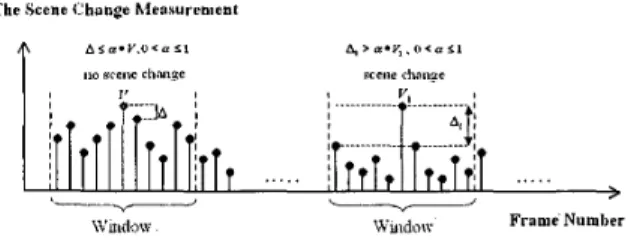
(3). The Scene Change Detection Process Stage: The
scene change detection process is to detect the video shot boundary. The proposed transcoder implements the pixel domain comparison approach [ 121 for achieving shot detection and uses the window scheme to filter out some false alarm frames. For any frame, if the scene change measurements of the neighbor frames are not relatively small (i.e. still larger than a threshold), the transcoder will not take the current frame as a scene change frame. Fig. 8 shows the corresponding process.
(4). Frame Type Determination Process Stage: At this
stage, the new coding type of each frame is decided not only to facilitate the cut-and-paste functionality of an arbitrary scene in the output bitstream, but also to encode the video efficiently. If scene change doesn’t occur, we will reuse coding patterns of the original video bitstream, but if scene change is detected on some frames, the frame coding types of those frames have to be changed to “I” type, and those of their immediate previous frames have to be changed to “I” type or
“P”
type, dependingon
the coding patternof
the original frame. Under the assumption that an object motionHuang et al.: A Frame-Based MPEG Characteristics Extraction Tool and Its Application in Video Transcoding 527 in several successive frames of the same scene can be well
approximated by a linear motion model, the special coding mode (direct mode) of the MPEG-4 can operate well, in this way.
Based on the above discussions, the rules for changing the frame coding types can be separated into three cases, which are shown in Fig. 9 and are summarized as follows:
A. The scene change occurs at the I frame: The
transcoder does not change the frame coding type of the scene change frame. We take the case 3, shown in Fig. 9 (a), as an example. Let frame K stands for the frame immediately before the scene change frame and frame group A means the frames, whose frame coding type is B, immediately before the frame K. Then the frame coding type of the frame K is converted to P type and the backward motion information of the frame K is discarded. And the backward motion vectors of the frame group A are scaled, according to the distance to the new reference frame, for further refinement.
B. The scene change occurs at the frame whose coding
type is P type: The transcoder changes the frame coding
type of the scene change frame to I type and discards all the motion information. In cases 1 and 2 of Fig. 9 (b), because the frame immediately before the scene change frame is I- or P-type, the transcoder keeps the original coding type. In case 3 of Fig. 9 (b), the frame coding type
of the frame K is converted to P type. The backward motion information of the frame K is discarded. And the backward motion vectors of the frame group A are scaled, according to the distance to the new reference frame, for further refinement.
C. The scene change occurs at the frame whose coding
type is B type: The transcoder changes the frame coding
type of the scene change frame to I type and discards all the motion information. Because the coding type determination rules are very similar in the cases 1, 2, 4 and 5 of Fig. 9 (c), we only explain the rules for the case 4 and the same reason is also applied for cases 5 and 6, of Fig. 9 (c). Thus, we only explain the rules for the case 4 and the case 6 . The other cases can be derived accordingly.
In the case 4, the frame K stands for the future reference frame of the scene change frame and the frame group A means the frames, whose frame coding type is B, immediately after the scene change frame. The transcoder performs two operations for conducting this the process stage:
(i). The coding type of the scene change frame is set to I
type and all the motion information are discarded.
In the case 6, the frame K stands for the frame immediately before the scene change frame and the frame group A means the frames, whose frame coding type is B, immediately before the frame K. The frame M stands for the future reference frame of the scene change frame and the frame group L means the frames, whose frame coding type is B, immediately after the scene change frame. The transcoder performs three operations for conducting the process stage:
(i). The coding type of the scene change frame is set to I
type and all the motion information are discarded.
(ii). The coding type of the frame K is converted to P type
and the backward motion information of the frame K are also discarded.
(iii). The forward motion vectors of the frame group L
and the frame M are scaled, according to the distance to the new reference frame, for further refinement.
(5). The Video Re-encoding Process Stage: This final
stage re-encodes the video sequence into the MPEG-4 compliant bitstreams. In order to speed-up the encoding process and improve the video quality, the transcoder re-uses and refines the extracted characteristics to achieve these goals. In our proposed transcoder, we perform the following additional functions during the video encoding process.
A. Refining, reusing and re-estimating motion vectors.
Because the transcoder performs the coding pattem determination process and explores the MPEG-4 advance motion modes, the motion vectors contained in the intermediate representer may need to be refined or just reused, and sometimes, new motion vectors also need to be re-estimated.
B. The coding mode determination for each macroblock.
In order to explore the coding efficiency of the MPEG-4, the transcoder doesn't reuse the coding mode of each macroblock of the original bitstream. The MPEG-4 encoder determines the new coding mode for each macroblock.
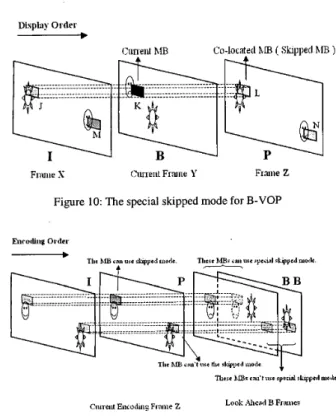
C. Intelligent motion mode selection for B-Vop.
In MPEG-4, if the co-located macroblock in recently decoded reference VOP is coded with no DCT coefficients, the current macroblock in B-VOP must be encoded with zero motion vector and no DCT coefficients. This motion mode assumes that the two referencing frames have very slight motion activity and the frames between them also have little motion activity. Therefore, this motion mode works well for video sequences with normal motion behavior. But it causes some artifacts for video sequences with fast and abnormal motion behavior.
(ii). The forward motion vectors of the frame group A and
the frame K are scaled, according to the distance to the
IEEE Transactions on Consumer Electronics, Vol. 48, No. 3, AUGUST 2002 528
Display Ordrr
-
the succeeding B frames. If one of these rulei is matched,current macroblock in P frame cannot be allowed to code with the skipped mode. The adopted heuristic rules are summarized as follows:
(a). In P frame, the extracted coding mode of the current
macroblock is intra-coded.
(b). In P frame, the extracted coding mode of the current
macroblock is inter-coded with large motion Co-located \IB Shlll)ed ’IB
Fnuiir S ( l u ~ r n t Fmne Y Frme Z vectors.
Figure 10: The special skipped mode for B-VOP
Figure 11: The determination method for the special skipped mode for B-VOP
We take Fig. 10 as an example to explain this phenomenon. Because the macroblock L in the recently decoded VOP is in skipped mode, the current macroblock K
must be encoded with zero motion vector and no DCT coefficients by the MPEG-4. But the macroblock K should use the macroblock M or N to estimate the motion vectors and the prediction residues, and therefore, some unpredictable artifacts will appear. Two methods can solve this problem:
(i). This first method directly applies for the decoded video
data. Before encoding the I/P frame, the encoder looks ahead the succeeding B frames and checks the similarity between the macroblocks in the P frame and the co-located macroblocks in the succeeding B frames. If the current macroblock in
I/€’
frame is similar to all the co-located macroblocks in the succeeding B frames, the current macroblock can be coded in the skipped mode, which also enables the special skipped mode for all co-located macroblocks in the succeeding B frames. Due to the queuing of the succeeding B frames and the similarity calculation, the coding delay and the buffer size are increased. Fig. 11 illustrates this approach.(ii). The second method uses three heyistic rules, based on
the extracted motion information, to determine if the current macroblock in the P frame can be coded in the skipped mode or not, which also enables the usage of the special skipped mode for the co-located macroblocks in
(c). In P frame, the extracted coding mode of the current
macroblock is inter-coded with small motion vectors, but there exists inter-coded, which are of the co-located macroblocks in the succeeding B frames, with large motion vectors.
Because this method only needs motion information, the buffer size can be significantly reduced and the time spends for executing the special skip mode determination process can also be reduced.
5.
Simulation Results
This section provides the simulation results of the proposed MPEG-2-to-MPEG-4 video transcoder. Table 3 shows the parameters for each test video sequence. And Table 4 shows the test environment. The peak signal-to-noise ratio (PSNR) is taken to measure the video quality. Based on each mean-square error (MSE), the PSNR for each color component (Y, Cb, Cr) is separately calculated. The equation for PSNR calculation is as follows:
PSNR = lO*log,,( 255‘ ) dB, Index E [ Y , Cb, Cr ] (1)
MSE ( Index
The performance measurement is based on the following equation:
Excution Time( Y )
Excution Time( X ) Speed - up =
Simulation I: We transcode the test sequences 1 and 2,
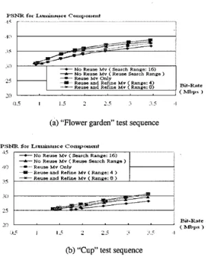
with bit-rate 0.9 megabits per second (Mbps), 1.2 Mbps, 1.5 Mbps, 1.8 Mbps, 2 Mbps, 2.5 Mbps, 3 Mbps and 3.5 Mbps, respectively. The representative frames, transcoded with only reusing motion vectors from test video sequences 1 and 2 (all with bit-ratel.5 Mbps), are shown in Fig. 12. It is observed that these transcoded video sequences, at 1.5 Mbps, have acceptable visual quality. Fig. 13 shows the PSNR vs. Bit-rate relationships for the test sequences 1 and 2, respectively. We examined five different motion estimation methods for each test sequence, as described follows:
(1). No Reuse Mv (Search Range 16): This method
encodes the decoded . MPEG-2 video sequences and performs motion estimations with 16-pixel motion search range.
Huang et al.: A Frame-Based MPEG Characteristics Extraction Tool and Its Application in Video Transcoding 529
cpu
Memory Hard OperatingDisk System Pentium-aI 128 MB ATA-66 Windows 2000
(2). No Reuse Mv (Reuse Search Range): This method
encodes the decoded MPEG-2 video sequences and performs motion estimations by reusing the motion search ranges extracted from the input bitstreams.
(3). Reuse Mv Only: This method encodes the decoded
MPEG-2 video sequences and reuses the motion vectors extracted from the input bitstreams.
Programming Profde Environment Tool
NuMega Visual C++ 6.0 TrueTime
2.1
(a) Frame 20 of the “Flower Garden” sequence at 1.5 hfbps
(4). Reuse and Refine Mv (Range: 4): This method
encodes the decoded MPEG-2 video sequences and takes the extracted motion vectors as predictors for further refinements with a fixed 4-pixel search range.
(5). Reuse and Refine Mv (Range: 8): This method encodes the decoded MPEG-2 video sequences and takes the extracted motion vectors as predictors for further refinements with a fixed 8-pixel search range.
In these experiments, two phenomena are observed. The first is that the proposed transcoder cannot compress the test video sequences with the bit-rates less than 0.9 Mbps. Especially, the “Flower Garden” sequence cannot be compressed with the bitrate lower than 1.3 Mbps. This is because the proposed transcoder did not implement the frame dropping and macroblock skipping mechanisms. Thus, without these violent rate control schemes, the bit-rates of the test bitstreams cannot be largely reduced. The second phenomenon is that the methods 3 and 5 gain better PSNRs than method 2. The motion estimation algorithm, used by methods 1 and 2, finds the motion vectors with the lowest mean square error (MSE) but does not take the bit-rate consumed by estimated motion vectors into account. And this approach may not be the optimal motion estimation method for the video sequences with constant bit-rate constraint.
Table 3: Parameters for test video sequence (Test Video 1,2 come from
htt~://hmr~.herkcle~.edu/ft~/oub/multimedia/m~e~//m~eg2/co nfoiinance-bitstrcams/Tektronix/)
I
HardwareI
SoftwareI
Table 4: The simulation environment
(b) Frame 54 of the “Cup” sequence at 1.5 Mbps Figure 12: The pictures on the left side are original
images, and the right ones are the transcoded pictures.
1 0 I
(MPEG-2) (MPEG-4)
(a) “Flower garden” test sequence PSNR f o r Liuuuiiuire C‘o~iipoiit.lit
-+- NO Reuse M v ( Reuse Search Range ) Reuse M V Only
Reuse and Refme Mv (Range: 4 > * Reuse and Refme Mv (Range: 8 )
I
e)
“Cup” test sequenceFigure 13: The PSNR vs. bit-rate relationships of different video sequences.
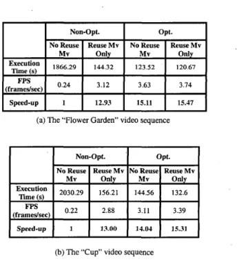
Simulation 11: This simulation demonstrates how the
extracted motion vector speeds up the transcoding process. The proposed transcoder consists of two components. One is the MPEG-2 decoder, developed by the MPEG simulation group. The other is the MPEG-4 encoder, developed by the Communication and Multimedia Laboratory at the department of the Computer Science and Information Engineering, National Taiwan University. In this simulation, we take “Flower Garden” and “Cup” as test sequences. We
530 IEEE Transactions on Consumer Electronics, Vol. 48, No. 3, AUGUST 2002 Execution Time (s) Fps (framedsec) Speed-up
also compare the speed-up of optimized and non-optimized transcoders. The optimized transcoder uses many optimization techniques for enhancing the encoding process and the decoding process, such as fast motion estimation algorithms, Intel’s MMWSSE techniques and fast DCT algorithms. The non-optimized transcoder is implemented by pure C code and uses the DCT algorithm adopted in the MPEG-2 and MF’EG-4 reference softwares. The comparison results of the speed-up are shown in Table 5. The baseline for performance comparison is founded on the performance of the non-optimized transcoder. This simulation reveals the following phenomena.
Non-Opt. opt.
No Reuse Reuse Mv No Reuse Reuse Mv
Mv Only Mv only
144.32 123.52 120.67 1866,29
0.24 3.12 3.63 3.74
1 12.93 15.11 15.47
Due to elimination of the motion estimation process, reusing motion vectors can significantly improves the performance of the non-optimized transcoder, but the optimized transcoder gains only a little improvement. This is because the execution time for the motion estimation process has been optimized to occupy only a small portion of the overall transcoding time; meanwhile, other modules of the transcoding process have not been optimized at all.
Simulation 111: In this simulation, the intelligent
motion mode selection method (IMMSM), which has been described in the section 4.(5)-C, is used to conduct the motion estimation for B-Vop. Fig. 14 (a) to (d) show the snapshots of the “Dragon” video sequence, which are encoded without using the IMMSM. Fig. 14 (e) to (h) show the snapshots of the “Dragon” video sequence, which are encoded by using the IMMSM. From Fig. 14, we found that IMMSM can significantly reduce the artifacts, resulting from an inappropriate coding mode selection.
Table 6 shows the execution time of the transcoding process, the execution time of the IMMSM module and the total number of skipped modes in the B-Vops. The numbers in parentheses denote the counts corresponding to the IMMSM approach. The execution time of the IMMSM module using method I is longer than that of the method 11, but the total execution time, using method I, is shorter than that of using method 11. The puzzle comes from the fact that method I1 using heuristic rules but method I using the pixel-wise comparison for skipped mode selection. Therefore, the execution time of the IMMSM module using method I is longer than that of using method 11. If the number of the skipped modes in the B-Vop increases, the transcoder will spend more time for coding mode determination process, which may reduce the performance gained from method II. Table 6 has revealed this phenomenon.
6.
Conclusions
In this paper, we present a frame-based characteristics extraction tool for MPEG-compressed video bitstreams and apply it to MPEG video transcoding and descriptor generation. We also use- an intermediate representation to describe the extracted characteristics. Due to its flexibility, the proposed intermediate representation can be a bridge for
information changing among many applications, such as video compression, transcoding, description generation and analysis, etc. Based on that architecture, we implement an MPEG-2-to-MPEG-4 video transcoder, which adopts the spatial domain approach to transcode the MPEG-2 video bitstream into the MPEG-4 video bitstream. The transcoder can also perform the bit-rate conversion, the syntax’ conversion and the random accessing of the video shots. During the transcoding process, we use the motion information, included in the intermediate representation, for intelligently selecting motion modes. We also propose the general architecture for MPEG video description generation. In conclusion, the proposed effective characteristics extraction tool for the MPEG-compressed video bitstreams and the intermediate representation can benefit many applications especially for content-based retrieval and video transcoding. It is our believed that the proposed tool and the intermediate representation will play an important role in the multimedia world.
Acknowledgement
The authors would thank Chia-Chiang Ho, Jin-Hau Kuo, Chun-Hsiang Huang and Yuh-Jue Chuang for their assistance on this work. This project is partially sponsored by the National Science Council (NSC, Taiwan) under the grant number NSC90-2622-E-002-008.
I
I
Non-Opt.I
opt.I
I I No Reuse I Reuse Mv IN0 Reusel Reuse Mv I Execution
Time ( s )
(framedsec)
(b) The “Cup” video sequence
Table 5 : The simulation results for the transcoders with motion vectors reuse.
Huang et al.: A‘Frame-Based MPEG Characteristics Extraction Tool and Its Application in Video Transcoding 53 1
Dragon (I) Dragon (II)
(a) Frame 696 (b) Frame 697 (c) Frame 698 (d) Frame 699
lkanscoding Execution Time Skipped Mode Execution Time (s)
IMgM
(s) No In B-Vops67.28 (100%) 0.32 (0.48 %) 930 67.24 (100%) 0.08 (0.12 %) 1428 (e) Frame 696 (0 Frame 697 (g) Frame 698 (h) Frame 699 Figure 14: The snapshots of the “Dragon” video sequence. The
upside pictures are encoded without using the intelligent motion mode selection method, and the downside ones are encoded with using the intelligent motion mode selection method. (Frame Coding Type: IBBP)
I
G:E:iI)I
137.24(100%)I
0.39(0.28%)I
25488I
Flower Garden (II)
Cup(1)
I
141.48 (100%)‘ 1
0.41 (0.29%)I
16157 c u p (11)I
143.71 (100%)I
0.04 (0.03 %)I
5998Table 6: The simulation-results of the intelligent motion mode selection method.
Reference
International Organization for Standardization (ISO), “ISOAEC 11 172-2, Information Technology - Coding of moving pictures and associated audio for digital storage media at up to about 1.5MbiVs: Part 2
-
Video.” May 1993. International Organization for Standardization (ISO), “ISOAEC 138 18-2, Information Technology-
Generic coding of moving pictures and associated audio information:Part 2
-
Video”, 1995.International Organization for Standardization (ISO), “ISOAEC IS 14496-2, Information Technology
-
Coding of Audio-visual Objects: Part 2-
Visual,’’ 1998.H. Sun, W. Kwok, and J. W. Zdepski, “Achitectures for MPEG compressed bitstream scaling,” IEEE Transactions on Circuits Systems and Video Technology, vol. 6, no. 2, pp. 191-199,Apr. 1996.
P. Assuncao and M. Ghanbari, “A frequency-domain video transcoder for dynamic bit-rate reduction of MPEG-2 Bit Streams,” IEEE Transactions on Circuits Systems and Video Technology, vol. 8, no. 8, pp. 953-967, Dec. 1998.
T. Shanableh and M. Ghanbari, “Heterogenous video
transcoding to lower spatial-temporal resolutions and different encoding formats,” IEEE Transaction on Multimedia, vol. 2, no. 2, pp.101-110, Jun. 2000.
G Shen, B. Zeng, Y.-Q. Zhang, and M. L. Liou, “Transcoder with arbitrarily resizing capability,” 2001 IEEE International Symposium on Circuits and Systems Sydney, Australia, May. K. -T. Fung, Y. -L Chan and W. 4. Siu, “ Low-complexity
and high quality frame-skipping transcoder,” 2001 IEEE Intemational Symposium on Circuits and Systems Sydney, Australia, May. 6-9, 2001.
W. X. Guo, Z W Cuo, and I. Ahmad, ”MPEG-2 to MPEG-4 transcoding,” MPEG-4. 2001 Proceedings of Workshop and Exhibition on, pp. 83-86,2001.
J.’ NAKAJIMA, H. TSUJI, Y. YASHIMA, and N. KOBAYASHI, “Motion vector re-estimation for fast video transcoding from MPEG-2 to MPEG-4,” MPEG-4. 2001 Proceedings of Workshop and Exhibition on, pp. 87- 90, 2001.
Z. He, Y. K. Kim and Sanjit K. Mitra, “Low-delay rate control for video coding via p-domain source modeling,” IEEE Transactions on Circuits and Systems for Video Technology, Vol. 11, No. 8, pp. 928-940, Aug. 2001. R.Brunelli, 0. Mich, and C. M. Modena, “A Survey on the Automatic Indexing of Video Data,” in Journal of Visual Communication and Image Representation 10, pp. 78-1 12, 1999.
6-9,2001.
BIOGRAPHY
Kan-Li Huang received the B.S. degree in computer science and informption engineering from National Taiwan University, Taipei, Taiwan, in 1998. He is currently a master student in the Dept. of Computer Science and Information Engineering, National Taiwan University. His current research interests include image and video coding, multimedia systems, scalable codecs, video transcoding an; optimization techniques for video compression algorithms.
Yi-Shin Tung received the B.S. degree in computer science and information engineering from National Taiwan University, Taipei, Taiwan, in 1996. He is currently a Ph.D. student in the Dept. of Computer Science and Information Engineering, National Taiwan University. His current research interests include image and video coding, multimedia systems, scalable codecs, and stremng audio and video.
~
512 IEEE Transactions on Consumer Electronics, Vol. 48, No. 3, AUGUST 2002
Ja-Ling Wu received the B.S. degree in electronic engineering from TamKang University, Tamshoei, Taiwan, R.O.C. in 1979, and the M.S. and Ph.D degree in electrical engineering from Tatung lnstitue of Technology, Taipei. Taiwan, in 1981 and 1986, respectively.
From 1986 to 1987, he was an Associate professor of the Electrical Engineering Department at Tatung Institute of Technology, Taipei, Taiwan. Since 1987, he has been with the Department of Computer Science and Information Engineering, National Taiwan University, where he i s presently a Professor. He was also the Head of the Department of Information Engineering, National Chi Nan University, Puli, Taiwan, from Aug. 1996 to July. 1998.
Prof. Wu was the recipient of the 1989 Outstanding Youth Medal of the Republic of China, the Outstanding Research Award sponsored by the National Science Council. from 1987 to 1992, and the Excellent Research Award from NSC, 1999.
Prof. Wu has published more than 200 joumal and conference papers. His research interests include algorithm design for DSP, data compression, digital watermarking techniques and multimedia systems.
Po-Kang Hsiao was born in Hsinchu, Taiwan in 1976. He received the B.S. degree in computer science and information engineering from National Taiwan University, Taipei, Taiwan in 1998. From 1998 to 2000, he joined the army of R.0.C as a second lieutenant personnel/ adminisvation officer. He is currently a master student of the Communications and Multimedia Laboratory in National Taiwan University. His research interests are in the area of digital media compression, digital image and video processing, multimedia systems, and streaming media technology
Hsien-Shuo Chen received the B.S. degree in computer science from National Tsing Hua University,,Hsinchu, Taiwan, R.O.C. in 2001. He is currently
a M.S. student in the department of
computer science and information eneineerine, National Taiwan University.