二氧化碳渦卷式壓縮機渦片尺寸的分析與設計
80
0
0
全文
(2) 二氧化碳渦卷式壓縮機渦片尺寸的分析與設計 Dimensional Analysis and Design of Scroll Wrap of CO 2 Scroll Compressor 研究生:王秀惠. Student: Hsiu-Hui Wang. 指導教授:曾錦煥 教授. Advisor: Ching-Huan Tsen. 國立交通大學 機械工程研究所 碩士論文. A Thesis Submitted to Institute of Mechanical Engineering College of Engineering National Chiao Tung University in Partial Fulfillment of the Requirments for the Degree of Master of Science in Mechanical Engineering. June. 2004 Hsinchu, Taiwan, Republic of China. 中華民國九十三年六月.
(3) 二氧化碳渦卷式壓縮機渦片尺寸的分析與設計. 研究生:王秀惠. 指導教授:曾錦煥 教授. 國立交通大學機械工程研究所. 摘要. 在環保因素的考量之下,自然冷媒應用在壓縮機上將會是未來發展的趨勢。在本論 文中,採用不可燃且無毒性之二氧化碳自然冷媒,結合高效率、低噪音、低振動之渦卷 式壓縮機,來作一分析與設計。由於二氧化碳之低臨界溫度與高臨界壓力之特性,使得 壓縮機之工作壓力會較目前使用之冷媒的壓縮機高許多,因此利用工研院能資所自行開 發之『渦卷式壓縮機之性能模擬軟體』來模擬分析壓縮機之性能效率,再加上有限元素 分析針對渦卷葉片尺寸強度作分析設計,來作為新設計上之指標。依據分析的結果,由 於使用二氧化碳時,壓縮機之壓縮壓力差太大,而易造成渦卷之損壞,因此在論文之最 後並針對兩段式渦卷式壓縮機作一專利回顧,並提出一概念設計。. i.
(4) Dimensional Analysis and Design of Scroll Wrap of CO 2 Scroll Compressor. Student: Hsiu-Hui Wang. Advisor: Ching-Huan Tseng. Institute of Mechanical Engineering National Chiao Tung University. ABSTRACT. The nature refrigerants will be a trend in the future under the considerations of environmental protection. In this thesis, an non-flammable and non-toxic nature refrigerant, CO 2 , and a scroll compressor which has some advantages such like high efficiency, low. noise, and low vibration, are taken into analysis and design. The working pressure of scroll compressor using CO 2 is much higher than using present refrigerants for the low critical temperature and high critical pressure properties of CO 2 , so the performance of scroll compressor where the “Performance Simulation Program of Scroll Compressor” offered from the Industrial Technology Research Institute, and it also considers the finite element analysis is used to analyze the strength of scroll wrap to design the dimensions of scroll wrap. The pressure difference of compressor using CO 2 is so great to make scrolls damage easily, therefore, there are descriptions about patents of the two-stage compression type of scroll compressor, and proposes a concept design in the end of this thesis.. ii.
(5) ACKNOWLEDGEMENT I feel an immense gratitude to my advisor, Dr. Ching-Huan Tseng. He not only taught us about how to do the research but also told us the way of getting along with people that will be much helpful to us no matter what situations we meet over the whole life. And then, I am grateful to Yu-Choung Chang and Ching-feng Lai in Energy and Resources Laboratories of Industrial Technology Research Institute for providing me many resources and advices during the study time. Finally, I want to tell all guys in AODL that it is very joyful to get along with you, and thank all my friends for standing by me all the time.:). iii.
(6) TABLE OF CONTENTS. ABSTRACT (IN CHINESE)....................................................................................................i ABSTRACT..............................................................................................................................ii ACKNOWLEDGEMENT..................................................................................................... iii TABLE OF CONTENTS........................................................................................................iv LIST OF TABLES..................................................................................................................vii LIST OF FIGURES ............................................................................................................. viii PARAMETER LIST ................................................................................................................x CHAPTER 1 INTRODUCTION ............................................................................................1 1.1. Motivations ........................................................................................................1 1.2. Thesis Organization ..........................................................................................2 CHAPTER 2 CO 2 AS REFRIGERANT..............................................................................3 2.1. Refrigerants and Environment ........................................................................4 2.2. CO 2 Refrigerant..............................................................................................6 2.2.1. Advantages of CO 2 Refrigerant..................................................7 2.2.2. Issues of CO 2 Refrigerant ...........................................................7 CHAPTER 3 SCROLL COMPRESSOR...............................................................................9 3.1. Operation Principle ..........................................................................................9 3.2. Issues of CO 2 Scroll Compressor.................................................................10 3.3. Geometric of Scroll Wrap .............................................................................. 11 3.3.1. Extend Involute Curve ................................................................12 3.3.2. Profile of Scroll Wrap ..................................................................14 3.3.3. Scroll Wrap Pair ..........................................................................15 3.4. State of Compressed Gas ................................................................................17 iv.
(7) CHAPTER 4 SIMULATION PROGRAM ..........................................................................19 4.1. Performance Simulation Program of Scroll Compressor ...........................19 4.2. Modify the Simulation Program....................................................................19 4.3. Results and Discussions ..................................................................................24 CHAPTER 5 FINITE ELEMENT METHOD ....................................................................25 5.1. ANSYS Parametric Design Language...........................................................25 5.2. Scroll Compressor Structure..........................................................................26 5.3. Refrigeration Cycle.........................................................................................27 5.4. Scroll Model.....................................................................................................28 5.4.1. Material Properties ......................................................................29 5.4.2. Boundary Conditions...................................................................30 5.5. Analysis and Results .......................................................................................32 5.6. Discussions .......................................................................................................38 CHAPTER 6 OPTIMUM DESIGN .....................................................................................39 6.1. Design Problem ...............................................................................................39 6.1.1. Design Variables ...........................................................................39 6.1.2. Cost Function ...............................................................................41 6.1.3. Design Constraints .......................................................................42 6.1.4. Design Flow Chart .......................................................................43 6.2. Results and Discussions ..................................................................................45 CHAPTER 7 CONCEPT DESIGN OF SCROLL COMPRESSOR OF TWO-STAGE COMPRESSION TYPE ........................................................................................................48 7.1. Patents Review ................................................................................................48 7.2. Concept Design................................................................................................53 CHAPTER 8 CONCLUSIONS.............................................................................................55 REFERENCES.......................................................................................................................57 v.
(8) APPENDIXES I DATA OF FINITE ELEMENT ANALYSIS ...........................................60 APPENDIXES II DATA OF OPTIMUM DESIGN ............................................................62. vi.
(9) LIST OF TABLES. Table 2.1.1 Characteristics of some refrigerants (Lorentzen,1995; VDI, 1994).....................5 Table 2.2.1 The history of CO 2 as refrigerant........................................................................6 Table 4.2.1 Major specification of scroll compressor in [Ishii, 2002] ..................................20 Table 4.2.2 Dimensions of scroll wrap .................................................................................21 Table 4.2.3 The suction and discharge states of CO 2 ..........................................................22 Table 4.2.4 Input data of the simulation program .................................................................23 Table 5.3.1 Temperatures of refrigerant cycle ......................................................................27 Table 5.4.1 Dimensions of scroll wrap of the scroll compressor for R410A........................28 Table 5.4.2 Properties of cast iron ........................................................................................29 Table 5.5.1 Analysis results of orbiting scroll ......................................................................33 Table 6.1.1 Design data of design variables .........................................................................40. vii.
(10) LIST OF FIGURES. Fig. 2.2.1 Pressure-enthalpy diagram of CO 2 refrigeration cycle (1)....................................8 Fig. 3.2.1. Operation of scroll compressor.............................................................................10. Fig. 3.3.1. Generation of scroll wrap ..................................................................................... 11. Fig. 3.3.2. The coordinate system of an extended involute curve .........................................13. Fig. 3.3.3. Relationship between two scrolls (1)....................................................................16. Fig. 3.3.4. Relationship between two scrolls (2)....................................................................17. Fig. 4.2.1 Pressure-enthalpy diagram of CO 2 refrigeration cycle (2)..................................22 Fig. 5.2.1. Assembly relation of scroll compressor structure [賴,1998].............................26. Fig. 5.3.1 Pressure-enthalpy diagram of CO 2 refrigeration cycle (3)..................................27 Fig. 5.4.1. SOLID45 3-D structural solid ..............................................................................28. Fig. 5.4.2. Mesh model of orbiting scroll ..............................................................................29. Fig. 5.4.3. Compression chambers of scroll compressor .......................................................30. Fig. 5.4.4. Constraint conditions of orbiting scroll ................................................................31. Fig. 5.5.1. Stress distribution of orbiting scroll .....................................................................33. Fig. 5.5.2. EER and safety factor versus scroll wrap height..................................................35. Fig. 5.5.3. EER and safety factor versus discharge pressure .................................................36. Fig. 5.5.4. Pressure difference between chambers versus discharge pressure .......................37. Fig. 5.5.5. Pressure difference between chambers versus scroll wrap height........................37. Fig. 6.1.1 Optimum design flow chart .....................................................................................44 Fig. 6.2.1. Results of optimum design, scroll wrap thickness vs. safety factor .....................47. Fig. 6.2.2. Results of optimum design, scroll wrap thickness vs. EER .................................47. Fig. 7.1.1. Sectional view of scroll compressor of US6,050,792 ..........................................49. Fig. 7.1.2. Sectional view of scroll compressor of US5,304,047 ..........................................51 viii.
(11) Fig. 7.1.3. Cross-sectional view of the lower-stage compression part of the scroll. compressor of Fig. 7.1.2 ..........................................................................................................51 Fig. 7.1.4. Sectional view of scroll compressor of US5,624,247 ..........................................52. Fig. 7.2.1. Concept design of a two-stage compression scroll compressor ...........................53. ix.
(12) PARAMETER LIST. d T Diameter of the milling tool. D Cylinder diameter Gr Refrigerant flow rate. ′ Gr Refrigerant flow rate without volumetric loss h. Scroll height. hs. Refrigerant enthalpy value at compressor inlet. hT. Height of the milling tool. hv. Refrigerant enthalpy value at expansion valve export. k. Specific heat ratio. N. Number of circles of wrap. p. Scroll pitch. Pd. Discharge pressure. Ps. Suction pressure. Qc Cooling capacity rb. Involute base circle radius. ro. Orbiting radius. s. Refrigerant entropy value. t. Scroll thickness. Td. Discharge temperature. Te. Temperature at evaporator. Ts. Suction temperature. Tv. Temperature at expansion valve inlet x.
(13) Vs. Suction volume. δ a Axial clearance δr. Radial clearance. η v Volumetric efficiency θ d Discharge start angle ρ s Density of suction refrigerant φe. Involute end angle. ω m Operating speed. xi.
(14) CHAPTER 1. INTRODUCTION. Along with the worldwide effort to protect the ozone layer, chlorofluorocarbons (CFCs) and hydrochlorofluorocarbons (HCFCs) used as working refrigerants in refrigerators and air conditioners are restricted to use in the future by the “Montreal Protocol” drawn up in 1987. For this reason, the search for new and environmentally benign refrigerants to replace the existing CFCs and HCFCs has led to the introduction of hydrofluorocarbons (HFCs). However, HFCs only could be useful as short and midterm replacements for its high global-warming potential (GWP). The global warming effect is the dominant environmental issue recently [Halozan and Rieberer, 2000; Hwang and Ohadi, 1998; 張,1998]. Accordingly, the refrigerator and automotive air-conditioning industries have already begun to investigate natural refrigerants for replacing CFCs, HCFCs, and, eventually, HFCs. Natural refrigerants are working gas based on molecules that occur in nature, such as air, water, ammonia, hydrocarbons, and carbon dioxide. They have a low or zero global-warming potential and zero ozone-depletion potential (ODP) and can be the long-term substitute refrigerants.. 1.1. Motivations. The natural refrigerants will take the place of the traditional refrigerants in the future, so many studies about the properties of nature refrigerant and its applications, especially carbon dioxide, are developing gradually. In this thesis, CO 2 is taken as the working gas in refrigeration cycle and compressed by the scroll type compressor. The scroll type compressor is developed positively in the many international compressor manufacturers for its advantages such like high efficiency, low vibration, and low noise [Lai and Tseng, 1994]. 1.
(15) The refrigeration cycle using CO 2 as the working gas is the trans-critical cycle for the low critical temperature of CO 2 about 31˚C. Furthermore, the high critical pressure of CO 2 causes the higher operation pressure in the compressor, and it needs to be considered. when designing the components of compressors [張,1998]. Therefore, this thesis will analyze the strength and deformation caused by the high pressure of the scroll wraps during the compression process, and consider the performance of scroll compressor and the strength of scroll wrap to design the scroll compressor and find the optimum dimension of scroll wrap. The process of design scroll compressor in this thesis can provide as the reference of designing scroll type compressors in the future.. 1.2. Thesis Organization. Chapter 2 presents the effect of refrigerant to environment and properties of using CO 2 as refrigerant. Chapter 3 briefly introduces the scroll compressor includes its structure and its operation, and the geometric of scroll wrap. Chapter 4 describes the performance simulation program of scroll compressor and its simulation results using CO 2 as refrigerant comparing with the reference [Ishii, 2002]. Chapter 5 introduces the package, ANSYS, used for finite element analysis and ANSYS Parameter Design Language, and describes initial results of finite element analysis of the scroll model. Chapter 6 draws the design problem for optimization in which the design variables, cost function, and constraint conditions are defined, and discusses its results. Chapter 7 reviews the present patents about the scroll compressor of two-stage compression type and provides the concept design of the scroll compressor of two-stage compression type. Chapter 8 makes the conclusions and future work of this thesis.. 2.
(16) CHAPTER 2. CO 2 AS REFRIGERANT. Refrigerant plays an important role in a refrigeration air conditioner cycle. The absorption of heat and the liberation of heat reaction in the cycle happen due to the phase change of refrigerate and achieve the object that reduces or increase the surrounding temperature [彭,1995]. There are some requirements and properties to be the refrigeration list below: 1.. Chemical property: because the refrigerant has to be placed in the sealed cycle, the stability of chemical is required to prevent the chemical reaction happens between the refrigerant and the channel.. 2.. Physics property: the dielectric intensity of the refrigerant vapor should be strong enough to not to influence the operation of the motor when the refrigerant contact with the coil of the motor, and the heat conduction is also required. Besides, the good combination between refrigerant and oil can improve the lubrication.. 3.. Safety in use: the poisonous and dangerous substances are prevented to use as a refrigerant.. 4.. Heat property: the temperature and the pressure have to suit the working scope of the refrigeration cycle, and the temperature of the boiling point is considered, too.. 5.. Other properties: include low viscosity, low electric conductivity, low cost, and so on.. The list of property is considered when select a refrigerant to achieve the wanted efficiency of the air conditioner cycle.. 3.
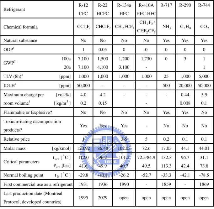
(17) 2.1. Refrigerants and Environment. Table 2.1.1 shows the characteristics of some refrigerants, and from the table the effects on the environment of these refrigerants also can be seen [Halozan and Rieberer, 2000; 張, 1998]. In order to protect the ozone layer, the refrigerant R-12 has been interdicted, and R-22 will be provided against in the future. For this reason, the refrigerants, R-134a and R-410a, are extensively developed in refrigerators and air conditioners. Although there still are not the prohibition against R-134a and R-410a, the high global warming potential, which will increase the global temperature and harm the ecological environment, of these two refrigerants can’t be ignored. The nature refrigerants are considered to replace these refrigerants discussed above [Hwang and Ohadi, 1998], and in the all nature refrigerants, ammonia, hydrocarbons, and carbon dioxide are in common use in the resent day. Ammonia is flammable and toxic, so it is widely used in the industry not suit to be used in the family. Similarly, hydrocarbons is flammable, even though its technique of application is mature, it is still not to be accepted by the market for its safe consideration.. 4.
(18) Refrigerant. R-12. R-22. R-134a. R-410A. CFC. HCFC. HFC. HFC-HFC CH 2 F2 /. R-290. R-744. NH 4. C3H8. CO 2. Chemical formula. CCl 2F2. Natural substance. No. No. No. No. Yes. Yes. Yes. 1. 0.05. 0. 0. 0. 0. 0. 100a. 7,100. 1,500. 1,200. 1,730. 0. 3. 1. 20a. 7,100. 4,100. 3,100. -. [ppm]. 1,000. 1,000. 1,000. 1,000. 25. 1,000. 5,000. [ppm]. 50,000. -. -. -. 500. 20,000. 50,000. [vol-%]. 4.0. 4.2. -. -. -. 0.44. 5.5. [ kg/m 3 ]. 0.2. 0.15. 0.008. 0.1. No. No. No. No. Yes. Yes. No. Yes. Yes. Yes. -. No. No. No. 1. 1. 3-5. 5. 0.2. 0.1. 0.1. [kg/kmol]. 120.92. 86.48. 102.03. 72.6. 17.03. 44.1. 44.01. t crit [ ° C ]. 112.0. 96.2. 101.2. 72.5/84.9. 132.3. 96.7. 31.1. Pcrit [bar]. 41.6. 49.9. 40.7. 49.5. 113.3. 42.4. 73.8. tN [°C ]. -29.8. -40.8. -26.2. -52.7. -33.3. -42.1. -78.5. 1931. 1936. 1990. -. 1859. -. 1869. 1995. 2029. open. open. open. open. open. ODP. 1. GWP2 TLV (8h)3 IDLH. 4. Maximum charge per room volume5 Flammable or Explosive?. Toxic/irritating decomposition products? Relative price Molar mass Critical parameters Normal boiling point. First commercial use as a refrigerant Last production date (Montreal Protocol, developed countries). Table 2.1.1. CHClF2 CH 2 FCF3. R-717. CHF2 CF3. 1. -. Characteristics of some refrigerants (Lorentzen,1995; VDI, 1994). 1. Ozone depletion potential.. 2. Global warming potential in relation to CO 2 with 20 and 100 years integration time.. 3. Threshold limit value: time weight average concentration to which one may be repeatedly exposed for 8 hr per. day or 40 hr per week without adverse effect. 4. Maximum level from which one could escape within 30 minutes without any escape-impairing symptoms or. any irreversible health effects. 5. Maximum refrigerant charge in relation to refrigerated room volume, as suggested in ANSI/ASHREA 15-1989.. 5.
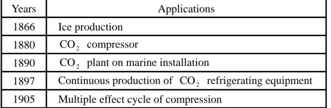
(19) 2.2. CO 2 Refrigerant. CO 2 is a part of the atmosphere, and it is a substance that is not flammable and not. toxic, and the most important of all is that it has no ODP and it offers a negligible GWP. The history of using CO 2 in the refrigeration can be stretched back well over 100 years [Robinson and Groll, 1996]. Although CO 2 refrigerant has many superior properties, the great loss of volume in the high operation temperature, low efficiency, and high operation pressure were the problems could not overcome in the end of the Thirties. Therefore, the CFCs and HCFCs entered the market, and the development of the application products of CO 2 also stopped in the international until 1950 as shown in Table 2.2.1 [張,1998]. Due to the development of science technology with time went by and the requirement for environment protection, it starts to have new researches about the applications of using CO 2 as a refrigerant in air conditioners, and expects that there will be the breakthrough. development for CO 2 refrigerant.. Years. Applications. 1866. Ice production. 1880. CO 2 compressor. 1890. CO 2 plant on marine installation. 1897. Continuous production of CO 2 refrigerating equipment. 1905. Multiple effect cycle of compression. Table 2.2.1. The history of CO 2 as refrigerant. 6.
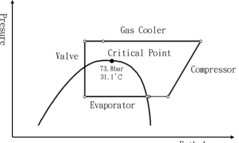
(20) 2.2.1. Advantages of CO 2 Refrigerant. On the performance, the best advantage of CO 2 refrigerant is that the density is much higher than the traditional refrigerants at its high operation pressure and the latent heat of evaporation is higher, too, so the volume flow rate is small in the same cooling capacity compared with other refrigerants, then, decreases the required volume of compressors [Robinson and Groll, 1996]. Besides, the higher heat conduction coefficient gives the better heat conduction effect, and other advantages using CO 2 as a refrigerant list below, 1.. It is non-flammable and non-toxic.. 2.. It is compatible with normal lubricants and construction material.. 3.. The volumetric refrigerating capacity of CO 2 is about 5 times that of R-22.. 4.. It is cheap, plentiful, and there is no need for recovery.. 2.2.2. Issues of CO 2 Refrigerant. The mean factor, which influence the thermodynamic properties of CO 2 , is the critical data of CO 2 , which are about 31 ° C and 74 bar [張,1998], and it will be explained below,. 1.. The critical temperature is 31 ° C , and it is close to the general surrounding temperature, especially in summer. For this reason, when compressing the CO 2 refrigeration, its temperature of the heat release region has to higher than the critical temperature. And the refrigeration cycle will be a transcritical cycle, as shown in Fig. 2.2.1, which means the refrigeration cycle releases heat in the supercritical region and absorbs heat in the subcritical region.. 2.. Because the critical pressure of CO 2 is high, about 73.8 bar, and the refrigeration cycle is a transcritical cycle, the operation pressure will be much higher, about ten 7.
(21) times that of R-22, during the compressing process. According to the high working pressure, there are some problems that have to be more considered when designing compressors using CO 2 refrigerant. Such as that the strength of compressors has to be more considered to support the high pressure, the leakage will become more serious at high pressure, the friction will also increase, and so on. In this study, the main point will put on the strength analysis of compressors, and will consider the performance and the strength together to design compressors.. Fig. 2.2.1 Pressure-enthalpy diagram of CO 2 refrigeration cycle (1). 8.
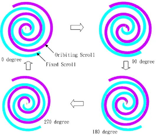
(22) CHAPTER 3. SCROLL COMPRESSOR. Due to the scroll compressor possessing many advantages such as high efficiency, low noise, and high reliability, etc., it becomes more and more popular in refrigeration air conditioner use. According to the awakening to the environmental protection, in this thesis the scroll compressor is used with CO 2 as the refrigerant.. 3.1. Operation Principle. The major structures of scroll compressor include the fixed scroll, orbiting scroll, anti-rotation mechanism, eccentric shaft, and crankcase [Lai and Tseng, 1994]. The fixed scroll and the orbiting scroll are engaged in a manner such that the radius of revolution eccentrically separates the axes of these scrolls from each other. The orbiting scroll is driven by the rotation of the crankshaft that is driven by the motor, transmitted via the revolution during mechanism consisting of eccentric shaft. The orbiting scroll revolves along a circular orbit having a radius of revolution, while rotation of the orbiting scroll is prevented by the anti-rotation mechanism. In this way, the volume of chambers between the fixed scroll and the orbiting scroll, as shown in Fig. 3.2.1, are gradually reduced toward the center, and the working gas is also compressed.. 9.
(23) 3.2. Issues of CO 2 Scroll Compressor. The wraps of scroll compressor contact CO 2 refrigerant directly and it is the important element when considering the strength of scroll compressor. In this thesis, it will use the finite element method to analyze the stress and the deformation of scroll wraps in order to find the optimum dimensions of the scroll wrap.. Fig. 3.2.1 Operation of scroll compressor. 10.
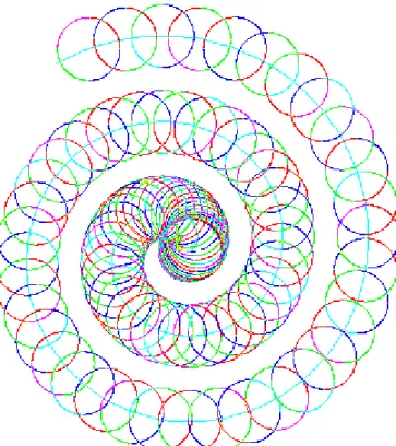
(24) 3.3. Geometric of Scroll Wrap. The three-dimension scroll model for finite element analysis is build from the two-dimension scroll wrap, so it needs to derive the equations of the two-dimension scroll wrap before analyzing [林,2002]. The scroll wrap is generated by the tool cutting along the involute curve as shown in Fig. 3.2.1 and the formulas of the scroll wrap can be derived by using the coordinate transformation rule. The equations derived will be shown below.. Fig. 3.3.1 Generation of scroll wrap. 11.
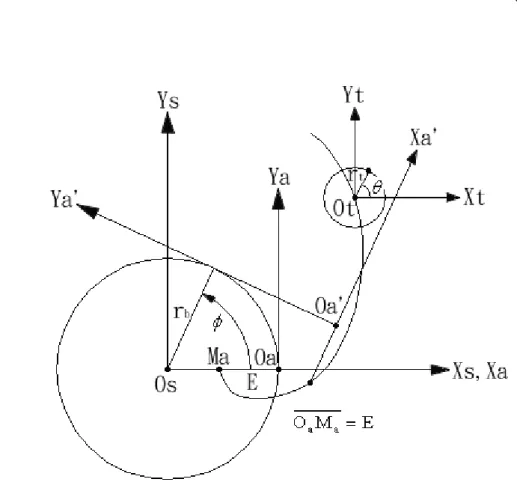
(25) 3.3.1. Extend Involute Curve. An extended involute curve is generated by point M a , where has a small extended interval E with a base circle having the radius rb , besides, the involute angle is φ . As shown in Fig. 3.3.2. Coordinate systems S s ( X s , Ys ) and S a ( X a , Ya ) are the reference and movement coordinate system respectively, and the equations of the extended curve can be derived by the rule of coordinate transformation. The relationship of the position between the origins of coordinates S s and S a can be represented, ⎡Osax ⎤ ⎡rb cos φ + rbφ sin φ ⎤ ⎢O ⎥ = ⎢ ⎥. ⎣ say ⎦ ⎣ rb sin φ − rbφ cos φ ⎦. ( 3.3.1 ). The Ya axis of coordinate system S a is rolling but not slipping on the base circle, and the involute curve is generated by the trajectory of point M a . Equations of the trajectory of point M a can be derived from the matrix equation, R s = M sa × R a ,. ( 3.3.2 ). where the vector R s and R a represent the coordinates of the generated point relates the coordinate systems. S s and. Sa. respectively, and. M sa. represent the coordinate. transformation matrix from S a to S s ,. ⎡− E ⎤ R a = ⎢⎢ 0 ⎥⎥ ⎣⎢ 1 ⎦⎥. ,. ⎡cos φ [M sa ] = ⎢⎢ sin φ ⎢⎣ 0. ( 3.3.3 ) − sin φ cos φ 0. O1ax ⎤ O1ay ⎥⎥ 1 ⎥⎦. .. ( 3.3.4 ). 12.
(26) Then, the equations of extended curve can be solved from Equations ( 3.3.1 ), ( 3.3.2 ), ( 3.3.3 ), and ( 3.3.4 ),. ⎡− E cos φ + rb cos φ + rbφ sin φ ⎤ Rs = ⎢ ⎥ ⎣ − E sin φ + rb sin φ − rbφ cos φ ⎦ .. ( 3.3.5 ). And the standard involute curve will be generated when E is equal to zero,. ⎡r cos φ + rbφ sin φ ⎤ Rs = ⎢ b ⎥ ⎣rb sin φ − rbφ cos φ ⎦ .. ( 3.3.6 ). Fig. 3.3.2 The coordinate system of an extended involute curve. 13.
(27) 3.3.2. Profile of Scroll Wrap. As shown in Fig. 3.3.2, the center of the tool circle moves along the extended involute curve, where the radius of the tool circle is rt , the angle of the tool circle is θ , and the coordinate of any position on the tool circle, relates to the coordinate system of the tool, can be represented as below,. ⎡r cosθ ⎤ Rt = ⎢ t ⎥ ⎣ rt sin θ ⎦ .. ( 3.3.7 ). Then, using the rule of coordinate transformation changes R t to S s , R ts = R s + R t ,. ⎡− E cos φ + rb cos φ + rbφ sin φ + rt cosθ ⎤ R ts = ⎢ ⎥ ⎣ − E sin φ + rb sin φ − rbφ cos φ + rt sin θ ⎦ .. ( 3.3.8 ). In order to solve the relation between φ and θ , the equation of meshing, as shown in Equation ( 3.3.9 ), is used,. n 1 ⋅ V12 = 0 ,. ( 3.3.9 ). where n 1 and V12 represent, respectively, the unit normal vector of the tool circle and the relative velocity of the tool to the fixed coordinate, ⎡− cosθ ⎤ n1 = ⎢ ⎥ ⎣ − sin θ ⎦ ,. ( 3.3.10 ). ⎡ E sin φ + rbφ cos φ ⎤ V12 = −ω ⎢ ⎥ ⎣− E cos φ + rbφ sin φ ⎦ ,. ( 3.3.11 ). where ω is the angle velocity. And the relation between φ and θ can be derived from Equations ( 3.3.9 ), ( 3.3.10 ), and ( 3.3.11 ),. 14.
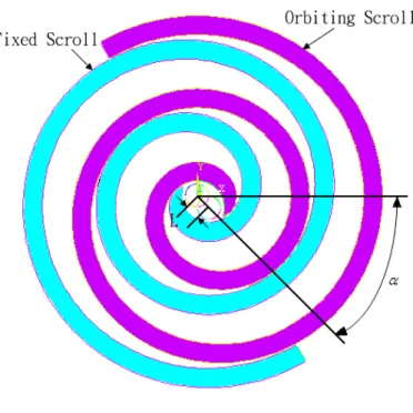
(28) ⎛ rbφ ⎞ ⎟ ⎝ E ⎠.. θ = φ + arctan⎜. ( 3.3.12 ). Then, the outer profile and the inner profile of the fixed scroll can be represented as Equations ( 3.3.13 ) and ( 3.3.14 ),. ⎡− E cos φ + rb cos φ + rbφ sin φ + rt cosθ ⎤ R fo = ⎢ ⎥ ⎣ − E sin φ + rb sin φ − rbφ cos φ + rt sin θ ⎦ , ⎛ rbφ ⎞ ⎟ ⎝ E ⎠,. θ = φ + arctan ⎜. ( 3.3.13 ). ⎡− E cos φ + rb cos φ + rbφ sin φ + rt cos(θ + π )⎤ R fi = ⎢ ⎥ ⎣ − E sin φ + rb sin φ − rbφ cos φ + rt sin θ + π ) ⎦ , ⎛ rbφ ⎞ ⎟ ⎝ E ⎠.. θ = φ + arctan ⎜. ( 3.3.14 ). 3.3.3. Scroll Wrap Pair. The profiles of the fixed scroll are derived from above, and the relationship between the orbiting scroll and the fixed scroll is shown as Fig. 3.3.3 and Fig. 3.3.4. The orbiting scroll generates from the fixed scroll rotating an angle ψ , and then moves an orbiting radius L and a displacement angle α . The profile of the orbiting scroll can be derived from Equation ( 3.3.15 ), R o = M of × R f ,. ( 3.3.15 ). where R o and R f are the positions of the orbiting scroll and the fixed scroll separately, and M of represents the coordinate transformation matrix from the fixed scroll to the orbiting scroll,. 15.
(29) M of. ⎡cosψ = ⎢⎢ sinψ ⎢⎣ 0. − sinψ cosψ 1. L cos α ⎤ L sin α ⎥⎥ 1 ⎥⎦. .. ( 3.3.16 ). Then, the outer profile and the inner profile of the orbiting scroll can be represented as Equations ( 3.3.17 ) and ( 3.3.18 ),. ⎡− E cos(φ + ψ ) + rb cos(φ + ψ ) + rbφ sin(φ + ψ ) + rt cos(φ + ψ ) + L cos α ⎤ Roo = ⎢ ⎥ ⎣ − E sin(φ + ψ ) + rb sin(φ + ψ ) − rbφ cos(φ + ψ ) + rt sin(φ + ψ ) + L sin α ⎦ , ⎛ rbφ ⎞ ⎟ ⎝ E ⎠,. θ = φ + arctan⎜. ( 3.3.17 ). ⎡− E cos(φ + ψ ) + rb cos(φ + ψ ) + rbφ sin(φ + ψ ) − rt cos(φ + ψ ) + L cos α ⎤ Roo = ⎢ ⎥ ⎣ − E sin(φ + ψ ) + rb sin(φ + ψ ) − rbφ cos(φ + ψ ) − rt sin(φ + ψ ) + L sin α ⎦ , ⎛ rbφ ⎞ ⎟ ⎝ E ⎠.. θ = φ + arctan⎜. ( 3.3.18 ). Fig. 3.3.3 Relationship between two scrolls (1). 16.
(30) Fig. 3.3.4 Relationship between two scrolls (2). 3.4. State of Compressed Gas. In this study, the operation of the scroll compressor is assumed that, 1.. The refrigerant is considered as the idea gas.. 2.. The process of compression is an adiabatic and isotropic process.. Besides, CO 2 is taken as the refrigerant, and the compression refrigeration cycle of CO 2 is the transcritical cycle, the state properties in the transcritical region are not expectable, so the process in the condenser is assumed to be a isobaric process, and the process in the expansion valve is assumed to be a iso-enthalpy process. Fig. 2.2.1 shows the refrigeration cycle.. 17.
(31) And the states of compressed gas in compressed chambers can be derived using the polytropic theoretical formula, as following, k. ⎛V ⎞ P = Ps ⎜ s ⎟ ⎝V ⎠ , k −1 k. ⎛P T = Ts ⎜⎜ ⎝ Ps. ⎞ ⎟⎟ ⎠. ⎛P ρ = ρ s ⎜⎜ ⎝ Ps. ⎞ ⎟⎟ , ⎠. ,. ( 3.4.1 ). k. where k is the specific heat ratio, Ps and Ts , are the pressure and the temperature of the suction chamber and all of them can be measured from the experiment, and the suction density ρ s is gotten from the reference about the refrigerant. Moreover, the suction volume Vs can be derive from the Equation ( 3.4.2 ) [吳,1990], Vs = ( 2 N − 1) pπ ( p − 2t ) h ,. ( 3.4.2 ). where N is the number of circles, p is the pitch, t is the thickness, and h is the height of the scroll wrap, and the volume Vi of i th chambers can be derived from the Equation ( 3.4.3 ). Vi = (2i − 1 −. θo ) pπ ( p − 2t )h π. (i ≥ 2 ) ,. ( 3.4.3 ). where i counts from the inner chamber to the outer chamber, and θ o represents the orbiting angle. From the above equations, the state of compressed gas at any orbiting angle all can be derived.. 18.
(32) CHAPTER 4. SIMULATION PROGRAM. As designing a scroll compressor, it always decides a target cooling capacity or other target of scroll compressor performance first, and then, designs the dimensions of scroll wrap to obtain this objective. Following this process, the simulation program will use to obtain the performance of scroll compressors, and using finite element method to analyze wrap strength that will describe later, and then, consider these together to design the scroll wrap.. 4.1. Performance Simulation Program of Scroll Compressor. The “Performance Simulation Program of Scroll Compressor” is offered from the Energy and Resources Laboratories of Industrial Technology Research Institute, and it can calculate the performance of scroll compressor such like EER, refrigeration capacity, volumetric efficiency, mechanical efficiency, and so on. The dimensions of scroll wrap, lubricant properties, motor parameters, and so on, can be used as input data of the program. It has good results for simulating the scroll compressor using R410A or R134a compared with experiments. But now, the refrigerant properties of CO 2 are used, and it is not sure that the simulation results approximate the real situations. In this thesis, the reference [Ishii, 2002] is used to compare with the simulation program and to modify the simulation.. 4.2. Modify the Simulation Program. The reference [Ishii, 2002], “Efficiency Simulations of a Compact CO 2 Scroll Compressor and Its Comparison with Same Cooling Capacity R410A Scroll Compressor,” presents about the efficiency simulation and compares the efficiencies between CO 2 scroll compressor and R410A scroll compressor. Besides, it gives the fixed cooling capacity and 19.
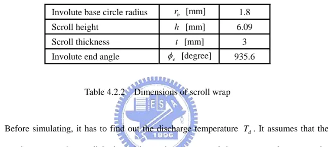
(33) suction volume and regulates base circle radius and scroll height to find the best efficiency. The parameters in [Ishii, 2002], as shown in Table 4.2.1, are clearer to take as the input data in the simulation program to compare each other.. Cooling capacity. [kcal/hr]. 3043. Operating speed. [rpm]. 3498. Involute base circle radius. rb [mm]. 1.4~3.0. Scroll height. h [mm]. 9.7~3.6. Scroll thickness. t [mm]. 3. Cylinder diameter. D [mm]. 67.54. Suction volume. Vs [cc]. 4.25. Volume ratio. 2.07. Pressure ratio. 2.57. Specific heat ratio. 1.3 Ts [°C]. 10.5. Suction pressure. Ps [MPa]. 3.5. Discharge pressure. Pd [MPa]. 9. Axial clearance. δ a [ µm ]. 3. Radial clearance. δ r [ µm ]. 6. Suction temperature. Table 4.2.1 Major specification of scroll compressor in [Ishii, 2002]. According to the result of simulation in [Ishii, 2002], the scroll compressor has the best efficiency when the involute base circle radius rb is 1.8 mm, and the scroll wrap height h is about 6.09 mm. And the other parameters can be calculated under Table 4.2.1 and following equations, p = 2πrb ,. ( 4.2.1 ). ro = rbπ − t ,. ( 4.2.2 ) 2. ⎛ D − ro ⎞ t ⎟⎟ − 1 − φ e = ⎜⎜ rb ⎝ 2rb ⎠ ,. ( 4.2.3 ) 20.
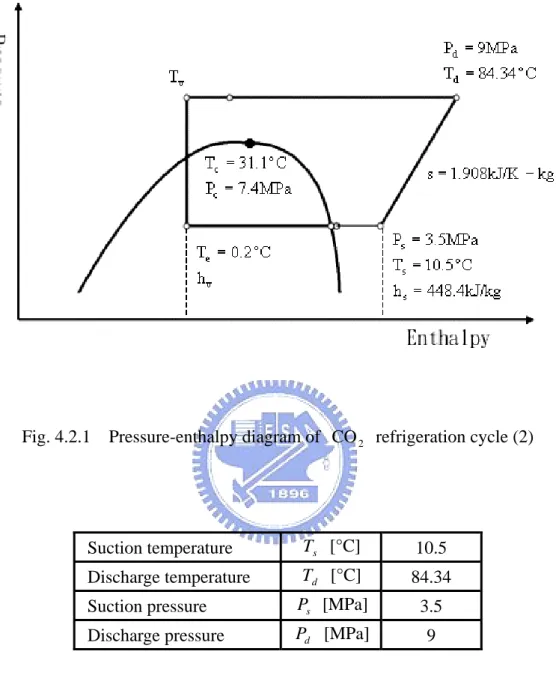
(34) ⎛ ⎝. 1⎞ 4⎠,. φ e = 2π ⎜ N + ⎟. ( 4.2.4 ). Vs = (2 N − 1)πhp( p − 2t ) .. ( 4.2.5 ). The dimensions of scroll wrap can be derived as shown in Table 4.2.2, and these dimensions will be used to simulate the efficiencies of CO 2 scroll compressor using simulation program to compare with that in [Ishii, 2002].. Involute base circle radius. rb [mm]. 1.8. Scroll height. h [mm]. 6.09. Scroll thickness. t [mm]. 3. φ e [degree]. 935.6. Involute end angle. Table 4.2.2 Dimensions of scroll wrap. Before simulating, it has to find out the discharge temperature Td . It assumes that the compression process is an adiabatic and isotropic process, and the entropy value s can be derived from given Ts and given Ps by check the pressure-enthalpy diagram for refrigerant 744 (carbon dioxide). In order to calculate the status data of many refrigerants at any status, the software called NIST is used, and the database of the software bases on the National Institute of Standards and Technology. Using NIST, the entropy value s and discharge temperature Td can be derived easily, and the refrigeration cycle is shown in Fig. 4.2.1, and the suction and discharge states of CO 2 are shown in Table 4.2.3.. 21.
(35) Fig. 4.2.1 Pressure-enthalpy diagram of CO 2 refrigeration cycle (2). Suction temperature. Ts [°C]. 10.5. Discharge temperature. Td [°C]. 84.34. Suction pressure. Ps [MPa]. 3.5. Discharge pressure. Pd [MPa]. 9. Table 4.2.3 The suction and discharge states of CO 2. In order to find out the temperature at expansion valve inlet Tv , the fixed cooling capacity at 3043 kcal/hr is considered. From the following equations, Qc = Gr ⋅ (hs − hv ) ,. ( 4.2.6 ). Gr = η v ⋅ (Vs ⋅ ρ s ⋅ ω m ) ,. ( 4.2.7 ). 22.
(36) where the density of suction refrigerant ρ s is about 87.56 kg/m3 which can be obtained from NIST, the enthalpy at compressor inlet hs is about 448.4 kJ/kg obtained from NIST, too, and if the volumetric loss is neglect, the refrigerant flow rate can be shown as below,. ′ Gr = Vs ⋅ ρ s ⋅ ω m .. ( 4.2.8 ). From above equations, the enthalpy at expansion valve inlet hv can be derived, which is about 264.6 kJ/kg. Then the temperature at expansion valve inlet Tv can be obtained from NIST, which is about 26.6 °C. The input data of the simulation program are listed in Table 4.2.4, and the other input data like other scroll parameters which is not shown in Table 4.2.4, friction coefficient, Oldham parameters, and so on, are not changed.. Scroll thickness. t [mm]. 3. Scroll pitch. p [mm]. 11.3. Scroll height. h [mm]. 6.09. φ e [degree]. 935.6. Axial clearance. δ a [ µm ]. 0. Radial clearance. δ r [ µm ]. 6. Discharge pressure. Pd [MPa]. 9. Temperature at evaporator. Te [°C]. 0.2. Suction temperature. Ts [°C]. 10.5. Temperature at expansion valve inlet. Tv [°C]. 26.6. Involute end angle. Table 4.2.4 Input data of the simulation program. 23.
(37) 4.3. Results and Discussions. Because leakage has big influence on volumetric efficiency, especially the axial leakage, the axial leakage is considered to be zero where the radial leakage maintains to be 6 µm to compare the result of [Ishii, 2002] with the result of program. In [Ishii, 2002], the volumetric efficiency is about 96 %, then using the same parameters and fixing the cooling capacity at 3043 kcal/hr, the volumetric efficiency from the simulation program is about 90.18 % wherein the cooling capacity is about 3026.4 kcal/hr. The volumetric efficiency about 96 % is difficult to achieve for the volumetric loss caused by the suction over heat may happen actually, and the simulation in [Ishii, 2002] may not consider this in its simulation program, so it can get higher volumetric efficiency. In order to check the accuracy of the simulation program offered from the Industrial Technology Research Institute, a prototype is planed to be built which bases on the scroll compressor system for R410A and its refrigeration cycle is based on the product of heat pump water heater of Sanyo wherein the rotary compressor of two-stage compression type and the CO 2 refrigerant are used and is planed be changed with the prototype of scroll compressor. The operation pressure using CO 2 refrigerant is higher than using R410A refrigerant, it needs to check the strength of scroll wrap bases on the R410A scroll compressor system first. In this thesis, the finite element analysis is used to do the strength analysis of scroll warp. And then, the strength of scroll wrap and the operation efficiency of scroll compressor are all taken into account to design the optimum dimensions of scroll compressor.. 24.
(38) CHAPTER 5. FINITE ELEMENT METHOD. In this study, the ANSYS software is used for finite element analysis. The ANSYS is widely used for finite element analysis, which was developed by Dr. John Swanson from 1953 [蔡,2003]. This software was used for solid mechanics analysis at first, but it extends to solve the problems about hydrodynamics, impact, electromagnetic analysis, heat conduction, and so on, to this day.. 5.1. ANSYS Parametric Design Language. The ANSYS Parametric Design Language, called “APDL” after, is a useful tool of ANSYS. The functions of APDL are that, 1.. Redo the work others have done.. 2.. To do special calculations that ANSYS do not provide.. 3.. Require many commands for an analysis.. And APDL includes some characteristics that, 1.. Parameterize.. 2.. Using macros.. 3.. Vector or matrix operations. 4.. Subprograms created by users.. 5.. “IF” and “DO” loop operations.. In this study, APDL is used to create the analysis models of scroll wrap based on the equations of scroll wrap profile, in order to create analysis models easily in other dimensions and save time to do analysis in different situation.. 25.
(39) 5.2. Scroll Compressor Structure. In this study, the scroll compressor structure for analyzing scroll strength is based on the present products of scroll compressor using R410A refrigerant, and the assembly figure of scroll compressor structure is shown in Fig. 5.2.1 [賴,1998]. And the common dimensions of the fixed scroll and the orbiting scroll may be the design parameters to get enough strength when the refrigerant is changed to CO 2 refrigerant. In the analysis model, the constraint conditions of the scroll component can be got according to the assembly relation of scroll compressor structure.. Fig. 5.2.1 Assembly relation of scroll compressor structure [賴,1998] 26.
(40) 5.3. Refrigeration Cycle. A product of CO 2 heat pump water heater made by Sanyo is considered to change its rotary compressor to scroll compressor. The temperatures of refrigerant cycle of the CO 2 heat pump water heater are measured from the Industrial Technology Research Institute, and the partial data are shown in Table 5.3.1. And using the NIST, the refrigeration cycle can be shown in Fig. 5.3.1. The data of refrigeration cycle are the thermal parameter input of performance simulation program of scroll compressor to get the pressure of each compression chamber.. Suction temperature. Ts [°C]. 20. Discharge temperature. Td [°C]. 94.88. Temperature at evaporator. Te [°C]. 26.36. Temperature at expansion valve inlet. Tv [°C]. 12.25. Table 5.3.1 Temperatures of refrigerant cycle. Fig. 5.3.1 Pressure-enthalpy diagram of CO 2 refrigeration cycle (3) 27.
(41) 5.4. Scroll Model. The scroll wrap is generated by the tool cutting along the involute curve, and the formulas of the scroll wrap can be derived by using the coordinate transformation rule, seeing in CHAPTER 3, where the standard involute curve is used. And the dimensions of scroll wrap of the scroll compressor using R410A refrigerant are list in Table 5.4.1.. Scroll thickness. t [mm]. 2.7. Scroll pitch. p [mm]. 11.4. Scroll height. h [mm]. 12.3. Involute end angle. φ e [degree]. 980. Discharge start angle. θ d [degree]. 63.44. Table 5.4.1 Dimensions of scroll wrap of the scroll compressor for R410A. Because the major stress happens on the orbiting scroll at the discharge start angle [賴, 1998], the orbiting scroll at the discharge start angle is taken to do the finite element analysis, and the mesh model of orbiting scroll is shown in Fig. 5.4.2. The mesh element is SOLID45 which has eight nodes and is used to simulate the 3-D solid structure as shown in Fig. 5.4.1 [陳,2002].. Fig. 5.4.1 SOLID45 3-D structural solid 28.
(42) 1 ELEMENTS. Fig. 5.4.2 Mesh model of orbiting scroll. 5.4.1. Material Properties. The mean material of scroll is cast iron presently, because the cast iron has some advantages that good strength, hard-wearing, good lubricity, and so on. In this study, the cast iron is used, and its properties are shown in Table 5.4.2.. Young’s modulus [N/ m 2 ] Possion’s ratio. 6.62 × 10¹⁰ 0.27. 3. Density [kg/ m ]. 7200. Tensile strength [N/ mm 2 ]. 230. Table 5.4.2 Properties of cast iron. 29.
(43) 5.4.2. Boundary Conditions. After building the scroll model, it needs to give the boundary conditions of the scroll model to conform the scroll model to actual situation of scroll element possibly when the scroll compressor operates. The boundary conditions include the pressure that CO 2 refrigerant applies on the scroll component and the constraint conditions in this study.. A. Pressure Field The pressure in each compression chamber at different orbiting angle can obtain from the performance simulation program of scroll compressor, and the compression chambers are in order from the inner chamber to the outer chamber [吳,1990], as shown in Fig. 5.4.3, where the inner chamber is the first chamber. Besides the surfaces of the compression chambers, the other surfaces of the scroll model are applied the suction pressure of scroll compressor.. Fig. 5.4.3 Compression chambers of scroll compressor 30.
(44) B. Constraint conditions The constraint conditions are considered form the assembly relation of scroll compressor structure as shown in Fig. 5.2.1 to get more reasonable and actual analysis result. In this thesis, an annular thrust element is positioned on the bottom of the scroll element and its center is coincident with the coordinate center of the fixed scroll that means that the annular thrust element has an orbiting radius and orbiting angle shift with the orbiting scroll. The constraint conditions apply on the bottom of the thrust element where the degrees of freedom are all fixed as shown in Fig. 5.4.4.. Fig. 5.4.4 Constraint conditions of orbiting scroll. 31.
(45) 5.5. Analysis and Results. The initial scroll model of finite element analysis combines the dimensions of scroll compressor using R410A refrigerant from present product with the compression refrigeration cycle of heat pump water heater using CO 2 as refrigerant. The parameters of the scroll model and the refrigeration cycle are talked above. The stress distribution of the orbiting scroll is shown in Fig. 5.5.1, and the compressor performance simulation results and the analysis results list in Table 5.5.1 where EER, the energy efficiency ratio, and the cooling capacity are taken as the target of the scroll compressor performance and the safety factor is the target of strength of the orbiting scroll. The maximum von mises stress happens on the top of the second circles of scroll wrap not on the bottom of the second circles of scroll wrap. It is because that when the pressure field is given on the surface of scroll wrap and if the curvature of the scroll wrap is large, taking a section of cambered surface of scroll wrap into consideration, the opposite forces paralleled the base plate on the two sides of the cambered surface will bigger than the curvature of the scroll wrap is small that will cause the stress concentration on the top of the scroll wrap which maybe larger than the stress concentration on the bottom of the scroll wrap. So, it is possible that the maximum von mises stress happens on the top of the second circles of scroll wrap.. 32.
(46) NODAL SOLUTION STEP=1 SUB =1 TIME=1 SEQV (AVG) PowerGraphics EFACET=1 AVRES=Mat DMX =.029028 SMN =.010182 SMX =89.309 .010182 9.932 19.854 29.777 39.699 49.621 59.543 69.465 79.387 89.309 .010182 9.932 19.854 29.777 39.699 59.543 69.465 79.387 89.309. 1. 2. Fig. 5.5.1 Stress distribution of orbiting scroll. EER [kcal/hr-W]. 2.01. Cooling capacity [kcal/hr]. 8850.34. Max. von mises stress [MPa]. 89.309. Max. deformation [ µm ]. 27.192. Safety factor. 2.58. Table 5.5.1 Analysis results of orbiting scroll. 33.
(47) Because the safety factor of the orbiting scroll in the scroll compressor using R410A is 4.48 [賴,1998], that safety factor is used in this study. From the Table 5.5.1, the safety factor of orbiting scroll in the same dimension of scroll compressor but using CO 2 as refrigerant is 2.58 less than 4.48, it means that the orbiting scroll in that dimension of orbiting scroll is not strong enough and it may yield when the scroll compressor is working. Some parameters of the scroll compressor may be changed to make the orbiting scroll stronger, for instance, the shorter scroll wrap or thicker scroll wrap or bath all them can increase the strength of the scroll wrap. At first, the height of scroll wrap and the discharge are respectively changed for performance simulation and finite element analysis. There are detailed description in the below section.. A. Different Scroll Wrap Height The initial scroll model is based on the present R410A scroll compressor, and it planes to use this R410A scroll compressor structure to create the prototype of the CO 2 scroll compressor in the future. The height of scroll wrap is easy to change basing on the present product, so it is chosen to be the first considerable variable to increase the strength of orbiting scroll. The tendency of EER and safety factor in different scroll wrap height is shown in Fig. 5.5.2. The safety factor increases with the height of scroll wrap decrease as expectancy, but the EER decreases with the height of scroll wrap decreases. It can see that when the safety factor is over than 4.48, the EER is down to less than 1.4 that means the performance of the scroll compressor is very pool.. 34.
(48) Fig. 5.5.2 EER and safety factor versus scroll wrap height. B. Different Discharge Pressure The deformation and stress of scroll wrap are caused by the pressure difference between the compression chambers. Decreasing the difference between the suction pressure and the discharge pressure may reduce the deformation and stress of scroll wrap, and it can separate the pressure difference into two parts using the two-stage compression. In this analysis, the suction pressure of compressor is fixed, and the discharge pressure is changed to reduce the pressure difference. The tendency of safety factor and the EER at different discharge pressure are shown in Fig. 5.5.3. It can find that the EER is getting better with the discharge pressure decreasing, but the safety factor is getting worse which is out of expectation. In usual case, the maximum stress is caused by the difference between the second chamber and the third chamber where the chambers defining is shown in Fig. 5.4.3, 35.
(49) but when the discharge pressure decreases in this analysis, although the pressure difference between the second chamber and the third chamber reduces, the pressure difference between the first chamber and the second chamber increases as shown in Fig. 5.5.4. It causes that the maximum stress happens on the central scroll wrap not on the second circles of wrap. Because for the same scroll profile the shape design compression ratio does not change, but the T.E.C design compression ratio decreases, and the over compression will happen. It may need to design a new scroll profile or an earlier discharge start angle to solve this problem.. Fig. 5.5.3 EER and safety factor versus discharge pressure. 36.
(50) Fig. 5.5.4 Pressure difference between chambers versus discharge pressure. Fig. 5.5.5 Pressure difference between chambers versus scroll wrap height. 37.
(51) 5.6. Discussions. From the above analysis results, in order to get the better EER, the most efficacious way is to decrease the pressure difference between the suction pressure and the discharge pressure of scroll compressor, in above analysis, the suction pressure is fixed and only to change the discharge pressure to reduce the pressure difference. Because the wasted work of friction between the fixed scroll and the orbiting scroll, the orbiting scroll and the thrust bearing, and so on, is reduced greatly for the pressure difference between the suction pressure and the discharge pressure of scroll compressor reduced, it can get better EER. But decreasing the discharge pressure will cause the safety factor of scroll wrap not enough for the pressure difference between the first and the second chambers is increase, even though the pressure difference between the second and the third chambers is reduce. On the other hand, although reducing the scroll wrap height will reduce the EER, it also can improve the safety factor of scroll wrap. Besides, seeing Fig. 5.5.5, the pressure difference between the first and the second chambers is decreased. From the relations between EER and safety factor versus the discharge pressure and the scroll wrap height, in the next chapter, the scroll wrap height, the scroll wrap thickness, and the compression ratio are all considered as the design variables in the optimum design problem to get the best energy efficiency ratio.. 38.
(52) CHAPTER 6. OPTIMUM DESIGN. From the initial analysis results in chapter 5, it is not enough to change only one parameter whether the scroll wrap height or the discharge pressure of scroll compressor to get both enough safety factor and the better EER. The safety factor and EER have opposite tendency relates to the different scroll wrap height and the discharge pressure respectively, and this characteristic can be used to produce a design problem for optimization. The optimum design problem of scroll compressor is described below, and the design variables, definition of the cost function, and the constraints of the system are also included.. 6.1. Design Problem. In this thesis, the performance of the scroll compressor and the strength of the scroll wrap are all taken into the considerations to design a scroll compressor which using CO 2 refrigerant. The performance simulation program of scroll compressor said in CHAPTER 4 is used to get the efficiency of the scroll compressor, and the strength of the scroll wrap is got from the finite element analysis described in CHAPTER 5. The definition of the design variables, cost function, and design constraints are detailed explained in the following statement.. 6.1.1. Design Variables. The scroll wrap height h and the scroll wrap thickness t play important roles on machining rigidity of scroll wrap, so the rigidity factor of scroll wrap (h/t) and the scroll wrap height t are chosen as the design variables to decide the dimensions of scroll wrap. The rigidity of scroll wrap means the acceptability of scroll wrap to prevent the stress damage 39.
(53) when the scroll compressor operates. From the results of finite element analysis for different scroll wrap height seeing in Fig. 5.5.2, when the scroll wrap height is 5 mm and the scroll wrap thickness is 2.7 mm, the safety factor is 4.68 over than 4.48 where the (h/t) is 1.85, and if the scroll wrap height is less then 5 mm at the same scroll wrap thickness, the safety factor will less than 4.48. The safety factor 4.48 is defined from the previous finite element analysis results of R410A scroll compressor [賴,1998]. The rigidity factor of scroll wrap (h/t) and the scroll wrap thickness t are taken as the design variables for the strength of scroll wrap, and their design data for performance simulation and finite element analysis are list in Table 6.1.1.. Rigidity factor of scroll wrap, h/t. 2.5. 3. 3.5. 4. Scroll wrap thickness, t [mm]. 1.5. 2. 2.5. 3. Compression ratio, Pd/Ps. 1.7. 1.9. 2.1. 2.3. 3.5. Table 6.1.1 Design data of design variables. At the initial dimensions of scroll wrap where the scroll wrap height is 12.3 mm, the energy efficiency ratio EER is 2.01 kcal/hr-W, but the EER decreases to 1.38 kcal/hr-W with the scroll wrap height decreases to 5 mm to make the safety factor over than 4.48 as Fig. 5.5.2 shows. In order to improve the EER, the another design variable, compression ratio Pd/Ps, is chosen where the suction pressure of scroll compressor Ps is fixed and only change the discharge pressure of scroll compressor Pd to get different compression ratio as Fig. 5.5.3 shows. The design data of compression ratio are list in Table 6.1.1. Although the design of compression ratio can improve the energy efficiency ratio, the increasing pressure difference between the first chamber and the second chamber may cause the damage of scroll wrap as shown in Fig. 5.5.4. This problem may be solved by the dimension design of scroll wrap, seeing the Fig. 5.5.5, the pressure difference between the 40.
(54) first chamber and the second chamber decreases with the scroll wrap height decreases. In this optimum design, there are three design variables, rigidity factor of scroll wrap h/t, scroll wrap thickness t, and compression ratio Pd/Ps. And the rigidity factor of scroll wrap has four design data, scroll wrap thickness has five design data, and compression ratio has four design data, all data list in Table 6.1.1. There are eighty design combinations for this optimum design problem to fine optimum combination of design variables.. 6.1.2. Cost Function. In this design problem, the performance of scroll compressor and the strength of scroll wrap are all taken in consideration. But it does not need the best strength of scroll wrap, the strength of scroll wrap is taken as the design constraint conditions that will be detailed described in the next statement. The best performance of scroll compressor is considered when design a scroll compressor, and the energy efficiency ratio EER is the main target for the performance of scroll compressor where the energy efficiency ratio EER is the ratio of the cooling capacity to the motor input power. The cost function is the maximum energy efficiency ratio EER. It means to find the best energy efficiency ratio from the eighty design combinations of design variables, and it can be simply expressed in the following form: min - EER( x) ,. where x is design variable set indicated in the preceding section, and the energy efficiency ratio can be got from the performance simulation program of scroll compressor.. 41.
(55) 6.1.3. Design Constraints. The design has to satisfy various performance and technological constraints, such as manufacturing, structure failure, efficiency considerations, and so on. The details are described below: 1.. Safety factor of scroll wrap: the safety factor of scroll wrap is main target of the strength of scroll wrap. In the previous finite element analysis of R410A scroll compressor, the safety factor of the orbiting scroll is 4.48 [賴,1998], and it is taken as the design constraint in the study. The constraint can be described as Safety factor ≥ 4.48 .. 2.. Cooling capacity: there is a range of the cooling capacity, the larger or smaller cooling capacity is not good for the scroll compressor. When designing the scroll compressor, it first has to conform to the needed cooling capacity, and then derive the other design parameters of scroll compressor under that cooling capacity. The range of cooling capacity is presented below: Cooling capacity: 3000~4000 kcal/hr.. 3.. Stiffness of milling tool: stiffness of milling tool is defined by the diameter of the milling tool d T and the height of the milling tool hT , and the ratio of the height of the milling tool to the diameter of the milling tool hT / d T is suitable within 2.5 [Lai and Tseng, 1994]. And the diameter of the milling tool d T is limited by the width of trough of scroll described below: dT ≤ ( p − t ) ,. and the scroll wrap height can substitute for the height of the milling tool hT . The constraint of stiffness of milling tool can be described as. 42.
(56) h ≤ 2.5 . p −t. The pitch of scroll wrap here is fixed at 11.4 mm, and the design data of the design variables list in Table 6.1.1 are selected under this constraint of stiffness of milling tool. 4.. Diameter of base plate: the diameter of base plate may greater than the maximum diameter of scroll wrap so that the scroll wrap can place on the base plate. The pitch of scroll wrap is fixed in this design problem, and the involute end angle is also fixed, so the diameter of base plate may not change in this design problem.. From above statement, the safety factor and the cooling capacity are considered in the optimum design procedure.. 6.1.4. Design Flow Chart. The optimum design flow chart is shown in Fig. 6.1.1. First, the design data of design variables are taken as the input data of the performance simulation program of scroll compressor to get the energy efficiency ratio and the cooling capacity of various combinations of design variables, and then fine out the combinations of design variables that their cooling capacity is between 3000 kcal/hr and 4000 kcal/hr. These selected combinations of design variables then are taken to do the finite element analysis, and then the constraint condition of safety factor is considered, and it can find out the combinations of design variables fit the design constraints. Finally, from the second selected combinations of design variables, the optimum combination of design variables having the best EER can be found.. 43.
(57) INPUT 80 combinations of design variables. ANALYSIS Performance simulation program of scroll compressor. GET Cooling capacity EER. CONSTRAINT 1 Cooling capacity 3000~4000 kcal/hr. INPUT Design variables satisfy CONSTRAINT 1. ANALYSIS Finite element analysis. GET Safety factor. CONSTRAINT 2 Safety factor ≥ 4.48. COST FUNCTION Max. EER. OPTIMUM DESIGN. Fig. 6.1.1 Optimum design flow chart. 44.
(58) 6.2. Results and Discussions. From the design procedure described before, the combinations of design variables which satisfy the design constraints including the safety factor and the cooling capacity are shown in Fig. 6.2.2. The optimum design is that the compression ratio is 1.7, the rigidity factor of scroll wrap is 2, and the thickness of scroll wrap is 3.5 mm, and its EER is 2.76 kcal/hr-W. Fig. 6.2.1 shows the safety factors of the design variables which satisfy the constraint range of cooling capacity. It can find that whether the compressor ratio is different, the feasible combinations of design variable are located at the same region where the rigidity factor of scroll wrap (h/t) places at 2 and 2.5, and the thickness of scroll wrap places at 2.5 mm, 3 mm, and 3.5 mm when the rigidity factor of scroll wrap (h/t) is 2, and the thickness of scroll wrap places at 4 mm when the rigidity factor of scroll wrap (h/t) is 2.5. The tendency of safety factor has great variation when the pressure ratio is less than 1.9, and it can separate into two parts, the high pressure ratio and the low pressure ratio. The curves of high pressure ratio where the pressure ratio are 2.3 and 2.1 are smoother, and the safety factor increases with the pressure ratio decreases. The variation of curves of low pressure ratio where the pressure ratio are 1.9 and 1.7 is violent, and the safety factor decreases with the pressure ratio increases which is opposite to the high pressure ratio curves. It may ascribe this situation to that the pressure difference between the first compression chamber and the second compression chamber is increased when the pressure ratio decreases at the same suction pressure, and it cause the big damage on the inner scroll wrap which described in the CHAPTER 5. Fig. 6.2.2 shows the EER of the design variables which satisfy bath the constraint ranges of cooling capacity and safety factor. It is obvious to see that although the feasible combinations of design variable are located at the same region versus the different 45.
(59) compression ratio, the EER has a difference between the various compression ratios, and the EER increases with the compression ratio decreases. One of the issues of using CO 2 as the refrigerant is the great pressure difference between the suction pressure and the discharge pressure of scroll compressor, and according to the results of optimum design shows in Fig. 6.2.2, the greater compressor ratio at the same suction pressure means the greater pressure difference has more poor EER even it can find the feasible dimensions of scroll wrap having enough strength. Therefore, in order to compress the great pressure difference, it may need to design the scroll compressor of two-stage compression to get the higher EER. From now, there are a few patents about the scroll compressor of two-stage compression, but no product of the scroll compressor of two-stage compression on the business situations even the CO 2 scroll compressor.. 46.
(60) Fig. 6.2.1 Results of optimum design, scroll wrap thickness vs. safety factor. Fig. 6.2.2 Results of optimum design, scroll wrap thickness vs. EER 47.
(61) CHAPTER 7. CONCEPT DESIGN OF SCROLL COMPRESSOR OF TWO-STAGE COMPRESSION TYPE. The working pressure using CO 2 as refrigerant is about 10 times than that using R410A. The scroll wrap could not support at that high working pressure and also has good energy efficiency ratio, so it may design the refrigeration cycle of two-stage compression type to decrease pressure difference between the suction pressure and the discharge pressure of scroll compressor at each compression stage to reduce the damage on the scroll wrap, and also the energy efficiency ratio is not bad which may over 3. The patents about the scroll compressor of the two-stage compression type are introduced in this chapter, and then there is a concept design of the scroll compressor of two-stage compression type offered.. 7.1. Patents Review. There are only a few patents about the scroll compressor of the two-stage compression type, and they can be classified into two kinds according to their structures approximately.. A. Various scroll wrap heights In this structure type of scroll compressor, the scroll wrap has constant thickness and pitch, and the fixed involute wrap and orbiting involute wrap each have at least a first section of one height and a second section of a second different height as Fig. 7.1.1 shows. The pressure ratios of the inner and outer sections of the compressors are independent of each other, and are determined by the number of scroll wraps in each section. The only requirement is that the discharge pressure of the outer section be equal to the inlet pressure of 48.
(62) the inner section. Because the compression stages are formed via the various heights of scroll wrap, and the manufacture of the scroll wrap may have high accuracy, especially the contact place between the different scroll wrap heights to avoid the leakage of working fluid.. Fig. 7.1.1 Sectional view of scroll compressor of US6,050,792. B. Multi-scrolls There are only two scrolls including one fixed scroll and one orbiting scroll in the scroll compressor generally. In order to get another compression stage, it may add other scroll to achieve the objective likes Fig. 7.1.2 shows. The scroll compressor has first, second and third scrolls. The second and third scrolls each have an involute wrap on the base plate and the first scroll has two involute wraps on opposite sides of the base plate. A lower stage compression 49.
(63) part is defined between the first and second scrolls and a higher stage compression part is defined between the first and third scrolls. In this structure type of the two-stage compression scroll compressor, the major design points are about the connection passage that the working fluid can flow from one to the other stage compression part and the transmission device to drive the orbiting scroll. For examples, in the U.S. patent 5,304,047 shows in Fig. 7.1.2, the working fluid flows into the first compression stage from the suction port 33 then discharges to the internal space 13 from the discharge port 34, and the second compression stage has an inlet at the suction port 43 and a outlet at the discharge port 44. An another structure of scrolls, U.S. patent 5,624,247, is shown in Fig. 7.1.4 where the flowing path of working fluid is drawn in from the first-stage intake opening 36 flows through the first-stage delivery opening 36a and is cooled by an intermediate cooler 47, from which it is again drawn into the second-stage intake opening 36b and discharges from the second-stage delivery opening 37. The eccentric drive shafts and cranks of these two structures are placed on the central scrolls to drive scrolls and may pass through the scroll wraps, so these scroll wraps are cut off the central part to contain the eccentric drive shafts or cranks as shown in Fig. 7.1.3. For this reason, the involute end angle of the scroll wrap may increase to get needed compression ratio, and the scroll size is bigger relatively.. 50.
(64) Fig. 7.1.2 Sectional view of scroll compressor of US5,304,047. Fig. 7.1.3 Cross-sectional view of the lower-stage compression part of the scroll compressor of Fig. 7.1.2 51.
(65) Fig. 7.1.4 Sectional view of scroll compressor of US5,624,247. 52.
(66) 7.2. Concept Design. After reviewing the patents about the scroll compressors of two-stage compression type, there is a concept design offered in this study and the sectional view of concept design in part section of scroll compressor is shown in Fig. 7.2.1.. Fig. 7.2.1 Concept design of a two-stage compression scroll compressor. There is a pair of fixed scroll and orbiting scroll in this design to compress the different stage compression individually and the first and second fixed scroll are fastened together on the housing. The back surface of the first fixed scroll has two circular troughs with two different diameters. One of the circular trough is formed a middle pressure space with the back surface of the second orbiting scroll where the middle pressure refrigerant is discharged to from the first discharge port posited on the base plate of the first fixed scroll. The other 53.
(67) circular trough is used to place the second orbiting scroll. The main shaft is contained in the boss of the first orbiting scroll to drive the first orbiting scroll orbits the first fixed scroll. There are at least two idler cranks place though the first fixed scroll, the first fixed scroll, and the second orbiting scroll and connect with those scrolls by the bearings that the cranks can self-rotate relate to the scrolls. The first orbiting scroll is driven by the main shaft and the idler cranks are rotated with the first orbiting scroll operating and then the second orbiting is driven. The refrigerant flows into the compressor from the inlet passage and draws into first compression stage form the first suction port placed on the base plate of the first orbiting scroll and then the compressed refrigerant discharges into the middle pressure space form the first discharge port. Then the compressed refrigerant get into second compression through the second suction port placed on the base plate of the second orbiting scroll and discharges to high pressure space from the second discharge port. The two-stage compression is completed through this process. This structure is closed together and it may cause little vibration, but the mechanical efficiency using the idler cranks to drive the second orbiting scroll may be not better than driven by the main shaft directly.. 54.
數據
+7
![Table 4.2.1 Major specification of scroll compressor in [Ishii, 2002]](https://thumb-ap.123doks.com/thumbv2/9libinfo/8060259.162933/33.892.229.663.267.715/table-major-specification-scroll-compressor-ishii.webp)
相關文件
了⼀一個方案,用以尋找滿足 Calabi 方程的空 間,這些空間現在通稱為 Calabi-Yau 空間。.
Let f being a Morse function on a smooth compact manifold M (In his paper, the result can be generalized to non-compact cases in certain ways, but we assume the compactness
To stimulate creativity, smart learning, critical thinking and logical reasoning in students, drama and arts play a pivotal role in the..
Building on the strengths of students and considering their future learning needs, plan for a Junior Secondary English Language curriculum to gear students towards the learning
Promote project learning, mathematical modeling, and problem-based learning to strengthen the ability to integrate and apply knowledge and skills, and make. calculated
Building on the strengths of students and considering their future learning needs, plan for a Junior Secondary English Language curriculum to gear students towards the
Language Curriculum: (I) Reading and Listening Skills (Re-run) 2 30 3 hr 2 Workshop on the Language Arts Modules: Learning English. through Popular Culture (Re-run) 2 30
Wang, Solving pseudomonotone variational inequalities and pseudocon- vex optimization problems using the projection neural network, IEEE Transactions on Neural Networks 17
