國 立 交 通 大 學
電子工程學系 電子研究所碩士班
碩 士 論 文
以
以
以
以 ZrO
ZrO
ZrO
ZrO
2222和聚合物做為 ISFET/REFET
和聚合物做為
和聚合物做為
和聚合物做為
ISFET/REFET
ISFET/REFET
ISFET/REFET 之感測材料應用於讀出電
之感測材料應用於讀出電
之感測材料應用於讀出電
之感測材料應用於讀出電
路設計之特性與考量研究
路設計之特性與考量研究
路設計之特性與考量研究
路設計之特性與考量研究
The study of characteristics and considerations of ZrO
2and
polymer as ISFETs and REFETs sensing materials for the
application of the readout circuits design
研 究 生: 詹 仲 逸
指導教授: 張 國 明 博士
以
以
以
以 ZrO
ZrO
ZrO
ZrO
2222和聚合物做為 ISFET/REFET
和聚合物做為
和聚合物做為
和聚合物做為
ISFET/REFET
ISFET/REFET
ISFET/REFET 之感測材料應用於讀出電
之感測材料應用於讀出電
之感測材料應用於讀出電
之感測材料應用於讀出電
路設計之特性與考量研究
路設計之特性與考量研究
路設計之特性與考量研究
路設計之特性與考量研究
The study of characteristics and considerations of ZrO
2and
polymer as ISFETs and REFETs sensing materials for the
application of the readout circuits design
研 究 生:詹仲逸 Student:Chung-Yi Chan
指導教授:張國明 博士 Advisor:Dr. Kow-Ming Chang
國 立 交 通 大 學
電子工程學系 電子研究所碩士班
碩 士 論 文
A Thesis
Submitted to Department of Electronics Engineering & Institute of Electronics College of Electrical Engineering and Computer Engineering
National Chiao Tung University In Partial Fulfillment of the Requirements
For the Degree of Master In Electronics Engineering August 2009 Hsinchu, Taiwan
中華民國九十八年八月
以
以
以
以 ZrO
ZrO
ZrO
ZrO
2222和聚合物做為 ISFET/REFET
和聚合物做為
和聚合物做為
和聚合物做為
ISFET/REFET
ISFET/REFET
ISFET/REFET 之感測材料應用於
之感測材料應用於
之感測材料應用於
之感測材料應用於
讀出電路設計之特性與考量研究
讀出電路設計之特性與考量研究
讀出電路設計之特性與考量研究
讀出電路設計之特性與考量研究
學生:詹仲逸 指導教授:張國明 博士
國立交通大學
電子工程學系 電子研究所碩士班
摘
摘
摘
摘
要
要
要
要
讀出電路的發展是為了微小化離子感測場效電晶體(Ion-sensitive Field Effect Transistor)的體積。讀出電路除了能夠微小化之外,它也擁有積體化和 精確的輸出訊號的優點。為了能夠達簡便設計出電路的目的。我們必須對讀出電 路中的高靈敏性的 ISFET 和低靈敏性的參考電晶體(REFET)這兩個基本元件有更 多的了解。 在本篇論文中,我們先研究以二氧化鋯作為閘極的 ISFET。我們相當在意 ISFET 中兩樣重要的參數:靈敏度以及漂移。p 型的 ISFET 具有 57.08mV/pH 的靈 敏度而 n 型的 ISFET 也具有 58.73mV/pH 的靈敏度。這種高的 ISFET 靈敏度能夠 在量測中為我們帶來更高的判別度。除此之外,我們也對 ISFET 另一項重要參 數:漂移有興趣。漂移指的是 ISFET 中臨限電壓的改變。當 ISFET 浸泡在化學溶 液時,漂移就變成了一種必然發生的物理現象。在本篇論文中,我們提出一個可 行的方法用來降低漂移量帶來的影響。藉著使用我們所提出的方式,最後確實成 功的增加了訊號雜訊比例。 在研究的第二個部分,我們找到了一種合適的 REFET 材料。我們選擇了一種
Nafion 和 polyimide 比例為一比一的混合物‧此種物質的靈敏度為 8.12 mV/pH 而飄移速率為 9.74 mV/hr。這種選定的材料在電導率上面的表現也和 ZrO2 作為
閘極之 ISFET 極為相似。上面提到的 REFET 特性:低的靈敏度、可接受的漂移速 率、和 ZrO2 作為閘極之 ISFET 匹配的電導率,都為我們在降低差動型 ISFET/
The study of characteristics and considerations of ZrO
2and
polymer as ISFETs and REFETs sensing materials for the
application of the readout circuits design
Student: Chung-Yi Chan Advisor: Dr. Kow-Ming Chang
Department of Electronics Engineering & Institute of Electronics
National Chiao Tung University
ABSTRACT
Readout circuit was developed to miniaturize the volume of ISFET (Ion-sensitive Field Effect Transistor). Besides the miniaturization, it also has advantages such as integration and the accurate output signal. To achieve the goal of design simplicity, we must know more about the basic devices including a high sensitive structure (ISFET) and a low sensitive structure (REFET).
In this thesis, we first investigated the ZrO2 gate ISFET. We are interested in
sensitivity and drift which are two important parameters for ISFET. The sensitivities are 57.08mV/pH for the p-type ISFET and 58.73mV/pH for the n-type ISFET respectively. The high sensitivity for the ISFET can bring the high resolution while measuring. Furthermore, we also interested in drift the other significant parameter of ISFET. Drift is the change of the threshold voltage of an ISFET. It is an unavoidable physical phenomenon while an ISFET immersed in the chemical solutions. To reduce the influence of drift, we introduce a feasible method in this thesis. We can successfully increase the signal-to-noise ratio with the use of the proposed method.
In the second part of this study, we found the suitable REFET material. We select the mixture of Nafion and polyimide with the 1/1 ratio of Nafion comparing to polyimide. The sensitivity and drift rate of this chosen material are 8.12 mV/pH and 9.74 mV/hr respectively. The transconductance of this material is also similar to the ZrO2 gate ISFET. It is convenient for us to reduce the complexity of differential
誌
誌
誌
誌
謝
謝
謝
謝
能夠在兩年內完成這篇論文,最要感謝的是張國明老師的幫助;無論是學術 上的指導或日常生活上待人接物的道理,讓我在這兩年內除了專業知識之外也得 到其他更多寶貴的東西。老師豁達的個性和對學生的提攜,為我帶來豐富的兩年 碩士經驗,這兩年來真的是相當感謝老師對我的照顧。 此外要感謝的是王水進老師、鄧一中老師以及賴瓊惠老師,你們在口試中對 本篇論文內容提出的建議及看法,除了讓本篇論文架構更為嚴謹之外,也提供了 另一種思考問題的方式。 其次我要感謝張知天學長在實驗過程中給予的建議及鼓勵,使我對於實驗的 內容更為了解,平常的交談中也傳授了許多的經驗談,令我受益匪淺。還要感謝 鍾文駿學長對我的照顧,讓我適度的排解壓力和正確的調整自己的心態,以最好 的狀態迎接這兩年來的種種挑戰。另外還要感謝庭嘉學長、秉燏、卓慶、汶錦及 其他實驗室學長和同學,有了你們的協助,才讓我能夠順利的進行實驗,完成這 一篇碩士論文。 最後要感謝我的父親詹勳乾先生,以及余庭英女士,在我的求學生涯中,你 們開放的態度,讓我能夠自由自在的學習;遇到挫折失敗時,也都適時給予關心 與幫助。感謝你們無怨無悔的付出,讓我能夠順利完成學業,取得碩士學位。 誌于 2009.08 詹仲逸
Contents
Abstract
(in Chinese)
--- iAbstract
(in English)
--- iiiAcknowledgement
--- vContents
--- viFigure Captions
--- viiiTable Captions
--- xiiChapter 1
Introduction
1.1 The reason to use ion-sensing-field-effect-transistor (ISFET) 1 1.2 Two kinds of electrodes--- 21.2.1 The glass electrode--- 2
1.2.2 The solid-state reference electrode--- 3
1.3 The applications of ISFET : The readout circuit--- 4
1.4 Motivation of this work and thesis--- 5
1.5 References--- 6
Chapter 2
Theory Description
2.1 The basic concepts and applications of pH--- 82.2 Operating theory of ISFET--- 8
2.2.1 The evolution from MOSFET to ISFET--- 9
2.2.2 The surface between silicon dioxide and electrolyte--- 10
2.2.3 The derivation of pH sensitivity of ISFET--- 12
2.3 The drift phenomenon of ISFET--- --- 15
2.3.1 Dispersive transport to the hydration mechanism--- 16
2.3.2 Expression for drift--- 16
2.4 References--- 19
Chapter 3
Experiment and Measurement
3.1 Introduction--- 223.2 The fabrication process flow of ISFET and REFET--- 22
3.3 The illustration of the core parts--- 24
3.4 Measurement system--- 25
3.4.2 The measurement of pH sensitivity--- 26
3.4.3 The measurement of drift--- 26
3.4 References--- 27
Chapter 4
Results and Discussions
4.1 Introduction--- 284.2 The p-type and n-type ISFET--- 28
4.3 The results in the REFET structure--- 30
4.4 Conclusions--- 32
4.5 References--- 32
Figure Captions
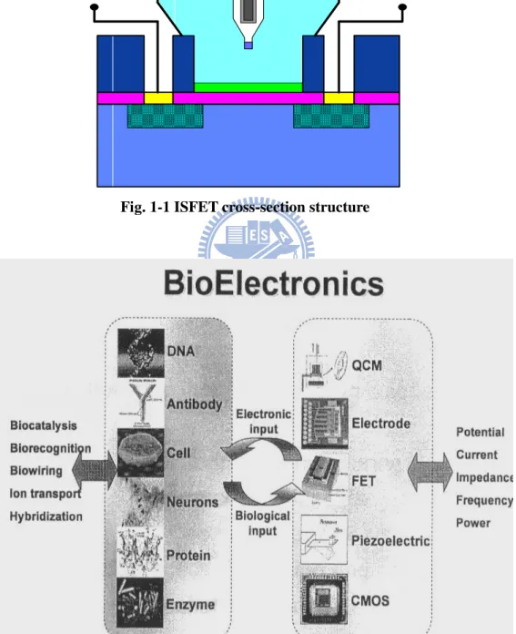
Fig. 1-1
ISFET cross-section structure Fig. 1-2
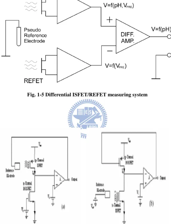
Important platform of Bio-sensors Fig. 1-3
The electrode structures Fig. 1-4
Conventional glass electrode Fig. 1-5
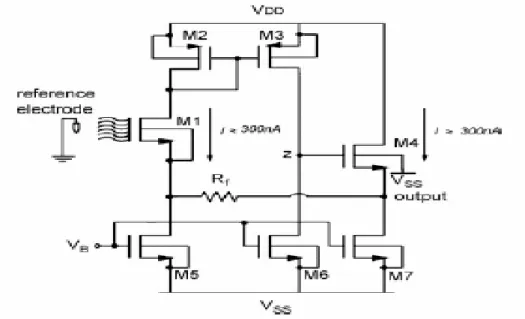
Differential ISFET/REFET measuring system Fig. 1-6
Direct (a) and indirect (b) feedback circuit Fig. 1-7
Sketch of readout circuit with global feedback Fig. 1-8
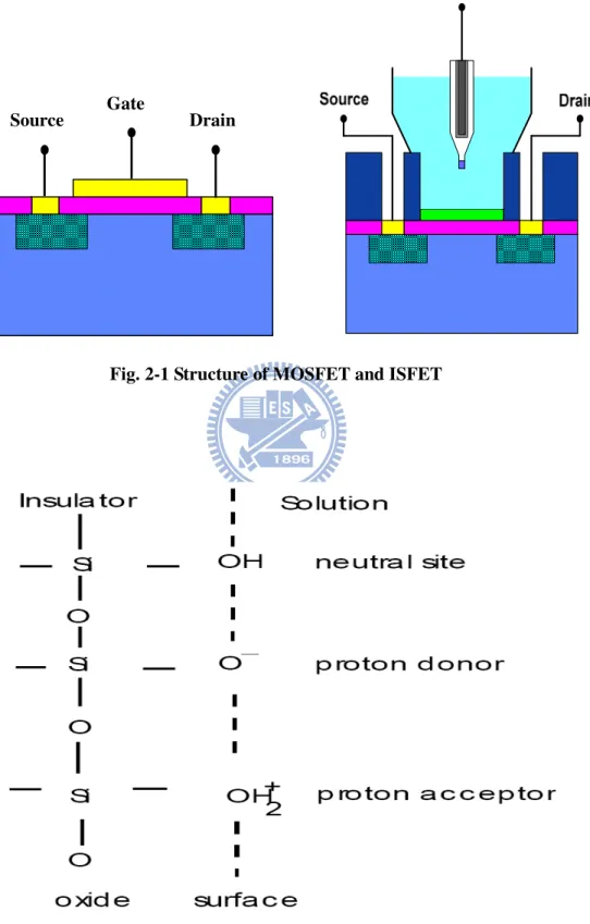
Sketch of an operational amplifier Fig. 2-1
Structure of MOSFET and ISFET Fig. 2-2
Site-binding model Fig. 2-3
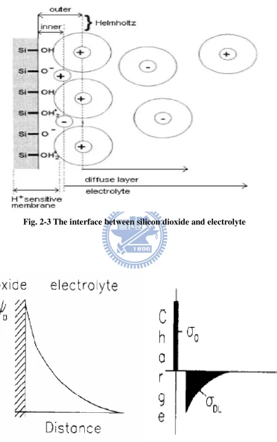
The interface between silicon dioxide and electrolyte Fig. 2-4
Potential profile and charge distribution at an oxide electrolyte solution interface
Fig. 2-5
Schemat Gouy-Chapman-Stern model Fig. 2-6
Series combination of the (a) initial (b) hydrated insulator capacitance Fig. 3-1
Fig 3-2
Chemical formula and sketch for Nafion Fig. 3.3
Measurement set-up Fig. 3-4
Detection principle of pH Fig. 3-5
Detection principle of drift Fig. 4-1
Id-Vg curve of ZrO2 for p-type ISFET before drift
Fig. 4-2
Id-Vg curve of ZrO2 for n-type ISFET before drift
Fig. 4-3
Time to drift in pH 3 buffer solution of p-type ISFEET for 400 minutes
Fig. 4-4
Time to drift in pH 5 buffer solution of p-type ISFEET for 400 minutes
Fig. 4-5
Time to drift in pH 7 buffer solution of p-type ISFEET for 400 minutes
Fig. 4-6
Time to drift in pH 9 buffer solution of p-type ISFEET for 400 minutes
Fig. 4-7
Time to drift in pH 11 buffer solution of p-type ISFEET for 400 minutes
Fig. 4-8
Time to drift in pH 3 buffer solution of n-type ISFEET for 400 minutes
Fig. 4-9
Time to drift in pH 5 buffer solution of n-type ISFEET for 400 minutes
Fig. 4-10
Time to drift in pH 7 buffer solution of n-type ISFEET for 400 minutes
Fig. 4-11 Time to drift in pH 9 buffer solution of n-type ISFEET for 400 minutes
Fig. 4-12
Time to drift in pH 11 buffer solution of n-type ISFEET for 400 minutes
Fig. 4-13
Time to drift rate of p-type ISFET in various buffer solution Fig. 4-14
Time to drift rate of n-type ISFET in various buffer solution Fig. 4-15
Comparison of drift amount between p-type and n-type ISFET in various buffer solutions
Fig. 4-16
Comparison of drift rate between p-type and n-type ISFET in various buffer solutions
Fig. 4-17
Selectivity of the HMDS/ZrO2 structure
Fig. 4-18
Comparison of gm between ZrO2 and the HMDS/ZrO2 structure
Fig. 4-19
Comparison of gm between ZrO2 and the test structures
Fig. 4-20
Selectivity of the PR/HMDS/ZrO2 structure
Fig. 4-21
Time to drift in pH 7 buffer solution of the PR/HMDS/ZrO2 structure
for 400 minutes Fig. 4-22
Sensitivity of the mixture (Nafion1:polyimide1)/HMDS/ZrO2
structure Fig. 4-23
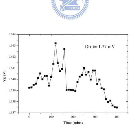
Time to drift in pH 7 buffer solution of the mixture
(Nafion1:polyimide1)/HMDS/ZrO2 structure for 400 minutes
Fig. 4-24
Sensitivity of the mixture (Nafion1:polyimide3)/HMDS/ZrO2
Fig. 4-25
Time to drift in pH 7 buffer solution of the mixture
(Nafion1:polyimide3)/HMDS/ZrO2 structure for 400 minutes
Fig. 4-26
Sensitivity of the polyimide/HMDS/ZrO2 structure
Fig. 4-27
Time to drift in pH 7 buffer solution of the polyimide/HMDS/ZrO2
structure for 400 minutes Fig. 4-28
Table Captions
Table 1-1 Sensitivities and test range for different sensing membranes Table 3-1 Specifications of wafers
Table 3-2 Parameters of sensing layers deposition with sputter
Table 3-3 The test structures of REFET, NF=Nafion, and PI=polyimide Table 4-1 Sensitivity at the optimum operation current
Table 4-2 Comparison between original and modified S/N ratio Table 4-3 Parameters of the test structures; NF=Nafion, PI=polyimide Table 4-4 Parameters of the test structures; NF=Nafion, PI=polyimide
Chapter 1
Introduction
1.1 The reason to use ion-sensing-field-effect-transistor (ISFET)
Ion-sensing-field-effect-transistor (ISFET
)
was developed by P. Bergveld in the 1970s [1]. The important concept of the ISFET (shown in Fig. 1-1) was evolved from the metal-oxide-field-effect-transistor (MOSFET). We can use different sensing films to replace the gate electrode structure of MOSFET. From the electrochemical reaction between the sensing layer and the liquid electrolyte, the pH value can be detected. The parameter, pH value, plays an important role in many fields such as agricultural, chemistry, food chemistry, pharmaceutical industry and human health [2]. For example, the body fluid of living organisms usually has specific pH range. If the pH of the human blood changes by a little as 0.03pH units or less the functioning of the body will be greatly impaired [3].In the early periods, an unstable reference voltage existed for the solution of measure, so the researchers added a stable reference electrode in succession to waiting for the solution of measure in the later researches. Furthermore, the choice of sensing layer is also an emphasis on the researches in the ISFET field because the SiO2 is not
an ideal film. To find a high sensitive and an obvious selective sensing layer is our objective. So the properties of (Table 1-1) ZrO2 [4], Si3N4 [5], Al2O3 [6], Ta2O5 [7] and
SnO2 [8] sensing layer are investigated in the latter researches. With the studies to the
sensing layers, we find some of them can detect specific ions such as K, Na, Ca ions. The ability to recognize the different ions is called as “Selectivity”. Because of the characteristic, ISFET can be used as a biosensor (shown in Fig. 1-2). Besides the
above discussions, it also owns some features. For instance, it can achieve the goal of the small size, strong robustness and rapid response. It is also compatible with the CMOS standard process nowadays. So it can have the lower cost.
1.2 Two kinds of electrodes
The instability is a serious drawback to ISFET. It would detect the incorrect pH value because of the non-ideal issue. From the researches of ISFET, it can utilize the electrodes to stabilize the electric potential in the liquid electrolyte. The most useful electrodes are glass electrode and solid-state electrode shown as Fig. 1-3.
1.2.1 The glass electrode
The first glass electrode is invented by Cremer in 1906. Thereafter, the published researchers focus on the improvement in its application. The major element of the glass electrode is a bulk of glass membrane providing the pass channels for hydrogen ions. Inside the glass membrane is a fixed concentration of HCl or a buffered chloride solution contact with an internal Ag/AgCl reference electrode. We can see the diagram in Fig. 1-4.
The immersion in the chemical buffer solution of the glass electrode can produce the way to transfer ions in the surface of the glass bulk. The transfer reaction for hydrogen ions is the result to the hydration of the surface of the glass membrane. It can not only build up hydrogen ions layer but also stabilize the electric potential [9]. For the reason of the stable voltage, the various components such as Na2O-CaO-SiO2,
Li2O-BaO-SiO2, Li2O-Cs2O-La2O3-SiO2, are doped to the glass material [10]. For
the stable Si-O bond and lead to the change between Li+ and H+: ( _ ) ( )
SiO Li− + glass membrane +H+ solution ( _ ) ( )
SiO H hydrated layer Li solution+
→ − + +
Li+ produce charges and these charges consequently build up the surface potential. From the Nernst equation, we can know that activity of hydrogen ions is related with the surface potential and can easily calculate the potential difference between the outside and inside glasses. The Nernst equation is listed as the following equation. E Eo RTln H
nF α +
= + where E = electrode potential, E0 = standard potential of the electrode, R = gas
constant (8.31441JK-1mol-1), T = temperature (in Kelvin), n = valance (n=1 for hydrogen ions), F = Faraday constant and
H
α += activity of hydrogen ions.
According to the equation, providing that at one side of the interface the activity of the ion of interest is kept constant, the electrode potential is a direct logarithmic function of the ion activity on the other side [10]. And then we can easily define a stable potential suggesting that no interference reaction will occur. The most attractive advantage is established. Because of the advanced IC fabrication techniques, the ISFET-based pH sensor has a big potential for widely application and becomes a new choice for pH detection.
1.2.2 The solid-state reference electrode
As the extensive applications of ISFET, the inconvenience of its large size is also discussed. So we can use the solid-state reference electrode to replace the past glass electrode. The solid-state reference electrode is composed of noble metal such as Ag, Pt, et al. The noble materials are often steady and difficult to react in the aqueous
solutions. But it is unable to produce the same ion-exchange reactions like glass electrode. There is no stable electric potential in the solid-state reference electrode because of the unstable ion-absorbing reaction causing in the metal surface. Some methods are published to solve this problem [11] (Shown in Fig. 1-5). The specific manner is utilizing two ISFET, one of them is high sensitivity and the other one with low sensitivity is called as REFET (Reference Field Effect Transistor). REFET is identical with ISFET except that REFET does not react on the ion concentration to be measured, i.e. REFET is insensitive to the test ion concentration [11]. Even in the identical conditions, ISFET and REFET produce two different voltages. This circuit topology and the use of differential operation amplifier can eliminate the common influences created from the solid-state reference electrodes of ISFET and REFET. The origin of the instability may be the redox reaction or other reactions at noble metal reference electrode and the liquid interface, i.e. the liquid/solid interface. So elimination or reduction of the unstable measured voltage is the focus of investigating the solid-state reference electrode.
1.3 The applications of ISFET: The readout circuit
We could miniaturize the size of ISFET by introducing solid-state electrode. ISFET with solid-state is able to detect the existence and concentration of different ions by itself, but there is an issue of the degree of the accuracy in this case. Generally, a slight degree of the measurement deviation can be adopted. But in some situations of the strict requisitions, such as a health examination or a quarantine of the agricultural products, the measurement accuracy is indispensably necessary. There are two important essentials in the biomedical sensors including the accurate output signal and the stable biasing current and voltage. So the specific circuits are
continuously investigated [11]. Furthermore, the functions of the novel readout circuits are getting more and more as the development of fabrication and the circuit topologies. Nowadays, we can achieve a lot of goals including the low power consumption, reduction the amount of drift and the linearity of the output signal, in only single readout circuit. We can see these circuit sketches in Fig. 1-6 [12] and Fig. 1-7 [13].
Today, we want to produce a wonderful pH sensor with small size and the ability of continuous monitoring. Therefore, the investigations on the part of the readout circuit are getting more and more significant. Low power consumption, the accuracy of measurement results, elimination of influences in the surrounding, the small layout area of the readout circuit, and simplification of design are all our targets. To achieve and combine these benefits in single readout circuit is an important fundamental for the glorious pH sensors.
1.4 Motivation of this work and thesis
Readout circuit could miniaturize the pH-ISFET measurement and provide the accurate output signal. As mentioned before, the unstable issue of the measurement still exists until now. There are many methods to solve the problem. At first, we try to improve the performances of the ISFET. But the result is unapparent. So the researchers focus on the readout circuits. According to Ref. [14], it is an achievable method to reduce the instability obviously. Besides the stability, we can obtain the other advantages at the same time in the present days.
In the readout circuits, we can see the various parts of ISFET-REFET pair, ISFET-MOSFET pair or the arbitrary combinations with the three different devices, no matter the functions of the circuit are identical or different. Besides the pairs,
operation amplifiers are usually used. A normal operation amplifier is shown as Fig. 1-8 [14].
The study is interested in the characteristics of the fundamentals in the readout circuits including ZrO2 gate ISFETs and polymer based REFETs. From the measured
data, we are able to improve the original circuit with the introduction of some specific compensation circuits. We could also use the property of the two devices, the circuit topology, and the feedback concept to stabilize the output voltage and to obtain the better performances from the novel readout circuits in the future.
In chapter 2, the basic theories and non-ideal phenomenon of ISFET are introduced. And the detail process flow of this experiment will be listed in chapter 3. In chapter 4, we will have some discussions about our experimental results and in chapter 5, the future work of this experiment is presented.
1.5 References
[1] P. Bergvled,”Development of an ion-sensitive solid-state device for neurophysiological
measurement”, IEEE Trans. On Bio-Med. Eng. (1970) 70-71
[2] H. Kaden, H. Jahn, M. Berthold, ”Study of the glass/polypyrrole interface in an all-solid-state pH sensors”, Solid State Ionics, vol. 169, pp. 129-133, 2004.
[3] Y. Q. Miao, J. R. Chen and K. M. Fang, “New technology for the detection of pH”,
J. Biochem. Biophys. Methods, vol. 63, pp. 1-9, 2005.
[4] K. M. Chang, K. Y. Chao, T. W. Chou, and C. T. Chang, ”Characteristics of Zirconium Oxide Gate Ion-sensitive Field-Effect Transistors”, Japanese Journal
of Applied Physics Vol. 46 No. 7A pp. 4334-4338 2007.
[5] H. K. Liao, J. C. Chou, W. Y. Chung, T. P., and S. K. Hsiung, ”Study on the interface trap density of the Si3N4/SiO2 gate ISFET”, Proceeding of the Third East
Asian Conference on chemical Sensor, Seoul, South Korea, pp. 394-400, Nov
1997.
[6] S. Jamasb, S. D. Collins, R. L. Smith, ”A Physically-based Model for Drift in Al2O3-gate pH ISFETs ” in International Conference on Solid-State Sensors and Actuators Chicago, June, 1997.
[7] P. Gimmel, B. Gompf, D. Schmeiosser, H. D. Weimhofer, W. Gopel, and M. Klein, “Ta2O5 gate of pH sensitive device comparative spectroscopic and electrical
studies”, Sensors and Actuators B vol. 17 pp. 195-202, 1989.
[8] Y. Q. Miao, J. R. Chen and K. M. Fang, “New technology for the detection of pH”,
J. Biochem. Biophys. Methods, vol. 63, pp. 1-9, 2005.
[9] 董勝敏, 王承遇, 潘玉昆, ”pH 玻璃電極的現狀與發展”, GLASS & ENAMEL, vol. 32, No. 2, pp. 54-57, Feb. 2004.
[10] P. Bergveld, “ISFET, Theory and Practice”, in IEEE Sensor Conference, Toronto, Oct. 2003.
[11] P. Bergveld, “Thirty years of ISFETOLOGY What happened in the past 30 years and what happen in the next 30 years”, Sensors and Actuators B, vol. 88, pp. 1-20, 2003.
[12] U. Dinnar, Claudio G. Jackobson, ”CMOS Readout Circuit for Biomedical ISFET-Based Microsystems”, The 16th Europaen Conference on Solid-State Transducers, Prague, Czech Republic, Sepetember 15-18, 2002.
[13]
B. Premanode, N. Silawan, W. P. Chan
c,and C. Toumazou
a, “A composite ISFET readout circuit employing current feedback”, Sensors and Actuators B, vol. 127, pp. 486-490, 2007.[14] Yang Zhen, Yan Yong-hong, and Qi Liang-jie, ”A Integrated pH-ISFET Sensor With CMOS Technology”, Semiconductor Technology, vol. 29, No. 12, pp. 56-59, Dec. 2004.
Chapter 2
Theory Description
2.1 The basic concepts and applications of pH
The two letters, “pH”, is an abbreviation of the potential of Hydrogen. About 100 years ago, 1909, the concept of pH was published by Danish chemist S. P. L. Sørensen [1]. pH is an important parameter for determining the acidity or alkalinity of different unknown chemical solutions. Solutions are considered acidic with a pH less than seven, while those with pH greater than 7 are considered alkaline. pH 7, the standard between the acid and alkaline solutions, is defined as neutral because of the equality of the concentration of H3O+ and the concentration of OH- at 25℃ in the pure water at
the specific pH value [2]. pH also plays an important role in several kinds of domains such as agricultural, chemistry, food chemistry, pharmaceutic industry and human health [3].
We can use the following formula to find out the pH value we needed. The formula used to calculate pH value is defined as:
pH log10α[H ] +
= −
(2-1) where
α
is the activity coefficient and [H+] is the molar concentration of solvated protons in units of moles per liter (moles/L). From equation (2-1), we can know that pH value related to the amount of available hydrogen ions not the concentration of hydrogen ions.2.2 Operating theory of ISFET
Ion-selective field effect transistors (ISFETs) were first published by P. Bergveld in the 1970s. Besides the structure of the gate, the other parts of ISFETT are similar to MOSFET (Metal Oxide Semiconductor Field Effect Transistor). The gate electrode of ISFET is substituted for a reference electrode and immersed in an undefined solution contacted with the gate sensing layer. The first purple of using a reference electrode is that a capacitor (with the gate oxide as the dielectric material) needs two parallel plates for connecting. The two parallel are respectively the silicon substrate and the electrolyte [4]. The second reason of the existence of the reference electrode is stable while ion transferring. Without the reference electrode, the electrolyte potential is getting more unstable and easily disarranged by the disturbances from the surrounding. We can know the main function of ISFET is measuring the concentration of various kinds of ions in different chemical liquid solutions from the above-mentioned reasons. A schematic structure of MOSFET and ISFET are shown in Fig. 2-1.
2.2.1 The evolution from MOSFET to ISFET
The concept of ISFET comes from MOSFET. So the fundamental framework, geometric structure, and the theories of operating, are almost similar. We usually bias ISFET in the linear region. So we can get the expression of ISFET from the same biasing condition of MOSFET. For both MOSFET and ISFET, the drain current in the triode region is:
D OX
(
VGS Vt)
VDS VDS L W C I − − = 2 1 µ (2-2) where Cox is the oxide surface capacitor in the unit of F/Cm2, and µ is the mobilityof the majority carriers in the channel region. W and L are the denotations of the width and length of the channel respectively. An useful parameter, β, defined as
ox W C L β =µ ,
plays an important role in the field of designing electrical circuits. From the advanced process steps and ideal circuit design, we can make the threshold voltage Vt and the drain-source voltage VDS almost const. Thus the drain current ID is
direct proportion to the VGS in MOSFET.
The Vt term in equation (2-2) can be calculated as shown in equation (2-3).
F OX B SS OX Si M t φ C Q Q Q q V =φ −φ − + + +2 (2-3) where φM is the work-function of the metal gate, φSi is the work-function of silicon,
ox
Q is the accumulated charge in the oxide, Qss is the surface charge density between oxide and silicon surface, QB is the depletion charge in the silicon and φf is
Fermi-potential [5].
In the case of ISFET, the metal gate is taken off [2]. The expression of threshold voltage is needed to modify. The interface between the solution and the gate oxide and the interface between solution and the reference is considered [6]. It is shown as below: F OX B SS OX Si sol ref t φ C Q Q Q q Ψ χ E V = + − 0−Φ − + + +2 (2-4) The term is the reference electrode potential related to vacuum level Eref, which includes φM
, χ
sol
is the surface dipole potential of the solution, which is a constant. All terms are constant except Ψ0, it is the kernel of ISFET sensitivity to the electrolyte
pH value which is controlling the dissociation of the oxide surface. The way to gain a pH sensitive ISFET is to concentrate on the surface between oxide and solution. The detailed investigations in the oxide-electrolyte interface are able to help us to find out the best oxide instead of a priori silicon dioxide as used for MOSFETs [6].
There is a chemical reaction in the part of oxide-electrolyte interface [4][6][7]. The sketches of the reaction are illustrated as Fig. 2-2, Fig. 2-3, and Fig. 2-4. We can explain the reason of the phenomenon as the SiO2 sensing layer. The silicon hydroxyl
groups contained in the surface of the oxide sensing layer can donate or accept a proton from the electrolyte. The chemical reaction will build up charges and develop the electrical potential in the region. The phenomenon can be explained with the site-binding model introduced from by Yate et al [8]. The statement can describe the interface with the combination and generation of protons from the silicon hydroxyl groups. The neutral sites may become negatively charged or positively charged surface groups respectively by donating or accepting protons. The surface reactions are: SiOH← →Ka SiO−+HS+ (2-5) H ++SiOH←→ SiOH2+ b K S (2-6)
where HS+ represents the protons in the at the surface of the oxide, Ka and Kb are the
chemical equilibrium constants. Eq. (2-5) and Eq. (2-6) imply the surface chemical reaction dynamically equilibrated, too.
The proton concentration distribution is affected by the potential between the oxide sensing layer and the chemical solution, and according to the Boltzmann [9]. The Boltzmann equation is stated as the following equations:
exp S B o H H q a a kT ψ + + − = (2-7) or in the from of pH 0 2.3 S B q pH pH KT = + Ψ (2-8)
where S H a + and S H
a + are the activity of HS +
at the oxide surface and the bulk of the solution respectively, k is the Boltzmann constant, T is the absolute temperature,
o
ψ is the surface potential, pHs is the pH value at the oxide surface, pHB is the pH value in the bulk of the solution, q is the element charge.
2.2.3 The derivation of pH sensitivity of ISFET
To derivate the pH value, we should know the surface density of the amount of the surface site NS and the surface charge density σ0 (C/m
2
). They are shown as below equations. = + − + + 2 SiOH SiO SiOH S v v v N (2-9) =(vSiOH + +vSiO−)=−qB 2 0 σ (2-10)
where vSiOH2+, vSiO- and B is the symbol of the number of positively charged,
negatively charged, neutral groups in mole per unit area respectively [5]. From Ref. [2] [6], the detailed derivation ofσ0 can be found.
2 2 S S S a b H o a b b H H a K K qNs K K K a a σ + + + − = + + (2-11) where Ka and Kb are dissociation constant. We can get the intrinsic buffer capacity
int
β after taking the differential to σ0 with the variable pH. β is also the int function of the activity of surface H+-ions.
o int S S B q q pH pH σ β ∂ ∂ = − = − ∂ ∂ (2-12) We can obtain βint for combining equation (2-11) and (2-12).
(
)
2 2 int 2 2 4 2.3 S S S S S b H a b H a b S H a b b H H K a K K a K K N a K K K a a β + + + + + + + = + + (2-13)In this case, it is capable of buffering small changes in surface pH (pH ) only S
and is not in bulk pH (pHb), so it is called intrinsic. And NS, Ka and Kb are related to
oxide. To hydrolyze the surface will create more surface sites which can make the intrinsic buffer capacity and the sensitivity more [6].
According to the charge neutrality, the surface charge σois balanced by an equal but opposite charge, σdl, in electrolyte. The two opposite charges, σoandσdl, parallel to each other form the electrical double layer structure, and the integral electrical double-layer capacitance is named Cdl i, . The relation between them is
,
dl o Cdl i o
σ = −σ = − ×ψ (2-14) where the potential of the suface to the bulk of solution is ψo =ψs−ψB [6]. The figure of the Gouy-Chapman-Stern model is shown as Fig. 2-5. We can calculate the integral double-layer capacitance Cdl i, with the Gouy-Chapman-Stern model [10]. The Gouy-Chapman-Stern model involves a diffuse layer of charge in the solution and starts at a distance of xE from the surface. A series network of the Helmholtz-layer
capacitance (the Stern capacitance) and a diffusion layer capacitance is composed of the double-layer capacitance. And the charge in the diffusion layer, σdl, is calculated as: − = kT zq n kT E r dl 2 sinh 8 ε ε0 0 φ σ (2-15) where φE is the potential at xE, n0 is the total concentration of each ion in the bulk
solution, z is the valence number of the ions., and the parameters εr, ε0, k, q and T are their normal meanings.
According the Kirchhoff's Voltage Law, we know the voltage drop across the Stren capacitance equaled with the difference between the potential ψ1 at YT and the
0 0 1 0 0 0 E Stren r x C σ σ ψ ψ ψ ε ε = − = − (2-16) So we can express the integral double-layer capacitance with the variables ψ0 and the electrolyte concentration from Eq. (2-13) and Eq. (2-14). The ability of the double layer to store charges, which is defined in response to a small charge in the potential
0 0
σ ψ
∂
∂ , is denoted as Cdif, and calculated:
0 0 0 dl dif C σ σ ψ ψ ∂ ∂ = − = ∂ ∂ (2-17) We can achieve the purpose of simplicity for taking the expression for the inverse Cdif. Eq. (2-18) clearly shows that this capacitance is composed of two
components in series: 0 2 2 0 0 0 1 1 1 1 2 cosh( ) 2 dif Stren r C C z q n zq kT kT ψ σ ε ε ψ ∂ = = + ∂ (2-18) It shows that the effect of a small change in the surface pH (pHs) on the change in the
surface potential ψ0 to combine Eq. (2-12) and Eq. (2-17):
0 0 0 int 0 S S dif q pH pH C ψ ψ σ β σ ∂ ∂ ∂ − = ⋅ = ∂ ∂ ∂ (2-19) Rearrange Eq. (2-19) gives the general expression for pH sensitivity of an ISFET of the electrostatic potential to changes in the bulk [2]:
0 2.3 B kT pH q ψ α ∂ = − ⋅ ∂ (2-20) where 2 int 1 2.3 1 diff kTC q α β = + (2-21)
The dimensionless sensitivity parameter α, which varies between 0 and 1, is associated with the intrinsic buffer capacity βint and the double-layer capacitance
Cdif. The parameter α is almost equal unity when βint is extreme large and Cdif
approaches zero. The ISFET has a so-called Nernstian sensitivity of precisely -59.2mV/pH at 298K, which is also the maximum achievable sensitivity. The ordinary
SiO2 film compatible with the standard CMOS fabrication process flow can not fit the
requirements of a high value of βint. In the condition, the pH sensitivity is only about 30mV/pH. So it is impossible to find the high sensitivity sensing films. These materials included high sensitivity have been investigated such as Si3N4 [11][12],
Al2O3 [13][14], Ta2O5 [11][14], HfO2 [14], and SnO2 [15].
2.3 The drift phenomenon of ISFET
The phenomenon called as drift is a change of the threshold voltage of an ISFET. It is difficult to identify the cause of this phenomenon, which could be either a surface or a bulk effect, or both. The trap of hydrogen-bearing species can be considered as the surface effect, and the hydration of the insulator after immersed in pH solution can be categorized as the bulk effect. And the followings are the possible causes of drift [16].
(1) Injection of electrons from the electrolyte at strong anodic polarizations created negative space charge inside sensitive film.
(2) Some surface effects, such as the rehydration of a surface that is partially dehydrated and ion exchange involving OH− ions.
(3) Variation of the surface state density (D ) at the it Si SiO interface which 2
means the drift dependence of diffusion mechanism.
(4) Drift of sodium ion under the influence of the insulator field. Given an effective diffusion coefficient D , it is clear that a bulk redistribution of eff
sodium which has left a trap near the edge of the SiO2.
According to Ref. [16], we can know the two kinds of the drift mechanisms, the surface effect and the bulk effect to the various sensing layers. The concept of the trap of hydrogen-bearing species can be seen as the application of the site-binding model. In 1998, Jamasb proposed a physical model quantitatively to explain drift in terms of the bulk effect, hydration of the silicon nitride surface [17].
It is known that the drift phenomenon of an ISFET is modeled by implementing a hopping transport mechanism, known as dispersive transport [18] [19], to determine the rate of hydration of the sensing layer. We can see the dispersive transport in a broad class of disordered materials. Dispersive transport leads to a characteristic power-law time decay of diffusivity [20] which can be described as:
1
00 0
( ) ( )
D t =D ωt β− (2-22)
where D00 is a temperature-dependent diffusion coefficient which obeys an Arrhenius relationship,ω0 is the hopping attempt frequency, and β is the dispersion parameter satisfying 0<β < . In turn, dispersive transport also leads to decay in 1 density of sites/traps occupied by the species undergoing transport [20]. This decay is described by the stretched-exponential time dependence given by:
/ ( ) / (0) exp[( / )]
S T S T
N t N t τ
∆ = ∆ − (2-23) where ∆NS T/ ( )t is the area density (unit of cm-2) of sites/traps occupied, τ is the time constant combined with structural relaxation, and β is the dispersion parameter.
2.3.2 Expression for drift
can achieve the purpose easily in the normal condition. But the sensing layer is getting hydrated all the time when the electrode is immersed in the aqueous electrolyte. The hydration makes the chemical composition of the sensing layer different from that of the bulk of the sensing material. Consequently, the dielectric constant is dissimilar to that of the un-hydrated layer. The equivalent insulator capacitance is also determined by the series combination of the surface hydration layer and the underlying sensing film, will exhibit a slow, temporal change. When the ISFET is biased in the region we need, the gate voltage will simultaneously exhibit a change to keep a constant drain current. The change of the gate voltage can be written as [21]:
( ) ( ) (0)
G G G
V t V t V
∆ = − (2-24) Since the voltage drop inside of the semiconductor is kept a constant, ∆V tG( ) becomes:
( ) [ ( ) (0)] [ ( ) (0)]
G FB FB ins ins
V t V t V V t V
∆ = − + − (2-25) where VFB is the flat-band voltage and V is the voltage drop across the insulator. ins
FB
V and V are given by the following expression: ins 0 sol Si OX SS FB ref OX Q Q V E q C χ Φ + = + − Ψ − − (2-26) ( B inv) ins OX Q Q V C − + = (2-27) where the Q is the inversion charge. If the pH, temperature, and the ionic strength inv
of the solution are kept constants, Eref , Φ , Si Ψ , and0 sol
χ can be neglected, so the drift an be rewritten as:
1 1 ( ) ( )[ ] ( ) (0) G OX SS B inv i I V t Q Q Q Q C t C ∆ = − + + + − (2-28) In our study, the gate oxide of the fabricated ISFET was consist of two layers, a lower layer of thermally-grown SiO2 of thickness, tL, and an upper layer of
sputter-grown ZrO of thickness, 2 t . U CI(0) is the effective insulator capacitance given by the series combination of the thermally-grown SiO2 capacitance, εL tL, and the sputter-grown ZrO capacitance, 2 εU tU . C t is analogous to i( ) CI(0), but an additional hydrated of capacitance make Ci always smaller than CI, εHL tHL, at the oxide-electrolyte interface must be considered, and the sputter-grown ZrO 2
capacitance is now given by εU [tU −tHL] . The series combinations of the capacitance are illustrated in Fig. 2-6. Therefore, the drift is given by:
( ) U HL ( ) G OX SS B inv HL U HL V Q Q Q Q ε ε t t ε ε − ∆ = − + + + (2-29) From this equation, we can know that the drift of gate voltage ∆VG if the substrate type was different, it is depend on the Q and inv Q . Other terms at Eq. B
(2-29) can be seen as constant value no matter what the substrate is. According to this assume, it is possible to eliminate the drift or hold the drift to be a constant at any other pH aqueous solution through the CMOS ISFET. By applying dispersive transport theory, an expression for tHL( )t is given by [22]
{
}
( ) ( ) exp ( / ) HL HL t t =t ∞ − − t τ β (2-30) with 1 00 0 / (0) ( ) S T HL D hydr D N t A N β ω β −∆ ∞ = (2-31)where A is the cross-sectional area, and D Nhydr is the average density of the hydrating species per unit volume of hydration layer. Hence, combination of eqns.2-24 to eqns.2-30 the gate voltage drift can be expressed by the following equation:
{
}
( ) ( ) U HL ( ) 1 exp ( / ) G OX SS B inv HL U HL V t Q Q Q Q ε ε t t τ β ε ε − ∆ = − + + + ∞ − − (2-32)According to Eq. (2-32), we can know that if the immersing time of the gate oxide is long enough, the shift of gate voltage will approach almost a constant value which is greatly dependent on the hydration depth, tHL( )∞ .
2.4 References
[1] Y. Q. Miao, J. R. Chen and K. M. Fang, “New technology for the detection of pH”,
J. Biochem. Biophys. Methods, vol. 63, pp. 1-9, 2005.
[2] P. Bergveld, “ISFET, Theory and Practice”, in IEEE Sensor Conference, Toronto, Oct. 2003.
[3] H. Kaden, H. Jahn, M. Berthold, ”Study of the glass/polypyrrole interface in an all-solid-state pH sensors”, Solid State Ionics, vol. 169, pp. 129-133, 2004.
[4] P. Bergveld, “Thirty years of ISFETOLOGY What happened in the past 30 years and what happen in the next 30 years”, Sensors and Actuators B, vol. 88, pp. 1-20, 2003.
[5] H.K. Liao, et al. ”Study on pHpzc and surface potential of tin oxide gate ISFET”, Materials Chemistry and Physics, vol. 59, pp. 6-11, 1999
[6] R.E.G. van Hal et al. , “A general model to describe the electrostatic potential at electrolyte oxide interface”, Advance in Colloid and Interface Science, vol.69, pp. 31-62, 1996.
[7] Miao Yuqing , Guan Jianguo, Chen Jianrong, “Ion sensitive field transducer-based biosensors”, Biotechnology Advances, vol. 21, pp. 527-534, 2003.
[8] D. E. Yates, S. Levine, and T. W. Healy, “Site-binding model of the electrical double layer at oxide/water interface”, J. chem. Soc. Faraday Trans. I, vol. 70, pp. 1807-1818, 1974.
Physical and Theoretical Aspects”, IEEE Transactions on Electron Device, vol. ED-26, NO. 11, Nov., 1979
[10] 吳浩青, 李永舫, ”電化學動力學”, 科技圖書公司, 2001 年 2 月 [11] Tadayuki Matsuo, Masayoshi Esashi, ”Methods of ISFET Fabrication”, Sensors
and Actuators, vol. 1, pp. 77-96, 1981.
[12] Imants R. Lauks, Jay N. Zemel, “The Si3N4/Si Ion-Sensitive Semiconductor Electrode ”, IEEE Transactions on Electron Devices, vol. ED-26, no.12, pp. 1959- 1964, Dec., 1979.
[13] J. C. Chou, C. Y. Weng, “Sensitivity and hysteresis effect in AL2O3 gate pH- ISFET”, Materials Chemistry and Physics, vol. 71, pp. 120-124, 2001.
[14] P.D. van der Wal et al. ,”High-K Dielectrics for Use as ISFET Gate Oxide”, in
Sensors, Proceedings of IEEE.2004
[15] H. K. Liao et al., ”Study of amorphous tin oxide thin films for ISFET applications”, Sensors and Actuators B, vol.50, pp. 104-109, 1998.
[16] Luc Bousse, Piet Bergveld, “The Role Of Buried OH Sites In The Response Mechanism Of Inorganic-Gate pH-Sensitive ISFETs”, Sensors and Actuators, vol. 6, pp. 65-78, 1984.
[17] S. Jamasb, S. D. Collins, and R. L. Smith, ”A Physical Model for Threshold Voltage Instability in Si3N4-Gate H+-Sensitive FET’S (pH ISFET’s)”, IEEE Transactions on Electron Devices, vol. 45, no. 6, pp. 1239-1245, Jun, 1998.
[18] G. Pfister, H. Scher, ”Time-dependent electrical transport in amorphous solid: As2Se3”, Physical Review B, vol. 15, no. 4, pp. 2062-2082, Feb., 1977.
[19] H. Scher, Elliott W. Montroll, ”Anomalous transit-time dispersion in amorphous solid”, Physical Review B, vol. 12, no.6, pp. 2455-2477, Sep., 1975.
Arising from Dispersive Diffusion of Hydrogen in Amorphous Sillicon”,
Physical Review Letters, vol. 59, no.9, pp. 1037-1040, Aug. 1987.
[21] S. Jamasb, S. D. Collins, R. L. Smith, ”A Physically-based Model for Drift in Al2O3-gate pH ISFETs ” in International Conference on Solid-State Sensors and Actuators Chicago, June, 1997.
[22] S. Jamasb, S. D. Collins, R. L. Smith, ”A physical model for drift in pH ISFET ”, Sensors and Actuators B, vol. 49, pp. 146-155, 1998.
Chapter 3
Experiment and Measurement
3.1 Introduction
The structure of ISFET is similar to the conventional MOSET. The most difference between MOSFET and ISFET is the gate electrode. The ISFET takes the gate membrane as a sensing layer immersed in the pH-solution [1]. In the experiment, we produce the n-type ISFET and the p-type ISFET. From the derivations of the ISFET sensitivity in chapter 2, there are no factors about electrons and holes. So we can guess that the sensitivity must be the same whether the substrate is n-type or p-type.
Besides the ISFET, we also produce the REFET. REFET is identical with ISFET except that REFET does not react on the ion concentration to be measured, i.e. REFET is insensitive to the test ion concentration [2]. We use the polymer materials coated on the ZrO2 sensing layer to get the insensitive REFET. And then, we measure
the electric parameters including the drift amount and the sensitivity of ISFET and REFET respectively.
3.2 The fabrication process flow of ISFET and REFET
The all procedures of experiment are accomplished in NDL (National Nano Device Laboratory) and NFC (Nano Facility Center). The fabrication process flow is shown in Fig. 3-1. And the detailed steps are listed in this section.
1. RCA clean.
2. Wet oxide growth 6000Ǻ, 1050°C, 65mins. Part 2:
3. Mask#1 for the definition of the regions of Source/Drain. 4. Wet etching of unblocked silicon dioxide.
5. Dry (Screening) oxide growth 300 Ǻ, 1050°C, 12mins. 6. Source/Drain implantation:
Dose= 5*1015 (1/cm2), Energy= 15Kev (Boron) for p-type ISFET. Dose= 5*1015 (1/cm2), Energy= 25Kev (Phosphorus) for n-type ISFET. The Above detailed information is in Table 3-1.
7. Source/Drain annealing, 950°C, 60mins. Part 3:
8. PECVD Oxide deposition 1µm. Part 4:
9. Mask#2 for the definition of the contact hole and gate region. 10. Wet etching of unblocked silicon dioxide.
11. Dry oxide growth 100 Ǻ, 850°C, 60mins. Part 5:
12. Mask#3 for the definition of the sensing layer region. 13. Sensing layer (ZrO2) deposition by Sputtering 300 Ǻ.
14. ZrO2 sintering 600°C, 30mins.
Part 6:
15. Mak#4 to define the contact region. 16. Al deposition by sputtering 5000 Ǻ. Part 7:
18. Al sintering 400°C, 30mins Part 8:
19. Coating the polymer-based material as the REFET sensing layer.
3.3 The illustration of the core parts
In part 1, RCA clean is for the elimination of ions and clean for the silicon surface, to make the growing equality of Wet Oxide better.
In part 2, the area of the defined Source/Drain grow a layer of 100A screen oxide to protect the surface when ion-implantation. The other use of this layer of oxide is avoid the channeling effect while implantation. After ion-implantation, the doped ions with high energy destroy the structure of lattice sites of the silicon substrate, and repair it by the way of anneal.
In part 3, then using PECVD grow oxide 1 mµ as insulation to prevent buffer solution effect the device when ISFET is immersed in the electrolyte.
In part 4, decide the gate oxide region, and then use BOE etching the unblocked oxide. It grows the better quality gate oxide100A with dry oxide.
In part 5, define the sensing layer region for growing 300A ZrO2 cause its
property of the high sensitivity, which is about 57mv/pH [3]. Table 3-2 is the sputtering parameters.
In part 6, deposition of 5000A Al for the defined electrode region.
In part 7, finished Backside Al evaporation 5000A is the primary process of ISFET.
In part 8, coating the polymer materials cause of its insensitivity onto the ISFET sensing layer.
adhesion of the interface between the ZrO2 sensing layer and the insensitive polymer
material.
In step 19, an important step in the process of REFET fabrication, we coat the polymer-based material onto the HMDS layer as the REFET sensing element. We use a three-layer structure to form the REFET sensing region. The HMDS and the specific polymer-based material are coated from bottom to top onto the ZrO2 sensing layer.
These materials conclude epoxy, the mix composition of phtoresistance (PR) and Nafion (NF), and the different ratio of the mixture of Nafion and polyimide (PI). The experiment test structures are listed in Table 3-3.
According to the data, Nafion (shown as Fig.3-2) is extremely resistant to chemical attack and able to be used in relatively high temperature, so Nafion can protect for the underlying layers from damaging. There is also an additional advantage for using Nafion. It is that Nafion is a cation exchange polymer, i.e. NFafion will not affect the hydrogen ions to pass and any sensitivity decreased. The coating procedure has to be controlled carefully, following is our process flow:
1. Prepare Epoxy, the mixture of NF and PR (FH6400) with the ratio of NF/PR = 1/1, the mixture of NF and PI with the ratio of NF/PI = 1/1 and 1/3, and the pure PI.
2. Dropping the above materials onto the HMDS above the ZrO2 sensing
layers. Dried in air for 30 hours, these materials become colloid with thickness of 5-10um.
3.4 Measurement system
We obtain the I-V curves of the pH-ISFET from the measurement using HP4156 as measurement tool and the system (shown in Fig 3-3) to investigate the characteristics of the regular ISFETs and the REFET structures with the different polymer-based sensing layers. To reduce the disturbance from the environment, such as light influence, the entire measurement procedures were executed in a dark box [4]. The measured pH values are 1, 3, 5, 7, 9, 11, 13, and the pH buffer solution were supplied by the Riedel-deHaen corp.
3.4.2 The measurement of pH sensitivity
A HP-4156 semiconductor parameter analyzer system were set up to measure the
I-V characteristic curves, in which include IDS-VGS and IDS-VDS curves at some specific
controlled temperature. We must be careful while dropping the pH-buffer solution at the sensing region. Because of the small sensing areas, it could easily generate the air bubbles in the interface. Consequently, in order to measure in the more stable situation, we began to measure after about 30 seconds while the sensing layer getting immersed in the pH buffer solutions.
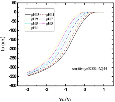
From IDS-VGS curves, we can extract the pH sensitivity (in the unit of mV/pH) of
ZrO2 pH-ISFET. First, we should decide the specific bias IDS usually at the point of
the maximum transconductance, i.e. the maximum slope of IDS-VGS curve. The
sensitivity of pH-ISFET, the gate voltage difference between different pH value buffer solutions at the constraint of the chosen current IDS in the IDS-VGS curve, is obtained.
The illustration to find the selectivity is the sketched in Fig. 3-4.
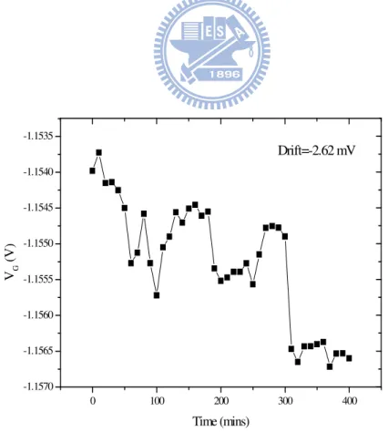
3.4.3 The measurement of drift
To obtain the more accurate drift amount, we put the n-type and the p-type ISFETs respectively immersed in the buffer solution with pH 3, 5, 7, 9, 11 in the periods of 12 hours before measuring. Similarly, we put the REFETs into the pH 7 buffer solution in the period of 90 minutes before measuring. The REFET breaks easily so that we take the less immersion time. As the similar manner in measuring the selectivity, we can sketch the gate voltage versus time in 400 minutes with the equal intervals of 10 minutes. The illustration to find the drift is the sketched in Fig. 3-5.
3.5 References
[1] P. Bergvled,”Development of an ion-sensitive solid-state device for neurophysiological
measurement”, IEEE Trans. On Bio-Med. Eng. (1970) 70-71
[2] P. Bergveld, “Thirty years of ISFETOLOGY What happened in the past 30 years and what happen in the next 30 years”, Sensors and Actuators B, vol. 88, pp. 1-20, 2003.
[3] K. M. Chang, K. Y. Chao, T. W. Chou, and C. T. Chang, ”Characteristics of Zirconium Oxide Gate Ion-sensitive Field-Effect Transistors” Japanese Journal of
Applied Physics Vol. 46 No. 7A pp. 4334-4338 2007.
[4] Paik-Kyun Shin, ”The pH-sensing and light-induced drift properties of titanium dioxide thin films deposited by MOCVD”, Applied Surface Science, vol. 214, pp. 214-221, 2003
Chapter 4
Results and Discussions
4.1 Introduction
The drift is an unavoidable phenomenon of pH-ISFETs, some studies already indicate that the gate voltage shift according to the immersed time goes on. It makes the inaccuracy of the output signal and the lower reliability. We will discuss the experiment results and propose a method to reduce the influence. In addition to drift, we also list the selectivity of p-type and n-type ISFET.
In section 4-2, the important properties of REFET such as the drift and the sensitivity are investigated. From the properties, we can choose the suitable inactive material as the REFET sensing layer.
4.2 The p-type and n-type ISFET
We choose ZrO2 as a sensing film of pH-ISFET for the reason of the higher
sensitivity. Fig. 4-1 and Fig. 4-2 individually represent the measured IDS-VGS curves
from pH 1 to pH 13 of the p-type and the n-type pH-ISFETs. The sensitivity is 57.8 mV/pH for the p-type ISFET and 58.73 mV/ pH for the n-type ISFET. The bias conditions of the two ISFETs are all arranged in Table 4-1. The high sensitive ZrO2
gate ISFET in the readout circuits could accomplish the high revolution while determining the pH value. Besides of the higher sensitivity, the ZrO2 film also
includes other advantages [1].
ZrO2 pH-ISFET. According to Ref. 2, we know the drift phenomenon is a complex
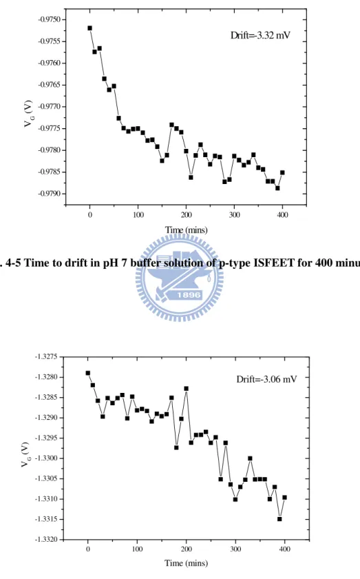
function with the variables such as containing time, sensing film quality and pH aqueous solution. In order to obtain the more precise experiment results, the time and the film must be controlled at same condition in the different pH aqueous solutions. Fig. 4-3 ~ 4-7 are the gate voltage with times for 400 minutes drift in the intervals of equal 10 minutes to the pH 3, 5, 7, 9, 11 aqueous solution of p-type ISFET. Similarly, Fig. 4-8 ~ 4-12 show times for 400 hours drift in the pH 3, 5, 7, 9, 11 aqueous solution of n-type ISFET. From these results, we can find that the drift is a time dependent function which is obeyed with the study investigated by S. Jamasb [3]. The model presented by hydration S. Jamasb indicates that the hydration is a continuous process. The immersion in the solutions only diminishes the drift amount. The action can not vanish the phenomenon.
We also find that the drift phenomenon is related with the pH aqueous solution from Fig. 4-13 and Fig. 4-14. The drift comparison between p-type ISFET and n-type ISFET are listed in Fig. 4-15 and Fig. 4-16. The drift rate increasing with pH value is obeyed with prior research [4]. From our measurements, the direct proportion between the drift rate and the pH value almost exists no matter the categories of ISFET. The possible mechanism of the result is discussed in the following. OH- plays a major role in the hydration action. In the alkali solutions, the more hydroxyl ions make the hydration more. So the drift rates increase with pH value.
From the experiment results, a possible method is proposed to reduce the drift influence at the region of pH 5 – pH 11. In the n-type ISFET, we define the real gate voltage N = n - ∆n. n represents the gate voltage of the ideal n-type ISFET, and -∆n is the drift amount of the n-type ISFET. We can know that n and ∆n are both positive numbers. So the signal to noise ratio is indicated as S/N|n-type ISFET = n/∆n. In the
positive numbers. To reduce the drift effect, we can define a new variable T = N – P. From the above discussions, we can find T = (n+p) – (∆n-∆p). And then the S/N ratio is calculated as S/N|T = n + p/∆n - ∆p. By comparing the three S/N ratios, we know
that S/N|T is larger than S/N|n-type ISFET and S/N|p-type ISFET. The comparison between the
original S/N and the modified S/N is listed in Table 4-2. From Table.4-2, the proposed method can enhance the S/N ratio. In other words, we can reduce the drift influence with the introduction of the new variable T.
4.3 The results in the REFET structure
We coat the HMDS film to improve the adhesion between the ZrO2 layer and the
selected materials. Because of the focus is other materials in this experiment, we do not hope the additional function provided from HMDS. Fig. 4-17 is the selectivity of the structure of HMDS/ZrO2. It shows that HMDS is not the major factor in the
reduction of the sensitivity. The transconductance comparison between the ZrO2 layer
and the HMDS/ZrO2 structure is shown in Fig. 4-18. The transconductances are
almost the same. From Fig. 4-17 and Fig. 4-18, HMDS is an acceptable choice for improving the adhesion.
The parameter, transconductance (gm), is an important property for the decision
whether a material was chosen as the REFET sensing layer. It is troublesome to design two different circuits to maintain the reference bias point if the transconductance of the specific material is not similar with that of the ZrO2 gate
ISFET. The second reason for the same transconductance is the essentiality to select the REFET material. REFET is identical with ISFET except the low pH sensitivity. Usually, we take ISFET and REFET to combine together with a differential OP amplifier. The output signal is only associated with the pH value after the elimination