國
立
交
通
大
學
電機資訊學院 資訊學程
碩
士
論
文
使用正規符號模型驗證器的聲明檢驗法
Automatic Assertion Checking Using Formal Symbolic Model Verifier
研 究 生:汪加元
指導教授:周景揚 博士
莊仁輝 博士
使用正規符號模型驗證器的聲明檢驗法
Automatic Assertion Checking Using Formal Symbolic Model Verifier
研 究 生:汪加元 Student:Chia-Yuan Uang
指導教授:周景揚 Advisor:Jing-Yang Jou
莊仁輝
Jen-Hui
Chuang
國 立 交 通 大 學
電機資訊學院 資訊學程
碩 士 論 文
A ThesisSubmitted to Degree Program of Electrical Engineering and Computer Science College of Electrical Engineering and Computer Science
National Chiao Tung University in Partial Fulfillment of the Requirements
for the Degree of Master of Science
in
Computer Science June 2005
使用正規符號模型驗證器的聲明檢驗法
研究生: 汪加元 指導教授:
周景揚博士
指導教授:
莊仁輝博士
國立交通大學
電機資訊學院 資訊學程 碩士班
摘要
以聲明(Assertion)為基礎的驗証法已經成為當今設計驗証法的典範。而聲
明是用來檢驗電路功能的,但人們所撰寫的聲明很可能其本身即含有衝突錯
誤。在此我們提出一個自動檢查聲明衝突的方法。此方法主要是將輸入的聲明
轉化成有限確定自動機(
Deterministic Finite Automata)及性質(Property),
再
利用現有的正規符號模型驗證器(Symbolic Model Verifier)對自動機和性
質作交叉驗證, 以檢查出聲明之間的矛盾衝突。藉由此法能幫助聲明撰寫者在
Automatic Assertion Checking
Using Formal Symbolic Model Verifier
Student: Chia-Yuan Uang Advisor: Dr. Jing-Yang Jou
Advisor: Dr. Jen-Hui Chuang
Master Program of Electrical Engineering and Computer Science National Chiao Tung University
Abstract
Assertion based verification (ABV) methodology has emerged as a paradigm of high-level design verification. An assertion is used to specify what is to be exercised and verified against the intended functionality. However assertions which may contain conflicts among themselves are not inspected until later simulation stage.In this thesis, we present an automatic assertion checking which utilizes an existing symbolic model verifier as a model checker to check if there is any conflict among input assertions. We propose an approach to convert the assertions into structural Deterministic Finite Automata (DFA) and their corresponding properties. Those converted DFA and properties are then checked by using formal model verifier. This approach may facilitate assertion checking to find out potential conflict in the early stage of design activities without
Acknowledgements
First and foremost I wish to express my deepest gratitude to my advisor, Professor Jing-Yang Jou (周景揚). He has provided a model of a holistic approach to perspective of problems, which I have been learning over the past few years since I joined his research group. I very much appreciate his constructive criticism and continual patient reviews on this thesis, which even provided meticulous attention to grammatical detail on my draft. Particularly, I wish to thank to his patience on my struggling on nailing the research topic.
My thanks go out to my honorary advisor, Professor Jen-Hui Chuang (莊仁輝) of Department of Computer and Information Science (CIS) He is extremely generous to provide exceptional freedom for me to fully join the studying group under Department of Electronics Engineering.
I also want to thank the esteemed professors, Dr. Juinn-Dar Huang (黃俊達), Dr. Chun-Yao Wang (王俊堯), and Dr. Chien-Nan Liu (劉建男) for their marvelous advice and comments on this thesis.
I have to especially appreciate my senior and peer mentor, Chia-Chih Yen (顏嘉志), Ph.D. candidate, for his warm-hearted help. His proof-reading provided many stylistic suggestions and crucial aids in writing this thesis. The depth of his knowledge and willingness to advise me and share his experience was extremely valuable through all stages in my studying.
Table of Contents
Abstract (Chinese) ……….……….………….….……....…. i
Abstract (English) ……… ……….…...……...… ii
Acknowledgements ……….………..……….……...…...……..…. iii
Table of Contents ………….……….……….……....…….… iv
List of Tables ……….…….……..….…… vii
List of Figures …….………...…………..…………....….… viii
Chapter 1 Introduction
………..………...……….…. 1
1.1 Assertion-based Verification ………..…….………. 1
1.2 Motivation ……….……….…..…..……. 2
1.3 Overview ……….……...….… 3
1.4
Organization of This Thesis
.……….……… 4
Chapter 2. Preliminary
…….……….…….. 5
2.1 Symbolic Model Checking ….……...………..…… 5
2.2 Kripke Model ………..………..……... 6
2.3 State in Kripke Model ………..………..….. 6
2.4 Computation Tree ……….... 7
Chapter 3. Proposed Approach
…….……….……...………. 9
3.1 Problem Formulation ………..…………...…. 10
3.2 Input Example ……….…….…….. 10
3.3 Framework ……….………..…....……. 11
3.4 Input Language ...….…….………...…………...………… 12
3.5 Partitioning Assertions ………...…….……... 13
3.6 Assertion Conversion Techniques ………..…...……. 16
3.7 Conversion of Common Types of Assertions ………...……… 18
3.7.1 Conversion Template of "sequence" Operator ..……….……..……… 19
3.7.2 Conversion Example of "sequence-imply-sequence" Operator …….... 21
3.7.3 Conversion Example of "and" Operator ………....…………...… 24
3.7.4 Conversion Example of "or" Operator ………...……..…… 25
3.7.5 Conversion Example of "until" Operator ………..…….……..… 25
3.7.6 Conversion Example of "before" Operator ……...………...….. 26
3.7.7 Conversion Example of "repetition" Operator ………..……...…….... 27
3.7.8 Conversion Example of "eventually" Operator ……….…….……….. 28
3.8 Verifying Assertions with SMV ………..……… 29
3.9 A More Complete Example of Assertion Checking ……….……... 29
4.1 Case Description ….………..….………… 35
4.2 Experimental Environment ………....………… 35
4.3 Experimental Result ………..………… 36
Chapter 5 Conclusions and Future Works
…………..….………...…… 37
5.1 Conclusions ……….………...………..….…… 37
5.2 Discussion ……….……….…….….….… 38
5.3 Future Works ….…....………...……...….…. 39
Appendices ……….…………...…… 41
A The BNF Grammar of PSL-like Assertion Language ………...………... 41
B Proving of Assertion Conversion ………..……… 43
Bibliography …….……….……… 46
List of Tables
Table. 3.1 Event Attribute ………...……..……...… 17
Table. 4.1 Experimental Result of Case Study ………..……..……..….. 36
List of Figures
Figure. 2.1 Symbolic Model Checking ……...………..…………...……….. 5
Figure 2.2 A State of
Kripke
Model ………..………… 7
Figure 2.3 Unwinding Computation Tree ………..……… 7
Figure 3.1 The Brief Flow ………..…...……… 10
Figure 3.2 The Framework ………..………… 11
Figure 3.3 Constructs of our Language ………..…………. 13
Figure 3.4 Partition Assertions into Assertion Groups ………...……...………. 14
Figure 3.5 The Partition Algorithm ……….……...……. 15
Figure 3.6 The Conversion Process ……….……….……..….… 16
Figure 3.7 (a) The Converted Primitive DFA ……….….……… 19
Figure 3.7 (b) The Converted Composite DFA ………..……....……….. 20
Figure 3.8 The Computation Tree Logic ……….….….……….. 20
Figure 3.9 Decomposing The Assertion ……….……….…… 21
Figure 3.10 (a) The Converted Primitive DFA for the Primitive Sequence .. ..…. 21
Figure 3.10 (b) The Converted Composite DFA ………….……..……...……… 22
Figure 3.10 (c) The Converted DFA ………..……….….……… 22
Figure 3.11 The Assembled DFA ………...……..……….….……….. 22
Figure 3.13 Converted DFA ……….………..……. 24
Figure 3.14 Converted DFA ………..……….……….…… 25
Figure 3.15 Converted DFA ………...……….……… 26
Figure 3.16 Converted DFA ……….……… 26
Figure 3.17 Converted DFA ……….……… 27
Figure 3.18 Converted DFA ……….………..…. 28
Figure 3.19 Verify Assertions with SMV ….………...….……… 29
Figure 3.20 Input of the Example ………..………..……… 30
Figure 3.21 Partitioning Result ……….………..………. 30
Figure 3.22 Decomposed Assertions of Assertion Group ………...….… 31
Figure 3.23 Converted FA from Assertion A1 ………...……….. 31
Figure 3.24 Converted FA from Assertion A3 ………..….……….. 32
Figure 3.25 Converted FA from Assertion A5 ……….……..………….. 32
Figure 3.26 Converted FA from Assertion A6 ……….……..……….. 32
Chapter 1
Introduction
1.1 Assertion-based Verification
Due to the increasing complexity of today's hardware design, functional verification has become a major bottleneck in the design process. Design teams reportedly spend as much as 50 to 70 percent of their time and resources on the functional verification effort. The advent of new technologies—such as constrained-random test generation, assertion-based verification, coverage-driven verification, and formal model checking [1]—has changed the way we see functional verification productivity, where assertion-based verification methodology has emerged as a paradigm of functional verification and been implemented in verification flow in the industry.
While the term assertion-based verification (ABV) [2-4] is often used to refer to the use of assertions as monitors in simulation, ABV more correctly refers to the use of assertions in both
simulation and formal verification.Assertions are a central part of both simulation and formal model checking. They are mathematically precise descriptions of behavior that must hold or that constrains the operating environment of the block.
While assertion coding is a major task of designers or verification engineers, the debugging process of assertion writing is where efficiency improvements are required.
1.2 Motivation
With design complexities rapidly exploding, assertion modeling has become more and more complicated. Assertion writing is sophisticated and is prone to make mistakes due to some common causes: misinterpretation of specification, ambiguity of protocol, and incompleteness of specification. Usually, coded assertions have not been inspected until design simulation. In fact, within the assertion draft, most of conflicts could be detected automatically to improve the productivity of designers.
The basic goals of any comprehensive assertion writing process are driven by: 1. It must check that the design behaves everything it is supposed to do. 2. It must check that the design never do anything it is not supposed to do.
Today, assertion writers do not have any methods to check their assertions at the early stage of assertion development flow. Instead, they respond to assertion violations reported by simulation tools and simulate it again after correcting their assertion. This is an error-prone, and time wasting process that continues throughout the early verification flow.
To the best of our knowledge, there has been not any related work on assertion self-checking in design automation field. Some analogous researches on hypothetical syllogisms field discuss finding out the causes of that (antinomy) conflict from opposing assertions. Most of which are based on dialectical reasoning [12]. The other few work were proposed from software validation field. [13] :
Motivated by this trend and background, we attempt to study an approach to automatically find out if any conflicts among assertions.
1.3 Overview
In this thesis, we provide an approach to checking assertion conflicts for design verification based on a PSL-like assertion language using symbolic model checking [10,11].
In our approach, we construct a framework to convert the input assertions into composite structural deterministic finite automata (DFA) and their corresponding properties, which can be reflected as assertion intent in specification modeling. By utilizing symbolic model verifier (SMV) [5,6], we may check the behavior against its properties. If any conflict exists in input assertions, our approach will report the violation of argument and its counterexample.
Symbolic model checking based on binary decision diagrams (BDDs) [10,11] is an efficient automatic verification technique that has been applied successfully to many industry -scale hardware circuits. Therefore we utilize the existing symbolic model checking package (NuSMV [6-8]) as a formal model checker to find out the conflict between any two assertions.
Here, we propose an approach to checking assertions in early stage without requiring design content and its testbench. Instead, we just rely on the statement of an assertion itself. This enables the conformance checking of assertions being done prior to running time-consuming simulation process. We also come out with a means to avoid the common state-explosion problem while using symbolic model checker. Therefore, most assertion conflicts can be detected quickly and easily with this methodology.
1.4 Organization of This Thesis
The remainder of this thesis is organized as follows. Chapter 2 introduces the basis of symbolic model checking, which is used as the verifier in our approach. We explain the detail of our approach to assertion checking in Chapter2. A case study and experimental result are illustrated in Chapter 4. The conclusions and future works are touched upon in Chapter 5.
Chapter 2
Preliminary
Our approach uses Symbolic Model Verifier (SMV) as a tool to check converted assertions. In this section, we introduce preliminary knowledge about Symbolic Model Checking.
2.1 Symbolic Model Checking
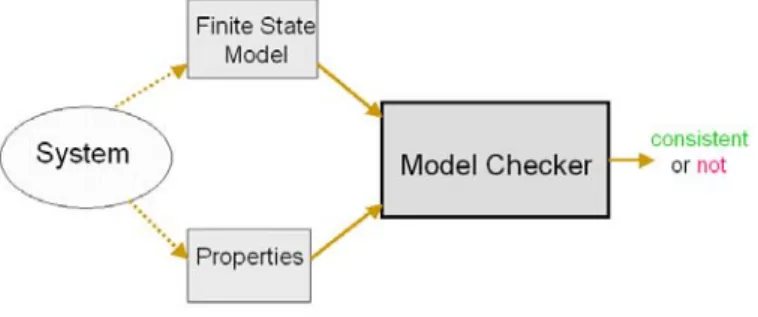
Symbolic Model Checking [10,11,14-16] is an automatic technique for verifying properties of a finite state model of a system. Its flow is illustrated in Figure 2.1.
The general approach of symbolic model checking is to describe the finite model for the behavior of the system by giving as Kripke structure, and to define the expected property of the system as Temporal Logic. It checks whether finite model satisfies the property. If not, the counterexample is generated.
2.2 Kripke Model
Kripke Model is used to model the finite state model of the system [10]. Let AP be a set of atomic proposition. A Kripke structure M over AP is a four touple M=(S, S0, R, L), where:
S
is a finite set of statesS
0⊆ S
is the set of initial statesR
⊆ S
×
S
is transition relation that must be totalL : S → 2AP is a function that labels each state with the set of atomic proposition being true in that state
2.3 State in Kripke Model
Let V = {v1, v2, … vn} be the set of system variables, the variables in V range over a finite set D.
A state of a system can be described by giving values for all of the elements in V. A state is just a valuation s : V → D for the set of variables in V. For example,
a state si is a valuation: <v1←1, v2←0, v3←1>, and thus we
derive the formula: (v1=1) ^ (v2=0) ^ (v3=1)
Figure 2.2 illustrates an example of that state in Kripke model.
[v
1, ¬v2, v3]
Fig. 2.2 A State of Kripke Model
2.4 Computation Tree
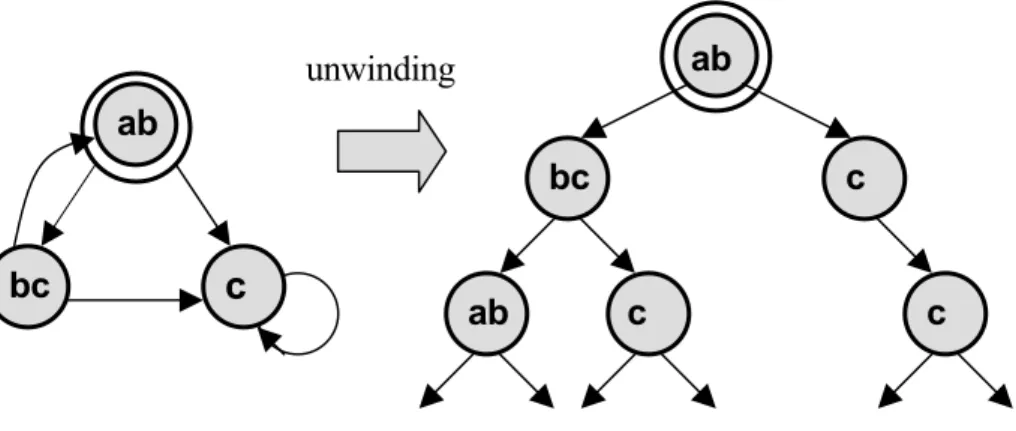
Computation tree, as illustrated in Figure 2.3, is formed by designating the initial state in Kripke structure, and then unwinding (unrolling) the structure into an infinite tree. The computation tree shows all of the possible executions starting from the initial state.
bc ab c c ab c c bc ab unwinding
2.5 Computation Tree Logics
The formulae of computation tree logics are constructed from path quantifiers and temporal operators:
1. Path quantifier:
A—“for every path” E—“there exists a path” 2. Temporal modality:
Xp—p holds next time
Fp—p holds sometime in the future Gp—p holds globally in the future pUq—p holds until q holds
Chapter 3
Proposed Approach
In this chapter, we will describe our overall approach. It is organized as the following sections. Section 3.1 defines the problem. Section 3.2 gives an input example. Section 3.3 introduces the framework. Section 3.4 determines the input language. Section 3.5 describes partitioning. Section 3.6 explains conversion techniques. Section 3.7 depicts some conversion examples. Section 3.8 elucidates verifying process. And then finally, section 3.9 demonstrates a complete example.
3.1 Problem Formulation
In our approach, the input is design assertions written in assertion language. The goal is to find out whether there are conflicts among input assertions. If yes, the approach will report which assertions are conflict and generate the counterexamples. The brief flow of our approach is illustrated in Figure 3.1.
Figure.3.1 The Brief Flow
3.2 Input Example
Here is a simple example of input assertions: Assertion-i:
assert Ai always {@a; @b; @c} => eventually {@x; @y}; Assertion-j:
assert Aj never {@b; [2:5]; @x}; Assertion-k:
assert Ak always {@a; @b; @c} before {@x; @y; @z}; Our approach will check whether there are conflicts among these assertions.
3.3 Framework
Figure 3.2 illustrates the framework of our approach to assertion checking. The proposed approach contains three portions. The first one is to partition input assertions into assertion groups. In the second portion, for each assertion group, we convert each assertion into deterministic finite automata (DFA) and their respective properties. Finally, we take those DFA and properties to run symbolic model checking. It will report contradiction and its counterexample if there is any conflict among input assertions. We will describe each portion in details in the following sections.
Checking Report
Verify DFA and Properties with SMV Convert Assertions into
DFA and Properties Partition Assertions into
Assertion Groups
Assertions
3.4 Input Language
Assertion languages for design verification such as Property Specification Language (PSL)/(Sugar) [17], OpenVera [18], and e [19,20] have been gaining in popularity and applied in industry. In order to implement our approach, we formally define an assertion language as our input assertion language. For simplicity, we choose the common set of above three popular assertion languages (PSL, OpenVera and e) as our input assertion language and call it a PSL-like language. The common set of above languages are the most frequently used common part of general design assertion languages, which is capable of modeling most of real world design properties. Our simplified PSL-like assertion language has following characteristics and assumptions:
It consists of common basic parts of popular assertion languages. It has rigorously well-defined formal semantics and concise syntax.
It cover all major temporal layer expressions and Boolean layer expressions. All primitive events are assumed clocked and synchronized.
Properties are restricted to time move forward from left to right sequentially.
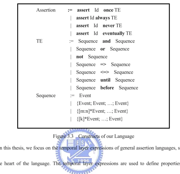
The assumption we made is only for the purpose of simplicity on implementation. It does not lose the generality of common assertion languages. The major constructs of our language are described Figure 3.3. For the syntax detail, please refer to "BNF Grammar of PSL-like Assertion Language in Appendix A.
Assertion := assert Id once TE | assert Id always TE | assert Id never TE | assert Id eventually TE TE := Sequence and Sequence | Sequence or Sequence | not Sequence
| Sequence => Sequence | Sequence <=> Sequence | Sequence until Sequence | Sequence before Sequence Sequence := Event
| {Event; Event; …; Event} | {[m:n]*Event; …; Event} | {[k]*Event; …; Event}
Figure 3.3 Constructs of our Language
In this thesis, we focus on the temporal layer expressions of general assertion languages, since this is the heart of the language. The temporal layer expressions are used to define properties, which describe Boolean expressions related over time. Temporal layer expression is sophisticated enough to describe the complex behavior of specification.
3.5 Partitioning Assertions
To alleviate the state explosion problem in formal model checking, we come up with a reduction solution. That is, we put together the assertions which share common event variables to run model checking. That is because only the assertions which have common event variables are possible to have conflict. Hence we define an assertion group for our approach. An assertion group contains some
assertion members, such that assertion members may have some common event variables. Therefore, the assertions belonging to different groups must not have any common variable.
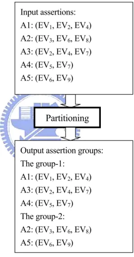
Based on this idea, all input assertions will be partitioned into several assertion groups. An example of assertion groups is illustrated in Figure 3.4, where EV are event variables.
Input assertions: A1: (EV1, EV2, EV4) A2: (EV3, EV6, EV8) A3: (EV2, EV4, EV7) A4: (EV5, EV7) A5: (EV6, EV9)
Output assertion groups: The group-1: A1: (EV1, EV2, EV4) A3: (EV2, EV4, EV7) A4: (EV5, EV7) The group-2: A2: (EV3, EV6, EV8) A5: (EV6, EV9) Partitioning
We apply the techniques in [21-23] to parse all input assertions and collect all event variables for building event variable table in the first pass. Then we partition all assertions by applying the algorithm illustrated in Figure 3.5.
Figure 3.5 The Partition Algorithm
function partition (all_assertions): for i=1 to i=N do {
for j=i+1 to j=N do {
if (Assertion j is not empty) do {
if (Assertion i and Assertion j have common event variables) do { Assertion i := Assertion j ∪ Assertion j;
Assertion j := ∅; };
}; };
if (any_merger_happened) do {
swap(Assertion i, Assertion last_merged ); Assertion i := ∅;
}; }; };
As the shown pseudo code in the Figure 3.5, the assertions which have common variables will be put together.
By partitioning the assertions, the runtime of symbolic model checking is greatly reduced. Furthermore , the time complexity of this algorithm is O(N2). In most real cases, the assertions may be
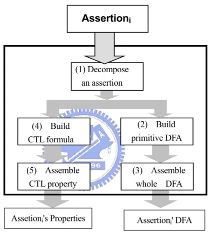
3.6 Assertion Conversion Techniques
The essential part of our approach is assertion conversion. After partitioning assertions, each assertion is converted into a deterministic finite automata (DFA) and its corresponding CTL property. The process is illustrated in Figure 3.6.
(4) Build CTL formula Assertioni' DFA Assetioni's Properties
Assertion
i (5) Assemble CTL property (3) Assemble whole DFA (2) Build primitive DFA (1) Decompose an assertionFigure 3.6 The Conversion Process
Before the conversion routines work, we derive the conversion templates for various assertion types and temporal operators. These templates facilitate the conversion work in the later processes. In the conversion process, the first step is to decompose the assertions into primitive sequences and to extract temporal operators. We also determine the assertion types by those decomposition and extraction.
Then the second step is to build primitive DFA. Since the assertion type and temporal operator have been known from the first step, we may decide which type to apply. In this step, the primitive sequence is also decomposed further into the passive part and/or active part.
For example, consider a part of an assertion, {@a; @b} => {@x; @y}. We define the left hand side ({@a; @b}) of the temporal operator as the passive part; the right hand side ({@x; @y}) as the active part. Once the premise condition is matched, the consequence sequence will be forced to hold. The events with active attribute in that sequence will be forced to occur. So those events should be actively driven. In terms of event correlation and contribution of stimulation for asserted argument, the event attribute of an assertion is also determined by both assertion type and temporal operator. The attribute categories are listed in Table 3.1.
Active
eventually Seq. eventually Seq. and/or/not Seq.Proactive
always Seq. always Seq. and/or/not Seq.C
(pa
o-active
ssive-active)
always Seq. => Seq. always Seq. <=> Seq. always/once Seq. before Seq. always/once Seq. until Seq.
A
ttr
ib
ute
s
Passive
never Seq. never Seq. and/or/not Seq.once Seq.
once Seq. and/or/not Seq. Table. 3.1 Event Attributes
The third step is to assemble the whole composite DFA. The composite DFA is a structural DFA which is constructed by combining DFA according to assertion type and temporal operators.
The fourth step is to build Computation Tree Logic (CTL) formula. The primitive CTL formula are constructed from path quantifiers and CTL temporal modalities. The atomic proposition is directly extracted and converted from the events of original assertion. The proposition whose events have passive attribute will be specified with the "E" path quantifier because they are free event variables in that property. That means the event value depends on the path in the computation tree. On the contrary, the proposition whose events have active attribute will be specified with "A" path quantifier because their value is constrained to specific ones for the all paths. Temporal modalities in CTL are also determined by original temporal operator and assertion types. For example, if it is an atomic event of a sequence holding at the next time, just specify its temporal modality as "X".
The final step is to assemble the whole property by combining the CTL formula which were converted at previous steps and the logical connectives which are determined according to the assertion type. At the end, we get the DFA and the corresponding property by above conversion steps.
We explain the correctness of assertion conversion in our approach in Appendix B.
3.7 Conversion of Common Types of Assertions
According to assertion type and temporal operator, we pre-build the conversion templates which are used in conversion steps. In this section, we depict how to build such conversion templates for some most common used temporal operator or the assertions which use these operators.
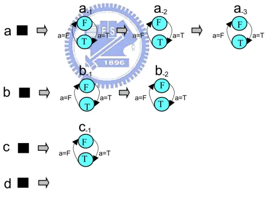
3.7.1 Conversion Template of "sequence" Operator
Definition: A sequence is a finite series of events that represent a set of sequential behaviors, which is enclosed in curly braces.
Example: {@a; @b; not@c; @d};
Converted DFA in SMV:
As in Figure 3.7 (a), we create the leave DFA of each event variable for current state and previous states, which keep the current event states and the previous states.
a=T a=F T F
a
-2 a=F T Fa
-1 a=T F Ta
-3 a=F a=Ta
T Fb
-1 a=T Tb
-2 F a=Tb
a=F a=F F Tc
-1 a=Tc
a=Fd
Then, we construct the composite DFA by combining those leave DFA. It is illustrated in Figure 3.7 (b).
b
a
c
-1b
-2a
-3b
-1a
-1a
-2 {@a
; @b
; not@c
; @d
}c
d
Figure 3.7 (b) The Converted Composite DFA
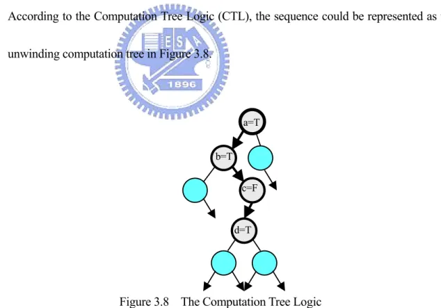
Converted Property in SMV:
According to the Computation Tree Logic (CTL), the sequence could be represented as the unwinding computation tree in Figure 3.8.
d=T c=F b=T
a=T
Figure 3.8 The Computation Tree Logic
Therefore, we can describe its property with CTL formula the following:
3.7.2 Conversion Example of "sequence-imply-sequence" Operator
We demonstrate an example of conversion template of sequence-imply-sequence. The conversion steps are depicted in following respective figures.
Assertion example: always {@a; @b; @c} => {@x; @y} Converted DFA in SMV:
Step 1 is to decompose the assertion into primitive sequences, they are {@a; @b; @c} and {@x; @y}, and temporal operator "=>".
always {@a; @b; @c} => {@x; @y}
always {@a; @b; @c} => {@x; @y}
Main temporal operator Primitive sequence with passive attribute Determine the assertion type bythe assertion keyword "always" and the main temporal operator
Primitive sequence with active attribute
Figure 3.9 Decomposing The Assertion
The step 2 is to build primitive DFA. In Figure 3.10 (a), the primitive sequence {@a; @b; @c} with passive attribute is converted into a leave DFA.
b
-1a
-2a
-1b
a
{@a; @b; @c}c
is shown in Figure 3.10 (a). The composite DFA is shown in Figure 3.10 (b). {@a;@b;@c}
not{@a;@b;@c}
not{@a;@b;@c}
i
{@a;@b;@c}abc
Figure 3.10 (b) The Converted Composite DFA
On the other side, the primitive sequence {@x; @y} with active attribute is converted into a leave DFA, which is shown in Figure 3.10 (c)
x
y
x ← 1 y ← 1
Figure 3.10 (c) The Converted DFA
In step 3, we assemble the whole composite DFA. The composite DFA is assembled by composing some leave DFA. The assembled DFA is illustrated in Figure 3.11.
The passive part The active part
y ← 1 x ← 1
x
y
not{@a;@b;@c} {@a;@b;@c} not{@a;@b;@c}i i
abc
Converted Property in SMV:In step 4, we build CTL formula for each decomposed primitives. The respective converted CTL is shown in below.
always {@a; @b; @c} => {@a; @y};
EX(a=T & EX(b=T & EX(c=T -> AX(x=T & AX(y=T)) )));
In this case, we apply the CTL temporal modality "X" for each events of sequences, because they are the continuous next events in a sequence. For the passive sequence, the "E" quantifier is specified due to there is some path for which the sequence matching codition (@a; @b; @c) holds. On the contrary, for the active sequence, the "A" quantifier is specified since it holds for every paths once the condition matched.
In step 5, we assemble the whole CTL property by combining the primitive CTL formula which are converted in step 4. The converted CTL property is illustrated in Figure 3.12.
SPEC EG (a=T & EX(b=T & EX(c=T
-> AX(x=T & AX(y=T)) ))) ;
Figure 3.12 Assemble CTL Property
The final converted CTL property for this example is:
3.7.3 Conversion Example of "and" Operator
In the following section, we demonstrate the conversion results, but omit the conversion details. Definition: An expression with length-matching "and" operator succeeds when both compound TE hold at the current cycle, and furthermore both complete in the same cycle. Example: {@a; @b; @c} and {@p; @q; @r}
Converted DFA in SMV: {@a; @b; @c} and {@p; @q; @r} {@p; @q; @r} {@a; @b; @c}
a-2
b-1
p-1
a
-1q-1
p-2
r
q
p
b
c
a
Figure 3.13 Converted DFA
Converted property in SMV:
3.7.4 Conversion Example of "or" Operator
Definition: An expression holds on a path iff at least one of events/sequences holds on the path. Example: {@a; @b; @c; @d} or {@p; @q} Converted DFA in SMV: {@a; @b; @c; @d} {@a; @b; @c; @d} or {@p; @q} {@p; @q}
Figure 3.14 Converted DFA
Converted properties in SMV:
SPEC EF(a=T & EX(b=T & EX(c=T & EX(d=T))) | (p=T & EX(q=T)));
3.7.5 Conversion Example of "until" Operator
Definition of “@a until @b”: It holds in the current cycle iff: 1) @b holds at the current cycle or at some future cycle and 2) @a holds at all cycles up to and including the earliest cycle at which @b holds.
We add an additional state named as "Fail" in the converted DFA. When it enters the "Fail" state, it means it violates the assertion.
Figure 3.15 Converted DFA
Converted properties in SMV
SPEC A[a=T U b=T]
or
SPEC !EF state=Fail;
3.7.6 Conversion Example of "before" Operator
Example: always @a before @b;
Converted DFA in SMV:
Converted properties in SMV:
3.7.7 Conversion Example of "repetition" Operator
repetitions of the repeat-expression such that the number falls
Example: {@a; [2:4]; @c}
Converted DFA in SMV
igure 3.17 Converted DFA
V:
Definition: any number of within the specified range.
t
4 c=F c=T a=Ta
t
1t
2t
3 c=Fi
F a=T c=F Converted property in SM c=T c=TSPEC !EF state=Fail;
or
SPEC !EF(((a=F & b=T) & EF(a=T)) |
((a=F & b=F) & EG((a=F & b=F) & EF(a=T & b=T))));
SPEC =T & EX(EX(EX(c=T | EX(c= EX(c=T))))));
c
a=F a=F
T| EF(a
3.7.8 Conversion Example of "eventually" Operator
@c} => eventually {@x; @y}
C
Converted Property in SMV
The operator, "eventually" means that the property holds at the current cycle or at some future cycle. That is it must hold at some time in the indefinite future. To implement the checking for this assertion, we have SMV to assign value non-deterministically until it reaches the specified time upper bound. That means the assertion will hold at most of upper limit time. According to the analysis, this upper bound should be greater than the maximum depth of time step of all input assertions. That ensures the assertion will be held in finite time.
Figure 3.18 Converted DFA
SPEC EF(EG(a=T & EX(b=T & EX(c=T & AF(x=T & AX(y=T))))));
Example: always {@a; @b; onverted DFA in SMV:
a
b
c
{@a; @b; @c} {@a; @b; @c} not{@ @b; @c} "eventually" timeouta
-1a
-2b
-1 not{@a; @b; @c}i
abc
xy
x←T; y←T not{@a; @b; @c} {@a; @b; @c}3.8 Verifying Assertions with SMV
After assertion conversion finishes, we apply symbol model verifier (SMV) to verify converted asse s the converted set of DFA and set of properties are fed to SMV. If
ny conflict exists, the verifier will report the counterexample. Figure 3.19 illustrates the process.
3.9 A More Complete Example of Assertion Checking
In this section, we use a complete example to demonstrate our approach, and explain its process step by step. First at all, as shown in Figure 3.20, there are six assertions in the input.
rtion . For each assertion group, a
assert A1 always {@a; @b; @c} => ev
In our approach, we partition the input assertions into assertion groups. According to the partitioning algorithm, the six are assertions are partitioned into two groups, Assertion Group 1 and Assertion Group 2, as Figure 3.21 shows.
mposed into primitive se
entually {@x; @y;@z}; assert A2 eventually {{@m; [2:5]*@n; @o} or {@p;@q}};
assert A4 once {{[2]*{@m; @n; @o}} and {[2]*{@p; @q; @r}}}; assert A6 always (@a or @b) => {[3]*@w; @x};
assert A3 never {@b; [2:5]; @x};
assert A5 always {@a; @b; @c} before {@x; @y};
Figure 3.21 Partitioning Result Figure 3.20 Input of the Example
Assertion Group 1:
assert A1 always {@a; @b; @c} => eventually {@x; @y; @z}; assert A3 never {@b; [2:5]; @x};
assert A5 always {@a; @b; @c} before {@x; @y}; assert A6 always (@a or @b) => {[3]*@w; @x};
Assertion Group 2:
assert A2 eventually {{@m; [2:5]*@n; @o} or {@p; @q}};
assert A4 once {{[2]*{@m; @n; @o}} and {[2]*{@p; @q; @r}}};
We take Assertion Group 1 to demonstrate the process. In the step 1, it is deco
quences and temporal operators, and the conversion template is applied according to the decomposed result. It is illustrated in Figure 3.22.
Then at step 2, the primitive DFA are built according to decomposed primitive sequence . At step3, composite DFA is assembled by each primitive DFA and temporal operators. The converted DFA of Assertion Group 1 is depicted in Figure 3.23.
Similarly, assertion A3, assertion A5 and assertion A6 are shown in the Figure 3.24, 3.25 and 3.26 respectively.
Figure 3.23 Converted DFA from Assertion A1
A1: always {@a; @b; @c} => eventually {@x; @y; @z};
abc
xyz
; @c} not{@ @b; @c} "eventually" timeout not{@a; @b; @c} x←T; y←T; z←Ti
{@ @b; @c} {@a; @b not{@ @b; @c}Figure 3.22 Decomposed Assertions of Assertion Group 1 y; @z};
x}; assert A1 always {@a; @b; @c} => eventually {@x; @ assert A3 never {@b; [2:5]; @x};
assert A5 always {@a; @b; @c} before {@x; @y}; assert A6 always (@a or @b) => {[3]*@w; @
Figure 3.24 Converted DFA from Assertion A3
Figure 3.25 Converted DFA from Assertion A5
Figure 3.26 Converted DFA from Assertion A6 A3: never {@b; [2:5]; @x}; b=F x=F x=F
i
b
t
1t
t
t
fail
b=Tt
x=F 2 3 4 5 x=T x=T x=T x=TA3: always {@a; @b; @c} before {@x; @y};
abc
xyz
i
fail
{@a; @b; @c} not{@ @b; @c}
not{@a; @b; @c } & not{@x; @y}
{@x; @y} {@x; @y} c } & not{@x;
w
x
b
a
w
i
w
x←T w←T not(@ a or @b) a=T a=TA6: always (@a or @b) => {[3]*@w; @x};
@y} {@a; @b; @
At the step 4 and step 5, CTL formula are built and then properties are assembled with them. The onverted properties are illustrated in the following.
After the conversion is done, the converted DFA and properties are fed into SMV for checking. The port is shown in Figure 3.27.
As the Figure 3.27 shows, there are four conflicts found in this assertion group. They are DFA1
gainst Property3, DFA1 against Property5, DFA3 against Property6, and DFA6 against Property3.
ccording to our analysis from the checking results of SMV, where (DFA1,Property3) and
(DFA Property) are unilateral conflict, so they are suspected conflicts alert. That means it could be Property of assertion A1:
SPEC !EF(EG(a=T & EX(b=T & EX(c=T & !AF(x=T & AX(y=T & AX(z=T))))));
Property of assertion A3:
SPEC !EF(b=T & EX(EX(EX(x=T | EX(x=T | EX(x=T | EX(x=T)))))));
Property of assertion A5:SPEC !EF state=Fail; Property of assertion A6:
SPEC EG((a=T | q=T) -> AX(w=T & AX(w=T & AX(w=T & AX(x=T)))));
c
re
Conflicts found:
DFA1
↔Prop3 conflicted
DFA1
↔Prop5 conflicted
Conflicts found:
DFA3
↔Prop6 conflicted
DFA6
↔Prop3 conflicted
Unilateral conflicts, suspected conflicts alerted
Mutual conflicts, definite conflicts reported
Figure 3.27 Checking Result
a A
ind
rtions. The other two, (DFA3, Property6), are
m lict. That means they are definite conflicts.
eed conflict or either one of two is redundant. Therefore, users who perform our approach can inspect the result to identify the errors among the asse
Chapter 4
Case Study
4.1 Case Description
We choose the assertions for the Bus Transaction Protocol of PCI Local Bus Specification as our case. The assertions cover Bus Transfer Control, Addressing, Byte Lane and Byte Enable, Bus Driving and Turnaround, as well as Transaction Ordering and Posting [26].
In general, the assertions consist of two parts: PCI master and PCI target. There are 41 assertions in this case study.
4.2 Experimental Environment
We implement our approach in C program and some shell scripts. They are executed on Sun Sparc Workstation with 1 GB memory on 400MHz speed.
4.3 Experimental Result
We partition the input assertions into 5 and 4 assertion groups for PCI master and PCI target pectively.
ected conflicts alerted), 1 mutual conflicts, (definite conflicts reported). The experimental result is depicted on Table. 4.1.
Case No. of Assertions No. of Assertion Groups No. of Unilateral Conflicts No. of Mutual Conflicts Runtime (by second) res
After execution, it found:
4 unilateral conflicts (susp
PCI Master 25 5 2 1 92
PCI Target 16 4 1 0 41
Chapter 5
Conclusions and Future Works
5.1
ions
We check esign assert by means of converting assertion into
corresponding DFA and pr the others using SMV.
The major features of our approach are:
Without referring the design, only the assertions required, Without need of simulation and test patterns,
Stand-alone, off-line processing, may check assertions prior to design verification, Greatly alleviating the state explosion problem of SMV.
operties and then checking each of them against
Conclus
5.2 Discussion
Ensuring a set of assertions without any conflict can increase our confidence in the correctness of specification modeling. Not necessary all potential conflicts could be found by using our approach. onflicts are guaranteed to be definite conflicts. According to our experience, we found it is hard to detect redundancy of assertions merely by static formal checking
m assertions.
of correlation stimulation of assertions under certain combinations in the input assertions. Under this cumstances, the assertions cannot contribute stimulus correlation to argue against each others. For
rtions in an assertion group illustrated below.
Even and @c), but the two assertions
are b nnot contribute stimulation for each other. It
revea rrelative.
That
Furthermore, the definition of our acceptable input assertion language must be very clear and definite without any ambiguity; otherwise, it tends to induce problem caused by different interpretation the
But all detected mutual assertion c
fro
The most serious hurdle to apply this approach to find out all possible conflicts is lack
cir
example, there are two asse
assert never {@a; @b; @c};
assert never (@a; and @b) or (@a and @c);
the above two assertions share all common variables (@a, @b oth with the same "passive" attribute. So they ca
ls that the ideal input set is the assertions with variety of event attributes and highly co provides enough assertive statement against each others.
of language.
As for the computational complexity, our experiences showed that runtime is acceptable for up to hundreds of input assertions in an assertion group.
In summary, symbolic model checking, in its purest basis at least, is feasible to apply conflict checking for assertion without design model and test patterns. Even it is more difficult than anticipated during the developing process, particularly on coping with versatile combination of input assertions, the
ctions such as Logic Reasoning techniques may be considered to enhance our apability of checking. Next, we will input the simulation results or waveforms to augment the formation about assertions. By this way, we can clearly identify conflicts and redundancy among idea has been shown conceptually correct and furthermore this approach could be practically implemented for the industrial usage.
5.3 Future Works
Some research dire
c
in
assertions and also check assertion violations.
Furthermore, by adding certain converting process, we may convert counterexample of SMV into industrial standard Value Change Dump (VCD) format. That information can help user quickly identify the problem pointed out by SMV.
As for input language, we should accept the full set of common-used language by enlarging the conversion templates for remaining types of that language constructs and enriching the conversion rules for all temporal operators.
A
Grammar of PSL-like Assertion Language
Compilation := Assertion_Collection
ppendices
Appendix A: The BNF
; Assertion_Collection := Assertion | Assertion_CollectionAssertion ;Assertion := "assert" Assertion_NameTemporal_Assertion_Kinds ";" ;
Assertion_Name := IDENTIFIER ;
Temporal_Assertion_Kinds := Once_Assertion | Always_Assertion
| Never_Assertion
| Eventually_Assertion ;
Once_Assertion := "once" Temporal_Or_Expression
| "once" Temporal_And_Expression "until" Temporal_And_Expression ; Always_Assertion := "always" Temporal_Or_Expression
| "always" Temporal_Or_Expression "=>" Temporal_And_Expression
| "always" Temporal_Or_Expression "=>" "eventually" Temporal_And_Expression
| "always" Temporal_And_Expression "<=>" Temporal_And_Expression
| "always" Temporal_And_Expression "before" Temporal_And_Expression ; Never_Assertion := "never" Temporal_Or_Expression ;
Eventually_Assertion := "eventually" Temporal_Or_Expression ; Temporal_Or_Expression := Temporal_And_Expression
| Temporal_And_Expression "and" Temporal_Compound_Expression ; mporal_Compound_Expression := Temporal_Repeat_Expression Te | "not" Temporal_Compound_Expression ; Temporal_Repeat_Expression := Temporal_Primitive | Repaet_TimesTemporal_Repeat_Opt | Repaet_Times ; epaet_Times := "[" Repaet_Range"]" um R | "[" Repaet_N "]" ; INTLITERAL Repaet_Range := ":" INTLITERAL ; epaet_Num := INTLITERAL R ; emporal_Repeat_Opt := "*" Temporal_Compound_Expression T ; Temporal_Primitive := Event | "(" Temporal_Or_Expression ")" | "{" Temporal_Sequence "}" ; Temporal_Sequence := Temporal_Or_Expression | Temporal_Sequence ";" Temporal_Or_Expression ; Event := "@" Event_Name ; Event_Name := "CYC" | IDENTIFIER ;
IDENTIFIER := Letter(Letter|Digit|_)* ;
TLITERAL := Digit
IN + ;
etter := [A-Za-z] ;
L
Appendix B: Proving of Assertion Conversion
The conversion processing of our approach consists of two parts. One is converting assertion to CTL property. The correctness of this part is comprehensive. Since PSL-like language and CTL property have similar temporal semantics in temporal specification in terms of language feature. The other is converting assertion into DFA. The most crucial part in our approach is assembling the whole DFA with pieces of DFA. Now, we would like to explain its correctness below.
1. A sequence is part of language clause which follows regular expression grammar (RE grammar).
2. Sequences and sequence operators belong to regular language set.
3. A temporal expression can be decomposed to primitive sequences and operators. 4. By Kleene’s Theorem, each primitive sequence has its corresponding finite automaton.
5. A larger finite automaton can be composed of pieces of small finite automata by applying our approach which belong to operations of RE grammar.
6. So, the combined larger finite automaton can represent the collection of DFA pieces which are converted from original assertion.
Why assembling a composite DFA from piece sequences in our approach is correct in theory? Let's explain it in more detail. First of all, we may see that the most primitive item operated by our approach is a sequence, which describes single- or multi-cycle behavior built from a series of Boolean
expressions over time. The most atomic is a Boolean expression. In Property Specification Language SL), the sequence named as Sequential Extended Regular Expressions (SEREs)[24], that extends the
is part of the regular lang
concate nion, and repetition which follow regular expression definition.In our approach, we
dec heorem in formal language,
wh utomaton, or
tran o , every
lang
means primitive sequence. This is just what we
do
DFA w the composing rule which belong to regular expression set.
(P
set of regular expression (RE) by definition for some additional temporal operations.
A sequence defined in our language is same as the sequence in PSL except pruning out some non-necessary sequence operations without losing capability for behavior specification. It keeps all our operations applied on sequences belonging to regular expression set.
By definition from formal languages, a sequence of our PSL-like language
uage grammar, which is also a context free grammar. The basic operations in our approach are nation and u
ompose an assertion down to some primitive sequences. By Kleene’s T
ich states that any language which can be defined by regular expression, or finite a siti n graph can be defined by all three methods. It implies the subordinate proposition
uage that can be defined by a regular expression can also be defined by a finite automaton. That we can find a corresponding finite automaton for each
to convert primitive sequence to a piece finite automaton. Then, we assemble the whole composite ith those primitive DFA by applying
So, the composed larger DFA can represent the collection of DFA pieces, and which are converted from the original assertion. Then, we can prove our approach is correct.
Bibliography
[1] Thomas Kropf, and Robert Bosch GmbH, “Introduction to Formal Hardware Verification”, Springger-Verlag Berlin Heidelberg, Germany, 1999.
[2] Harry D. Foster, "Property Specification: The Key to an Assertion-Based Verification Platform", Verplex Systems, Inc., 2000.
[3] Harry D. Foster, Adam C. Krolnik, and David J. Lacey, “Assertion-Based Design “ 2nd ed., Kluwer Accademic Publishers, 2004.
[4] Ben Cohen, “Using PSL/Sugar with Verilog and VHDL, Guide to Property Specification Language for ABV”.
[5] Carnegie Mellon University, http://www-2.cs.cmu.edu/~modelcheck/.
[6] ITC-IRST, Trento, Italy; SCS, Carnegie-Mellon University, Pittsburgh, PA, USA; DSI, University of Milano, Milano, Italy, "NuSMV: a new Symbolic Model Verifier",
http://nusmv.irst.itc.it/NuSMV/papers/cav99/html/index.html.
[7] Roberto Cavada, Alessandro Cimatti, Emanuele Olivetti, Gavin Keighren, Marco Pistore and Marco Roveri, "NuSMV v2.2 User Manual", http://nusmv.irst.itc.it/NuSMV/.
[8] Roberto Cavada, Alessandro Cimatti, Gavin Keighren, Emanuele Olivetti, Marco Pistore, and Marco Roveri, "NuSMV 2.2 Tutorial", http://nusmv.irst.itc.it/NuSMV/.
[9] K. L. McMillan, "The SMV language", Cadence Berkeley Labs version of SMV, http://www.cis.ksu.edu/santos/smv-doc/language/language.html.
0] Edmund M. Clarke, Orna Grumberg, and Doron A. Peled, “Model Checking”, The MIT Press,
[11] Model Checking”, Kluwer Academic
[12] Robert C. Koons , “Doxastic Paradox and Reputation Effects in Iterated Games”, Proceedings of the
[13] ong, and Melissa Smartt, “Assertional Checking and Symbolic
ER, January 1979.
tons for Branching Time
[15] oncurrent Systems in CESAR", In
[1
Cambridge, 1999.
Kenneth L. McMillan, Edmund M. Clarke, “Symbolic Publishers, 1993.
4th conference on Theoretical aspects of reasoning about knowledge, March 1992. J. Mack Adams, James Armstr
Execution: An Effective Combination for Debugging”, Proceedings of the 1979 annual conference,
ACM/CSC-[14] E. M. Clarke and E. A. Emerson, "Synthesis of Synchronization Skele
Temporal Logic", in logic of programs: workshop, Yorktown Heights, NY, May 1981, volume 131 of Lecture Notes in Computer Science.Springer-Verlag, 1981.
J.P. Quielle and J. Sifakis, "Specification and Verification of C
Proceedings of the Fifth International Symposium in Programming, volume 137 of Lecture Notes in Computer Science.Springer-Verlag, 1981.
[16] Thomas Kropf, "Formal Hardware Verification - Methods and Systems in Comparison", Springger-Verlag, Berlin Heidelberg, Germany, 1997.
[17] Accellera Organization, "Property Specification Language Reference Manual", V 2004.
ersion 1.1, June 9,
[19] ., “e Language Reference Manual” V4.3, 2004,
[20] esign Verification with e", Prentice Hall Modern Semiconductor Design Series,
[21]
[23] GNU, "Flex reference Manual", Version 2.5.31, GNU, Free Software Foundation, Inc.,, 27 March
[24]
[25] rd Ed., 2001.
[18] Synopsys, Inc., "OpenVera 1.0 Language Reference Manual Version 1.0", March 2001. Verisity Design, Inc
(http://www.ieee1647.org/downloads/prelim_e_lib.pdf) Samir Palnitkar, "D
2003.
Charles N. Fischer, Richard J. LeBlanc, Jr., “Crafting A Compiler with C”, 1991.
[22] GNU, "Bison reference Manual", version 1.875, GNU, Free Software Foundation, Inc., 28 December 2002.
2003.
Daniel I. A. Cohen, “Introduction to Computer Theory", 2nd Ed., Oct. 25, 1996. Peter Linz, "An Introduction to Formal languages and Automata", 3
Vita
ia-YuaCh n Uang receiverd the B.S. degree in electronics engineering from National Taiwan Institute
T aboratories
(C with Maojet Technology Corp.
from 1 tion, RTL synthesis, and timing analysis.
echnology. From 1989 to 1996, he worked for Computer and Communications Research L CL) of Industrial Technology Research Institute (ITRI). He has worked