國立交通大學
電子工程學系 電子研究所
碩 士 論 文
分散式暫存器檔案架構之資料傳輸合成
Communication Synthesis on
Distributed Register-File Microarchitecture
研 究 生:林彥廷
指導教授:黃俊達 博士
分散式暫存器檔案架構之資料傳輸合成
Communication Synthesis on
Distributed Register-File Microarchitecture
研究生:林彥廷 Student: Yen-Ting Lin
指導教授:黃俊達 博士 Advisor: Dr. Juinn-Dar Huang
國立交通大學
電子工程學系 電子研究所
碩士論文
A Thesis
Submitted to Department of Electronics Engineering & Institute of Electronics College of Electrical & Computer Engineering
National Chiao Tung University in Partial Fulfillment of the Requirements
for the Degree of Master
in
Electronics Engineering & Institute of Electronics
July 2009
Hsinchu, Taiwan, Republic of China
分散式暫存器檔案架構之資料傳輸合成
研究生:林彥廷 指導教授:黃俊達 博士
國立交通大學
電子工程學系 電子研究所碩士班
摘 要
進入深次微米時代,過長的連線導致過大的延遲,使得系統的效能難以繼續提高。 數種分散式暫存器架構被提出,企圖使用較短的區域連線進行大部分的資料傳輸,以解 決延遲的問題。最近,一種名為分散式暫存器檔案的架構被提出,此架構將系統分為數 個構造相同的島,而島間連線數目被用作設計早期階段評估系統好壞之指標。這篇論文 提出一個合成流程,在分散式暫存器檔案架構上,將島間連線數目減到最少。首先,使 用反覆綁定和重新排程之技巧,得到比先前作品更好的結果;接著,資料傳輸被重新規 劃,使得島間連線數目能更進一步減少。由實驗結果得知,與前作相比,我們可以將島 間連線數目減少達百分之二十四。Communication Synthesis on
Distributed Register-File Microarchitecture
Student: Yen-Ting Lin Advisor: Dr. Juinn-Dar Huang
Department of Electronics Engineering & Institute of Electronics
National Chiao Tung University
Abstract
In deep-submicron era, global interconnect delay has become the bottleneck while pursuing higher system clock speed. Several distributed register (DR) architectures have been proposed to cope with this problem by keeping most interconnects local. The recently proposed distributed register-file microarchitecture (DRFM) is one of the DR-based architectures. On DRFM, the number of inter-island connections (IICs) is used as an evaluation metric for quality of results in early design phases. This thesis proposes a two-phase resource-constrained communication synthesis algorithm for IIC minimization targeting DRFM. First, an iterative binding-then-rescheduling procedure is used to obtain a better outcome in the expanded solution space. Then, a data detouring procedure is utilized to further minimize the number of IICs. The experimental results show that an average of 24% IIC reduction can be achieved as compared to the previous work.
誌 謝
首先,我要感謝我的指導教授-黃俊達博士,在碩士兩年當中給我的支持和鼓勵, 讓我能有良好的研究環境,在自由的學習風氣之下,培養出獨立研究的能力,又能隨時 給予寶貴的意見及指導,對老師的感激之情,並非以簡短的文句可以表達。 當然也要感謝養育我長大的父母對我的栽培,沒有他們,就沒有今日的我。接著 要感謝的是所有來參與口試的所有教授們,黃婷婷教授、周景揚教授和張世杰教授,百 忙當中抽空前來指導我,讓我受益匪淺,也讓我得到了寶貴的經驗,謝謝你們。 我也要感謝實驗室的同學、學長姐和學弟妹,跟大家一起修課、做實驗和討論及 分析研究成果更是我人生旅途中一段最值得珍惜的回憶,希望未來在讀書或工作還有機 會一起努力。 希望這篇論文能對人類社會有小小的貢獻,如此一來再辛苦也就值得了,再次謝謝 大家的幫忙。Contents
Abstract (Chinese) ...i
Abstract (English)...ii Acknowledgement ... iii Contents ... iv List of Tables ... vi List of Figures...vii Chapter 1 Introduction... 1
Chapter 2 Related Works and Motivations ... 4
2.1 Distributed Register Architecture...4
2.2 Regular Distributed Register Microarchitecture...5
2.3 Distributed Register-File Microarchitecture... 6
2.4 Motivational Examples... 8
2.4.1 Effects of Scheduling... 8
2.4.2 Data Detouring ... 8
2.4.3 Read Port Limitation ... 9
Chapter 3 Proposed Algorithm ... 11
3.1 Overview ...11
3.2 IIC Refinement ... 13
3.3 Data Detouring ... 16
Chapter 4 Experimental Results ... 22 Chapter 5 Conclusion ... 28 References ... 29
List of Tables
Table 1: Gains and partial gain sums in an iteration ... 15
Table 2: The basic information of benchmarks ... 24
Table 3: Experimental results of configuration 1 (w/o read port limitation)... 26
Table 4: Experimental results of configuration 2 (w/o read port limitation)... 26
Table 5: Experimental results of configuration 3, #read_ports = 2 ... 27
List of Figures
Fig. 1: Delay versus feature size... 1
Fig. 2: The island architecture of DRFM ... 2
Fig. 3: Distributed register architecture... 4
Fig. 4: 2 × 3 island-based RDR microarchitecture ...5
Fig. 5: A scheduled and bound DFG ... 6
Fig. 6(a): The scheduled DFG ... 8
Fig. 6(b): The scheduled and bound DFG ... 8
Fig. 6(c): The rescheduled and bound DFG ... 8
Fig. 7(a): The schedule and bound DFG with bubbles... 9
Fig. 7(b): The scheduled and bound DFG after data detouring... 9
Fig. 8(a): A scheduled and bound DFG... 10
Fig. 8(b): The same DFG with another scheduling ... 10
Fig. 9: The overall flow of the proposed algorithm... 11
Fig. 10(a): The DFG at the beginning of the iteration... 14
Fig. 10(b): The DFG at the end of the iteration... 14
Fig. 11(a): The splittable and non-splittable IITs ... 16
Fig. 11(b): The resultant DFG after data detouring... 16
Fig. 12: Two key steps of the data detouring procedure ... 17
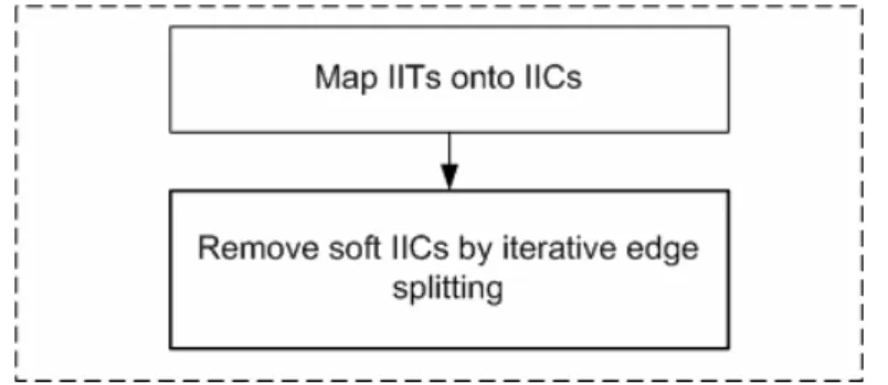
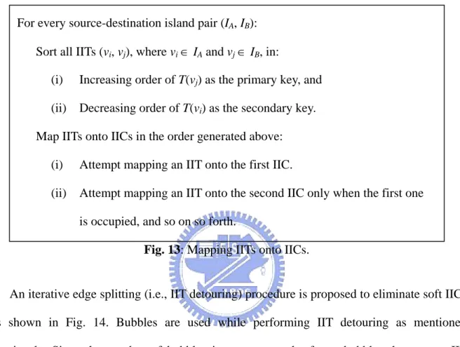
Fig. 13: Mapping IITs onto IICs... 18
Fig. 15: The detouring graphs for (a) IIT1,7 , (b) IIT2,8 and (c) IIT5,10... 19
Fig. 16: Experimental flows w/o read port limitation ... 25 Fig. 17: Experimental flows w/ read port limitation ... 25
Chapter 1
Introduction
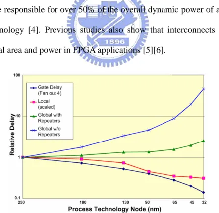
Interconnects have become a crucial factor for electronic circuits and systems as IC technology advances into the deep-submicron era. In particular, global interconnects significantly affect the performance, area and power dissipation of modern systems [1]–[3]. The graph shown in Fig. 1 indicates that the interconnect delay, especially the global one, does not decrease well when the feature size shrinks. Furthermore, It is reported that interconnects are responsible for over 50% of the overall dynamic power of a microprocessor in 130 nm technology [4]. Previous studies also show that interconnects overwhelmingly dominate the total area and power in FPGA applications [5][6].
Several approaches have been proposed to deal with the critical issue arising from long interconnects. Globally-asynchronous locally-synchronous designs adopt handshaking
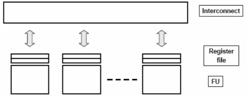
protocols for communication between different modules over long interconnects [7]. In a synchronous latency-insensitive system, special pipelining elements, named relay stations, are inserted to break long interconnects into short segments so as to sustain high operating frequency [8]. In addition, several kinds of distributed register (DR) architectures, in which systems are divided into several logic clusters, are also broadly studied [9]–[20]. Generally speaking, all DR-based architectures try to keep interconnects local within a cluster, and thus minimize the required number of long inter-cluster interconnects for better performance and smaller area.
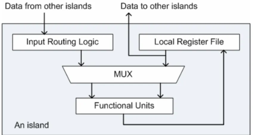
A DR-based architecture called distributed register-file microarchitecture (DRFM) was recently proposed in [9]. DRFM consists of multiple islands, each having a local register file, functional units (FUs) and data-routing logic, as shown in Fig. 2. Also, it is particularly adequate for platforms with rich distributed memory or register-file blocks, e.g., modern FPGAs. On DRFMs, the total number of inter-island connections (IICs) is regarded as an evaluating metric for quality of results (QoR) in early design phases because of its high correlation with the area and performance of synthesized designs [9]. Hence, a resource binding algorithm was also proposed in [9], and the goal was to minimize the number of IICs.
In this thesis, we propose a new resource binding algorithm targeting DRFM for minimization of the number of IICs and the latency of systems. Given a data flow graph
(DFG) and a resource constraint (i.e., number of islands), an iterative binding-then-rescheduling procedure is performed. At each control step (cstep), operations scheduled at this cstep are appropriately assigned to islands first, and then a simultaneous rescheduling and rebinding technique is used to get better solutions in terms of the number of IICs and to avoid read port access conflicts of register files. After the iterative procedure, a data-detouring one via edge splitting is utilized for further IIC minimization.
The rest of this thesis is organized as follows. The related works and motivations are discussed in Chapter 2. Chapter 3 presents the detail of our proposed algorithm for DRFM synthesis. Experimental results and analysis are given in Chapter 4, followed by conclusions in Chapter 5.
Chapter 2
Related Works and Motivations
2.1 Distributed Register Architecture
Conventionally, centralized register (CR) architectures are usually presumed in high level synthesis. On a CR-based architecture, FUs access data from register files through relatively long interconnects in one clock cycle. The clock cycle time is almost determined by the sum of the latency of FUs and the delay of interconnects, so the increasing delay of long interconnects would significantly stretch the clock cycle time. To cope with this issue, the DR architecture, as shown in Fig. 3, and a design flow were proposed in [12].
The DR architecture in [12] allows global data transfers to take multiple clock cycles to complete, and minimizes the effect of interconnect delay on clock cycle time. Moreover, the synthesis flow in [12] incorporates the concept of multicycle interconnect delay into scheduling and binding to improve overall system latency.
2.2 Regular Distributed Register Microarchitecture
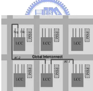
The regular distributed register (RDR) microarchitecture was proposed in [13]. It divides the entire chip into an array of islands which contains a local computational cluster (LCC), local storages and an FSM (i.e., a local controller), as shown in Fig. 4. Due to the highly regular layout, it is capable of providing accurate delay estimation for inter-island communication in early design phases.
The corresponding synthesis system called architectural synthesis for multicycle communication (MCAS) was also proposed in [13]. MCAS integrates global placement with scheduling and binding to effectively utilize the underlying architecture. The related studies focusing on behavior synthesis as well as scheduling and routing of global transfers can be found in [14]–[18].
2.3 Distributed Register-File Microarchitecture
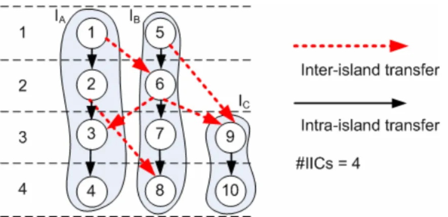
The island structure of DRFM is shown in Fig. 2. An island is composed of FUs, a local register file and input routing logic. The local register file is used to store computation results produced by internal FUs, and is responsible for feeding data to internal FUs and external FUs in other islands. DRFM allows use of the platform-featured on-chip memory or register-file IP blocks to implement its local register files, and this results in substantial saving of multiplexing logic and global interconnects [9].
The number of IICs on DRFM is used as the metric for QoR in early design phases because it is highly correlated with the area and performance of designs after synthesized [9]. Given a DFG, the required number of IICs can be identified after scheduling and binding, as shown in Fig. 5. The operations in the same shaded region are bound to the same island, and the ones in the same row are scheduled at the same cstep. Then, data transfers whose start node and end node are on different islands become inter-island transfers (IITs). Since DRFM assumes point-to-point IICs, two IITs can share an IIC, if and only if they are produced from a common island and consumed in another common island at different csteps [9]. In the example of Fig. 5, IIT1,6 and IIT2,8 can share an IIC between island A and island B, whereas
IIT5,9 and IIT6,9 must use two different IICs between island B and island C because they are
consumed at the same cstep.
An approach for IIC minimization on DRFM was also proposed in [9]. However, it takes scheduled DFGs as inputs and does not touch the scheduling during the synthesis process. This unavoidably loses some opportunities for optimization. [10] recognizes this issue, so it minimizes the cost of interconnections first to fully exploit the effects of scheduling on interconnect and then to schedule the operations later [10]. Although [10] takes the effects of scheduling into account, it models the problem as a timing-constrained one. As a result, [10] and our work are not comparable because it does not minimize the latency of DFGs whereas our work does.
[10] also points out the other issue about read port limitation of register files. [9] assumes that the number of read ports of register files is unlimited, but in practice, the number of read ports is usually limited because it directly affects the cost of register files. [10] deals with the access conflict of read ports by data forwarding only if it occurs after scheduling and binding. Unlike the approach in [10], our work combines the limitation of read ports with scheduling and binding to avoid the conflict increasing the latency of DFGs.
For simplicity, [9] assumes: (i) every operation can be executed in any island in one cstep and produces exactly one result; (ii) a local register file has only one write port for the writeback of FUs on the same island. We also take these two assumptions in our work.
2.4 Motivational Examples
2.4.1 Effects of Scheduling
As mentioned above, scheduling may limit the solution space. Given a scheduled DFG as shown in Fig. 6(a) and the resource constraint of two islands, the best result one can get through binding is presented in Fig. 6(b). The number of IICs in the example of Fig. 6(b) is two. If rescheduling is allowed during binding, a better solution than the one in Fig. 6(b) can be reached as shown in Fig. 6(c), where the number of IICs is one.
Note that the required numbers of csteps in two solutions are both minimized. That means the IIC reduction by rescheduling is not a tradeoff with the latency of DFGs.
2.4.2 Data Detouring
Data detouring can further decrease the number of IICs. Special nodes called bubbles are inserted into the DFG representing the idle csteps of islands explicitly, as shown in Fig. 7(a). The bubbles can be used as intermediate stops to detour IITs, as shown in Fig. 7(b). The intra-island transfers in Fig. 7(a) and (b) are not shown for simplicity. The number of IICs in the example in Fig. 7(a) is three while the number of IICs in the example of Fig. 7(b) is two.
Fig. 6(a): The scheduled DFG,
(b): the scheduled and bound DFG, and (c): the rescheduled and bound DFG.
2.4.3 Read Port Limitation
Incorporating consideration of read port limitation into scheduling and binding can avoid the increase of DFG latency due to access conflict of read ports. A scheduled and bound DFG, as shown in Fig. 8(a), is given without the consideration of the number of read ports during the process of scheduling and binding. Assume that each local register file has only two read ports. Access conflict of read ports would occur at cstep 4 because three variables, produced by v1, v2 and v3 are read from island A but the register file has only two read ports. One read
access of v4, v7 or v11 has to be postponed which consequently increases the latency of the
DFG to five. However, the access conflict can be avoided if the read port limitation is taken into account during the process of scheduling and binding, as shown in Fig. 8(b), where v6
and v7 are scheduled at cstep 4 and cstep 3 respectively.
The two solutions in Fig. 8(a) and (b) have the same number of IICs. Consequently, the access conflict can be avoided while maintaining the minimized number of IICs.
Fig. 7(a): The schedule and bound DFG with bubbles and
Fig. 8(a): A scheduled and bound DFG and
Chapter 3
Proposed Algorithm
3.1 Overview
The problem formulation of this work is as follows: Given a DFG and a resource
constraint (the number of islands), obtain a scheduled and bound DFG with the minimized latency as well as minimize the number of required IICs.
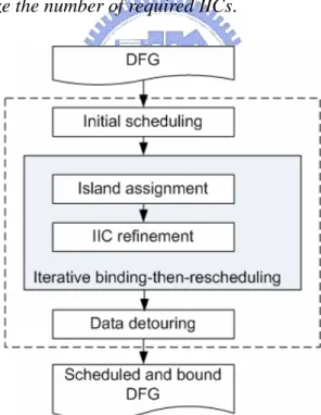
The overall flow of the proposed method is shown in Fig. 9. Given a DFG, list scheduling is first performed to obtain an initial scheduling result and followed by the iterative cstep-by-cstep binding-then-rescheduling process. In each iteration, two procedures, island
assignment (binding) and IIC refinement (rescheduling and rebinding), are applied
consecutively. The way used for island assignment in this work is similar to the horizontal
assignment adopted in [9]. Namely, island assignment is formulated as a minimum-weighted bipartite matching problem, where a weight on an edge represents the number of extra IICs
induced by the corresponding matching. However, the foregoing algorithm does not allow rescheduling and generally produces a locally optimized solution. Hence, an IIC refinement process is proposed to look for a better result from the expanded solution space via rescheduling. More details are described in Section 3.2. After the iterative phase, data detouring is then conducted and responsible for further IIC reduction. The related details are given in Section 3.3. In Section 3.2 and 3.3, the number of read ports of register files is unlimited, and then Section 3.4 explains how to integrate the consideration of read port limitation into the flow. In the end, a scheduled and bound DFG with minimized IICs is derived.
3.2 IIC Refinement
As mentioned above, the algorithm for island assignment generally leads to a locally optimized solution. However, further improvement can still be achieved by allowing certain operation rescheduling and rebinding, as depicted in Fig. 6(b) and Fig. 6(c), as long as the data dependency is still intact.
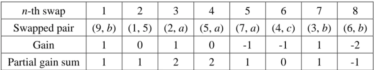
The proposed IIC refinement process is based on KL algorithm [23], which is broadly used in partitioning-related problem. Within the process, nodes and bubbles are swapped for IIC minimization. A swap can be made between two nodes or between a node and a bubble. A swap is considered feasible only on two conditions: (i) nodes must be unlocked, and (ii) data dependency must be preserved after swapping. For example, in Fig. 10(a), the feasible swap candidates for node 5 are {node 1, node 7, node a}. A feasible swap pair of node u and node/bubble v is denoted as (u, v). The gain of a swap pair is defined as how many IICs it can reduce, i.e., the difference between the numbers of IICs before and after the swap. The gain of a swap pair (u, v) is denoted as gu,v. All feasible swap pairs are collected into the feasible swap
pair set (FSPS). After performing an actual swap, FSPS and gains of swap pairs are updated accordingly. The key steps of IIC refinement are described as follows:
(i) Set all operation nodes unlocked.
(ii) Find a swap pair with the largest gain from FSPS. (iii) Swap the pair then lock the operation node.
(iv) Update FSPS and recalculate the gains of pairs in FSPS. (v) Repeat (ii) to (iv) until FSPS is empty.
(vi) Keep the fist k swaps and undo the rest if the partial gain sum of the first k swaps is the largest and positive; go to (i).
For example, a partially scheduled and bound DFG is shown in Fig. 10(a) with an IIC number equal to 4. Initially, the gains of all feasible swap pairs in FSPS are calculated as follows:
Then the swap pair (9, b) is selected to be swapped and node 9 is locked after the swap. This process is not terminated until FSPS is empty. Table 1 shows the gain and the partial gain sum of the eight consecutive feasible swaps in this iteration. As a result, only the first three swaps, including (9, b), (1, 5) and (2, a), are actually desired. The resultant DFG at the end of this iteration is shown in Fig. 10(b) and it merely requires 2 IICs instead of 4 in Fig. 10(a).
Fig. 10(a): The DFG at the beginning of the iteration and
(b): the DFG at the end of the iteration.
g1,5 = 0 g1,7 = –1 g2,a = –1 g2,8 = –1 g3,6 = 0
g3,9 = –2 g4,b = 0 g4,c = –1 g5,7 = –2 g5,a = 0
Table 1: Gains and partial gain sums in an iteration
n-th swap 1 2 3 4 5 6 7 8
Swapped pair (9, b) (1, 5) (2, a) (5, a) (7, a) (4, c) (3, b) (6, b)
Gain 1 0 1 0 -1 -1 1 -2
3.3 Data Detouring
As shown in Fig. 7 previously, data detouring can further reduce the number of IICs. However, not all the IITs can be detoured. Only the IIT with slack greater than zero, named
splittable IIT, can be detoured. The slack of an IIT is defined as (1), where T(vi) is the cstep in
which vi is scheduled.
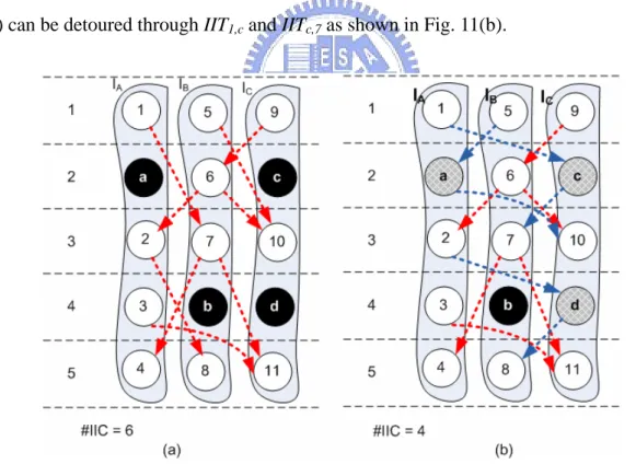
On the contrary, an IIT with zero slack is called a non-splittable IIT. As shown in Fig. 11(a), IIT1,7 and IIT2,8 are splittable, while IIT6,2 and IIT3,11 are non-splittable. For a splittable
IIT, it is possible to detour the transfer through a series of bubbles. For instance, IIT1,7 in Fig.
11(a) can be detoured through IIT1,c and IITc,7 as shown in Fig. 11(b).
Fig. 12 outlines the data detouring procedure. Since a non-splittable IIT cannot be detoured, an IIC is surely demanded for it. Hence, the objective for data detouring is to
1 2 2 1
( , ) ( ) ( ) 1
slack v v =T v −T v − (1)
Fig. 11(a): The splittable and non-splittable IITs, and
reroute certain splittable IITs so that the number of IICs can be further minimized. However, there can be no IIC reduction even after an IIT is successfully detoured. As discussed previously, the reason is that an IIC can be shared by several IITs, and it cannot be safely removed unless all the IITs utilizing it are successfully detoured. Therefore, to eliminate an IIC, all IITs utilizing it should be identified first, as indicated in Fig. 12.
Fig. 13 gives a heuristic-based policy to determine which IIC an IIT actually utilizes. If there are multiple IICs, this mapping strategy tries to assign fewer IITs with larger slack to latter IICs. It is because that an IIC is more likely removed when fewer IITs utilize it or those IITs are with larger slack. As shown in Fig. 11(a), nine IITs are mapped onto six IICs. For example, IIC1B,C contains IIT6,10 and IIT7,11, and IIC
2
B,C contains IIT5,10, where IIC 1
A,B denotes
the i-th inter-island connection between island IA and IB. After mapping all the IITs onto IICs,
two kinds of IICs are identified – the one containing at least one non-splittable IIT is a hard IIC; the other containing no non-splittable IIT is a soft IIC. As the above example, IIC1B,C is a
hard IIC because IIT6,10 is non-splittable, while IIC 2
B,C is a soft IIC since it only contains a
splittable IIT5,10. It is impossible to remove a hard IIC via data detouring due to non-splittable
IITs. On the contrary, a soft IIC can be eliminated if all the IITs utilizing it are successfully detoured. For example, there are two soft IICs in Fig. 11(a) – IIC1A,B can be removed if IIT1,7
and IIT2,8 can both be detoured, as well as IIC 2
B,C can be removed if IIT5,10 can be detoured. In
addition, an IIC is fixed if it is inherently a hard IIC or a soft IIC with at least one IIT which cannot be detoured.
An iterative edge splitting (i.e., IIT detouring) procedure is proposed to eliminate soft IICs as shown in Fig. 14. Bubbles are used while performing IIT detouring as mentioned previously. Since the number of bubbles is a constant, the fewer bubbles the current IIT consumes, the more bubbles the latter IITs can use for detouring. Furthermore, some bubbles can be used to detour many IITs while others can only be used by few IITs. For example, in Fig. 11(a), bubble c can be used to detour IIT1,7 or IIT5,10, but bubble a can only be used by
IIT5,10. Hence, the overall objective of the proposed iterative edge splitting procedure is to
detour a given IIC by using as fewer and less popular bubbles as possible. First, the detouring
graph for each IIT belonging to some soft IIC is created. It enumerates all possible detouring
paths via the existing fixed IICs. The detouring graphs of the example in Fig. 11(a) are shown in Fig. 15(a), 15(b) and 15(c). A weight is associated with a node and an edge to indicate its
importance and popularity.
For every source-destination island pair (IA, IB):
Sort all IITs (vi, vj), where vi ∈ IA and vj ∈ IB, in:
(i) Increasing order of T(vj) as the primary key, and
(ii) Decreasing order of T(vi) as the secondary key.
Map IITs onto IICs in the order generated above: (i) Attempt mapping an IIT onto the first IIC.
(ii) Attempt mapping an IIT onto the second IIC only when the first one is occupied, and so on so forth.
The weight of a source node of an IIT is defined as (2) to reflect its importance. Then weights of other nodes and edges are computed in topological order by (3) and (4).
Fig. 14: The iterative edge splitting procedure.
The bubble weights are therefore obtained by summing up weights in all detouring graphs. As the example in Fig. 15, the weights of node a, b, c and d are 0.5, 0, 1, and 0.5, respectively. After all bubble weights are available, the path with minimum-bubble-weight is identified then used to detour the given IIT. The minimum-bubble-weight problem can be formulated as the shortest path problem then solved accordingly. Once the given IIT is detoured, certain detouring graphs should be updated since some bubbles have already been consumed and are not available anymore. Since the fewer IITs a soft IIC contains, the more easily it can be detoured – the soft IICs containing fewer IITs would be processed earlier. For example,
IIC2B,C is processed before IIC1A,B.
Overall, the proposed procedure described in Fig. 14 attempts to detour IITs related to the target soft IIC in increasing order of their slacks. If there is one IIT which cannot be split, all previously-split IITs are recovered and the target IIC is therefore marked as a fixed IIC. On the contrary, if all IITs in the target IIC are successfully split, it can then be safely removed. In either case, the proposed procedure proceeds to the next candidate soft IIC. Note that the data detouring procedure never increases the number of IICs. The worst-case scenario which can be anticipated is that all soft IICs become fixed IICs and no IIC reduction is achieved. One last thing, the resultant DFG after data detouring is shown in Fig. 11(b), where the number of IICs is reduced from 6 to 4.
1 weight of a source node =
number of edges this IIC contains (2)
, weight of weight of = out-degree of i i j i v edge v (3)
(
,)
weight of = j weight of i j i v∑
edge (4)3.4 Extension for Read Port Limitation
As shown in Fig. 8, combining the read port limitation with scheduling and binding can avoid the access conflicts. This section gives an extended algorithm that takes the read port limitation into account.
In IIC Refinement, a secondary gain of swaps, defined as the decreased number of access conflicts of all islands at all csteps, is added. The number of access conflicts of an island at a cstep is calculated by demanded variables on that island at the cstep minus the number of read ports that a register file has. In Fig. 8, for example, the secondary gain of (6, 7) is one because there is a conflict (three demanded variables minus two read ports) at cstep 4 on island A before the swap (i.e., Fig. 8(a)), but there is no conflict after the swap (i.e., Fig. 8(b)). Meanwhile, the original gain (i.e., the reduced number of IICs) is called the primary gain.
The second step of IIC refinement is modified as follows: find a swap pair with the largest primary gain from FSPS; if there are many pairs with the same largest primary gain, choose the pair with the largest secondary gain. By means of secondary gain, read port limitation is well complied during scheduling and binding, so the access conflicts can be minimized.
In Data Detouring, only the paths which would not produce any access conflicts of read ports are considered while building detouring graphs. As a result, Data Detouring does not inject any access conflicts.
Chapter 4
Experimental Results
The proposed algorithm is implemented in C++/Linux environment, and all experiments are conducted on a workstation with an Intel Xeon 3.2GHz CPU and 4GB RAM. The test cases are from different benchmark sets [24]–[26], which are frequently used in the high-level synthesis field. The basic information of these test cases (DFGs) is shown in Table 2. The first three columns are the names, number of nodes and number of edges of the DFGs respectively, and the last one is the latency obtained by ASAP scheduling with unlimited resources. For fair and comprehensive comparison, two different synthesis flows are presented, as shown in Fig. 16. Given an input DFG and a resource constraint, list scheduling is first performed to provide an initial scheduling result for both flows. Flow1 implements the approach proposed in [9];
Flow2 applies the algorithm proposed in this work.
Two configurations are considered in our experiments – synthesis is performed without/with a resource constraint in Configuration 1/2, respectively. In the first configuration, the number of islands is set as the minimum number that still guarantees the synthesis outcome with the minimum latency indicated in Table 2. In Configuration 2, the number of islands is reduced by half as:
The results of the configuration 1 and 2 are shown in Table 3 and Table 4 respectively. The
numbers of islands in Config. 1 numbers of islands in Config. 2 =
2
⎢ ⎥
⎢ ⎥
second column is the number of the given island, and the third one is the latency of DFGs after list scheduling is applied; the fourth and fifth ones are the number of IICs by Flow1 and Flow2 respectively, and the sixth one is the percentage of reduction in terms of the number of IICs.
The experimental results of [9] showed that [9] was able to produce good solutions, but there is still room for improvement. The proposed algorithm can reduce the number of IICs on average by 21.1% without resource constraints (i.e., configuration 1). When the resource constraints (i.e., configuration 2) are applied, the results show that the number of IICs can still be reduced by 24.5% on average. Furthermore, the number of nodes of DFGs ranges from 40 up to 500, so the proposed algorithm remains consistent in the size of DFGs and the number of islands.
Moreover, the number of read ports is unlimited in the above experiments. Thus another experiment is conducted under read port number limitation, as shown in Fig. 17. A post-processing is added to remove the access conflicts. When access conflicts occur at a cstep, the operation with the smallest ALAP value is postponed one cstep, and the scheduling has to be modified to maintain data dependency.
The experiments are also conducted in the two different configurations, respectively. The results are shown in Table 4 and 5. The third column is the latency of DFGs after list scheduling, and the fourth and fifth ones are the latency by Flow3 and Flow4 after the post-processing; the sixth and seventh ones are the number of IICs by Flow3and Flow4.
The number of csteps of Flow3 increases by 12% on average because of the access conflicts, whereas that of Flow4 remains the same because the proposed algorithm integrates the read port limitation into scheduling and binding. The percentage of IIC reduction of Flow4 remains consistent, so the IIC reduction is not a tradeoff with the consideration of read port limitation.
art both with/without read port limitation. We believe that the advantage comes from the joint effects of the iterative binding-then-rescheduling scheme, the data-detouring process utilizing bubbles and the consideration of read port conflict.
Table 2: The basic information of benchmarks
Test case #nodes #edges ASAP latency
fir2 40 39 11 fir1 44 43 11 lee 49 62 9 cosine 82 91 8 honda 105 104 15 wribmp 106 88 7 dir 127 126 15 chem 342 327 15 fft16 414 672 14 u5ml 564 557 26
Fig. 16: Experimental flows w/o read port limitation.
Table 3: Experimental results of configuration 1 (w/o read port limitation).
#IICs
Test case #islands #csteps
Flow1 (1) Flow2 (2) Reduction (2 to 1) fir2 5 11 7 5 28.6% fir1 6 11 8 7 12.5% lee 6 9 11 10 9.1% cosine 12 8 27 24 11.1% honda 10 15 17 14 17.6% wribmp 16 7 18 14 22.2% dir 11 15 24 17 29.2% chem 24 15 61 38 37.7% fft16 32 14 204 178 12.7% u5ml 29 26 102 71 30.4% Avg. 21.1%
Table 4: Experimental results of configuration 2 (w/o read port limitation).
#IICs
Test case #islands #csteps
Flow1 (3) Flow2 (4) Reduction (4 to 3) fir2 2 21 2 1 50.0% fir1 3 17 4 3 25.0% lee 3 18 6 5 16.7% cosine 6 16 14 12 14.3% honda 5 23 9 8 11.1% wribmp 8 14 14 10 28.6% dir 5 27 11 8 27.3% chem 12 29 41 28 31.7% fft16 16 27 97 83 14.4% u5ml 14 42 55 41 25.5% Avg. 24.5%
Table 5: Experimental results of configuration 3, #read_ports = 2.
#csteps #IICs Test case #islands
LS (5) Flow3 (6) Flow4 Flow3 (7) Flow4 (8)
cstep_inc (6 to 5) IIC_red (8 to 7) fir2 5 11 11 11 7 5 0.0% 28.6% fir1 6 11 12 11 8 7 9.1% 12.5% lee 6 9 12 9 11 10 33.3% 9.1% cosine 12 8 9 8 27 24 12.5% 11.1% honda 10 15 16 15 17 13 6.7% 23.5% wribmp 16 7 8 7 18 12 14.3% 33.3% dir 11 15 16 15 24 18 6.7% 25.0% chem 24 15 18 15 61 43 20.0% 29.5% fft16 32 14 16 14 204 182 14.3% 10.8% u5ml 29 26 27 26 102 69 3.8% 32.4% Avg. 12.1% 21.6%
Table 6: Experimental results of configuration 4, #read_ports = 2.
#csteps #IICs Test case #islands
LS (9) Flow3 (10) Flow4 Flow3 (11) Flow4 (12)
cstep_inc (10 to 9) IIC_red (12 to 11) fir2 2 21 21 21 2 1 0.0% 50.0% fir1 3 17 17 17 4 3 0.0% 25.0% lee 3 18 22 18 6 5 22.2% 16.7% cosine 6 16 17 16 14 12 6.3% 14.3% honda 5 23 25 23 9 8 8.7% 11.1% wribmp 8 14 15 14 14 10 7.1% 28.6% dir 5 27 29 27 11 8 7.4% 27.3% chem 12 29 33 29 41 26 13.8% 36.6% fft16 16 27 41 27 97 84 51.9% 13.4% u5ml 14 42 46 42 55 42 9.5% 23.6% Avg. 12.7% 24.7%
Chapter 5
Conclusion
The number of IICs on DRFM is used as the metric for QoR in early design phases because it is highly correlated with the area and performance of designs. In this work, we have proposed a two-phase resource-constrained synthesis algorithm for IIC minimization targeting DRFM. The iterative binding-then-rescheduling procedure is first performed. Island Assignment maps operations onto islands, and a better result can be derived because the solution space is expanded by IIC Refinement. Moreover, the read port limitation is also considered in this work. Next, data detouring is applied for further elimination of IICs. The experimental results indicate that the proposed algorithm reduces the number of IICs by 24% on average as compared to the prior art.
References
[1] International Technology Roadmap for Semiconductors. Semiconductor Industry Association, 2005.
[2] D. Matzke, “Will physical scalability sabotage performance gains?” IEEE Computer, vol.20, pp. 37–39, 1997.
[3] L. P. Carloni and A. L. Sangiovanni-Vincentelli, “Coping with latency in SOC design,” IEEE Micro, vol. 22, pp. 24–35, 2002.
[4] N. Magen, A. Kolodny, U. Weiser, and N. Shamir, “Interconnect-power dissipation in a microprocessor,” Proc. Int’l Workshop System Level Interconnect Prediction, pp. 7–13, 2004.
[5] A. Singh, G. Parthasarathy, and M. Marek-Sadowska, “Efficient circuit clustering for area and power reduction in FPGAs,” ACM Trans. Design Automation of Electronics Systems, vol. 7, no. 4, pp. 643–663, Oct. 2002.
[6] E. Kusse and J. Rabaey, “Low-energy embedded FPGA structures,” Proc. Int’l Symp. Low Power Electronics and Design, pp. 155–160, 1998.
[7] D. M. Chapiro, “Globally-asynchronous locally-synchronous systems,” Ph.D. dissertation, Stanford Univ., Stanford, CA, 1984.
[8] L. P. Carloni, K. L. McMillan, A. Saldanha, and A. L. Sangiovanni-Vincentelli, “A methodology for correct-by-construction latency insensitive design,” Proc. Int’l Conf. Computer Aided Design, pp. 309–315, 1999.
[9] J. Cong, Y. Fan, and W. Jiang, “Platform-based resource binding using a distributed register-file microarchitecture,” Proc. Int’l Conf. Computer Aided Design, pp. 709–715,
2006.
[10] K. Lim, Y. Kim, and T. Kim, “Interconnect and communication synthesis for distributed register-file microarchitecture,” Proc. Design Automation Conf., pp. 765–770, 2007. [11] D. Kim, J. Jung, S. Lee, J. Jeon, and K. Choi, “Behavior-to-placed RTL synthesis with
performance-driven placement,” Proc. Int’l Conf. Computer Aided Design, pp. 320–325, 2001.
[12] J. Jeon, D. Kim, D. Shin, and K. Choi, “High-level synthesis under multi-cycle interconnect delay,” Proc. Asia South Pacific Design Automation Conf., pp. 662–667, 2001.
[13] J. Cong, Y. Fan, G. Han, X. Yang, and Z. Zhang, “Architecture and synthesis for on-chip multicycle communication,” IEEE Trans. Computer-Aided Design Integrated Circuits and Systems, vol. 23, no. 4, pp. 550–564, Apr. 2004.
[14] C.-I Chen and J.-D. Huang, “CriAS: A performance-driven criticality-aware synthesis flow for on-chip multicycle communication architecture,” Proc. Asia and South Pacific Design Automation Conf., pp. 67–72, Jan. 2009.
[15] S.-H. Huang, C.-H. Chiang, and C.-H. Cheng, “Three-dimension scheduling under multi-cycle interconnect communications,” IEICE Electronics Express, vol. 2, no. 4 pp.108–114, Feb. 2005.
[16] J. Cong, Y. Fan, and Z. Zhang, “Architecture-level synthesis for automatic interconnect pipelining,” Proc. Design Automation Conf., pp. 602–607, 2004.
[17] W.-S. Huang, Y.-R. Hong, J.-D. Huang, and Y.-S. Huang, “A multicycle communication architecture and synthesis flow for global interconnect resource sharing,” Proc. Asia and South Pacific Design Automation Conf., pp. 16–21, 2008.
[18] Y.-J. Hong, Y.-S. Huang, and J.-D. Huang, “Simultaneous data transfer routing and scheduling for interconnect minimization in multicycle communication architecture,” Proc. Asia and South Pacific Design Automation Conf., pp. 19–24, Jan. 2009.
[19] A. Ohchi, N. Togawa, M. Yanagisawa, and T. Hothuki, “High-level synthesis algorithms with floorplanning for distributed/shared-register architectures,” Proc. Int’l Symp. VLSI Design, Automation and Test, pp. 164–167, 2008.
[20] S. Gao, K. Seto, S. Komatsu, and M. Fujita, "Pipeline scheduling for array based reconfigurable architectures considering interconnect delays," Proc. Int’l Conf. Field-Programmable Technology, pp. 137–144, Dec. 2005.
[21] Altera website. [Online]. Available: http://www.altera.com [22] Xilinx website. [Online]. Available: http://www.xilinx.com
[23] B. Kernighan and S. Lin, “An efficient heuristic procedure for partitioning graphs,” Bell System Technical Journal, pp. 291–307, Feb. 1970.
[24] MCAS: multicycle architectural synthesis system. [Online]. Available: http://cadlab.cs.ucla.edu/software_release/mcas/
[25] ExPRESS group. [Online]. Available: http://express.ece.ucsb.edu/
[26] T. Cormen, C. Leiserson, R. Rivest, and C. Stein, Introduction to algorithms, 2nd edition, the MIT press, 2001.
[27] D. Herrmann and R. Ernst, “Improved interconnect sharing by identity operation insertion,” Proc. IEEE/ACM Int’l Conf. Computer Aided Design, pp. 489–493, 1999. [28] M. Potkonjak and S. Dey, “Optimizing resource utilization and testability using hot
potato techniques,” Proc. Design Automation Conf., pp. 201–205, 1994.
[29] C.-I Chen, Y.-T. Lin, W.-L. Hsu, and J.-D. Huang, "Communication synthesis for interconnect minimization targeting distributed register-file microarchitecture," Proc. Electronic Technology Symposium, Jun. 2009.