On the Design of Optical Buffer for Optical Input-Queued Switches
with Quality of Service Guarantees
Chun-Yuan Lin and Chien Chen
Department of Computer & Information Science, National Chiao Tung University
1001 TA HSUEH ROAD, HSINCHU 30050, TAIWAN, ROC
cylin@cis.nctu.edu.tw
and
cchen@cis.nctu.edu.tw
ABSTRACT
This paper presents a quality of service (QoS) enable optical delay line (ODL) architecture to solve the problem of resource contention and support multilevel priority queues in an optical packet switch. ODL has been used in optical packet switches to resolve resource contention; however, the packets travel continuously in ODL limits the management of random access of the packets and increases the packet loss probability. Moreover, multiple ODL sets usually are needed to realize multiple priority queues in order to support QoS. In this paper, a new Unicast Recirculatiion ODL (URODL) architecture is proposed to resolve the output contention problem in an input-queued optical packet switch. To improve relatively poor throughput due to the head of Line (HOL) blocking in the input-queued switch, we modify URODL to support a more efficient window-based lookahead scheduling algorithm. Furthermore, a control strategy is designed to turn a single set of URODL into multiple logical queues to hold different priority packets. The simulation results show our URODL model reduces packet loss effectively with the capability to support QoS. This URODL model can be easily implemented and managed in a fast optical packet switch.
Keywords: optical delay line, optical buffers, optical switch, quality of service, resource contention. 1. INTRODUCTION
With advancement of optical device technologies, photonic packet switching is emerged as a promising technology to provide very large switching capacity [1] [2]. Packet switches based on photonics have a few advantages over their electronic counterparts. An advantage is the optical transparency. Transparency means that, except for the packet header, the packet payload can be encoded in arbitrary format with arbitrary bit rate. In addition, the optical packet switches are considered an offered solution for the future broadband packet networks in term of cost, power consumption, and footprint size.
One issue in the implementation of optical packet switching systems is the lack of optical random access memory (RAM). In every switch, resource contention is an unavoidable problem, which degrades overall switch performance. The contention problem refers to the fact that more than one packet is destined to the same output port of the switching unit in the same scheduling time slot. When contention occurs, the control unit selects one of the contending packets and the switching unit switches it to its output port. The others packets, that lose contention, are buffered for scheduling in the next time slot. Unfortunately optical RAM suitable for buffering photonic packets has not yet been found. Instead of converting optical signal to electronic format, the alternative way is to use optical delay lines to realize an optical buffer.
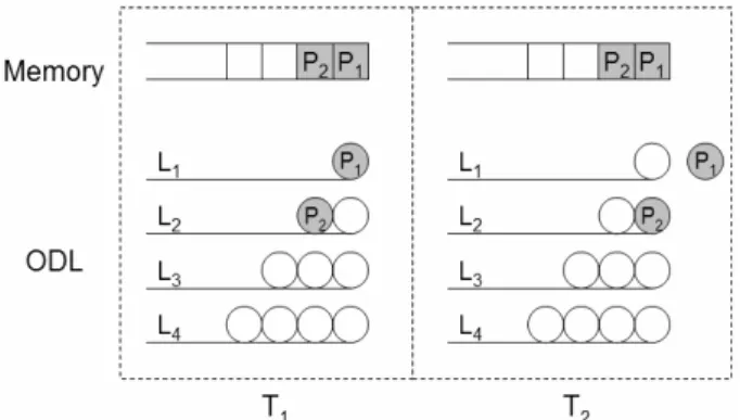
In general, optical delay line based buffer can be divided into two forms: traveling-type and recirculating-type as shown in Figure 1. A traveling-type buffer generally consists of multiple optical fiber delay lines whose lengths are equivalent to multiple of delay time unit T, where T is a basic period of light traveling a single delay loop. In such traveling-type buffer, the storage time of a packet is simply determined by the duration of a packet propagating through the length of optical fiber. Note that the number of delay lines increases as the buffer increases. Therefore, a large number of ODLs are needed to maintain a low packet loss rate. Furthermore, an optical packet is dropped due to the packet reaching the end of fix-length optical delayed line while its destine output port is not free. Figure 2 describes how a packet is dropped while it travels to the end of an ODL. At time slot T1 assume there are two packets in buffer, P1 and
P2. If contention happens at T2, P1 should remain in the buffer to wait for scheduling in T3. Unfortunately P1 leaves ODL
and is dropped because packet P1 reaches the end of ODL even when the ODL buffer is not full. Figure 1.b
one circulation time equal to delay time unit T. The storage time of a packet in such a recirculating-buffer is determined by the number of circulation multiplied by the delay time unit T. Both of above two buffers are able to store multiple packets with the constraint that only one packet enters and leaves the buffer at a time. The recirculating-type buffer is more flexible than the traveling-type buffer in that the packet storage time is adjustable by changing the number of circulating. The optical packets would not be dropped even through output contention is happening, since packets can be circulated back to the ODLs. The optical packets are only dropped while optical buffer is full. However, a significant problem with the recirculating-type buffer is that the signal has to be amplified during each circulation to compensate for the power loss. This results in accumulated spontaneous emission (ASE) noise [3] from the optical amplifier and severe signal-level fluctuation, which eventually limits the maximum number of recirculation.
Recently, the issue of supporting QoS guarantees in optical networks has become increasingly important [4] [5]. The switch mostly uses multiple priority queues to store packets of different priorities to manage QoS. It means that multiple sets of ODLs are needed to support multiple priority queues. However, ODL is much more expensive than electronic RAM. Besides, it remains a challenging design issue to provide multiple priority queues using a single set of ODL.
To resolve these problems, we propose a QoS enable ODL architecture, called unicast recirculation ODL (URODL) for the input-queued optical packet switch. The URODL architecture takes advantages of both traveling-type and recirculating-type buffer. It efficiently suppresses the packet loss probability from resource contention by redirecting packets back to optical delay lines with different delay lengths. Due to the recirculation capability, our URODL not only provides better random access and larger buffer size than traveling-type ODL for the same number of optical delay line. But also it significantly reduces the number of circulation comparing with recirculating-type ODL for the same delay requirement. This is because of, in URODL, multiple delay lengths instead of a single delay unit can be selected for more flexible delay combination to satisfy different delay requirements. To improve relatively poor throughput due to the head of Line (HOL) blocking in the input-queued switch, a window-based lookahead scheduling algorithm is implemented in URODL by selecting packets other than just the one at the head of the line. Furthermore, we extend the URODL to support QoS. A simple control strategy turns a single set of URODL into multilevel logical queues to hold different priority packets. The lengths of different priority queues are not fixed. The variable length priority queues in URODL are much more cost effectively than using multiple set of ODLs to support QoS.
This paper is organized as follows. In Section II, we describe the architecture of unicast recirculation ODL. The variant of URODL to support a window-based lookahead scheduling algorithm is proposed in section III. In Section IV, a detailed control strategy to turn URODL into multiple priority queues is given. It shows that the URODL is easy to support QoS. In Section V, some simulation results show the URODL indeed has better performance than traveling-type and recirculating-type ODL. In supporting QoS, the simulation results show the higher priority packets have excellent loss probability. By measuring the number of recirculation, we then can limit the maximum number of recirculation of each packet to prevent ASE noise. Finally we conclude the paper in Section VI.
2. UNICAST RECIRCULATION ODL ARCHITECTURE
In a conventional electronic switch, RAM is used as a buffer to store packets when contention occurs. However, in all optical packet switches, ODL rather than RAM is used to store packets in optical form without optical-electronic and electronic-optical conversion. Figure 3 is input-queued optical packet switch architecture. Packets can be stored in buffer (ODLs) for several time slots if the contention happens continuously.
[6]-[8] propose several cascaded optical delay line architectures using 2x2 switch in multi-stage construction. It allows redistributing packets contending for the same resource over time and space, while keeping them in optical form. Thus, rescheduling of resource access by the contending packets can be obtained. However, some extended problems such as packets travel continuously without recirculation and QoS support still occur when using multi-stage ODL.
Another optical buffer model called wavelength routing-based buffer, which consists of a set of delay lines sitting between two arrayed-waveguide gratings (AWGs), is proposed in [9]. The first AWG switches packets to different delay lines according to packets’ resident wavelengths. Note that all the delay time slots of each packet are disjoint because no more than one packet is switched to the same delay line. Therefore, wavelength routing-based buffer can be shared by all the switch input ports to act as a shared memory buffer. A wavelength routing-based buffer [9] with an added circulative loop which provides additional delay time is proposed in [10]. The AWG and erbium-doped fiber amplifier (EDFA) are also used in the loop. However, due to noise caused by EDFA, the number of packet recirculation time is still limited.
To eliminate the optical packets continuous propagating out of the optical delay line, recirculation ODL redirects the propagated packet back to the buffer to store optical data. Figure 4 shows three possible recirculation methods -
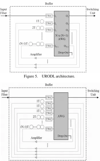
broadcast, multicast and unicast. In this case, broadcast RODL makes four, i.e. the buffer size, copies of propagating packet and redirect them back to all the delay lines. The redirected packet can wait for at most four time slots without being recirculated again. The control unit can select one of the four packets when it wins contention. This ability to select from four packets is useful when contention occurs continuously. Unfortunately, the RODL with broadcast may block incoming packet when contention occurs and the input packet arrivals simultaneously. Hence, the broadcast method is inefficient and the packet loss probability is still high. The second method multicast RODL in Fig. 4 makes just two (two is the number of packets in the ODLs) copies to prevent blocking incoming packet in broadcast RODL. However, control is not easy because the number of copies is not fixed and the buffer still contains too many copies of the same data. The third recirculation method, unicast RODL (URODL), which is preferred herein, only redirects the packet back to particular delay line without any additional copy’s being made. Not only does URODL excel in packet blocking performance, but also URODL can more easily be controlled than the other two recirculation methods. Figure 5 depicts the architecture of URODL. An Nx(N+1) (N is number of delay line) AWG and tunable wavelength converters (TWC) is used to switch optical packets to a certain delay line for buffering, pass-by, or drop-out. The optical amplifiers may be needed to compensate the insertion loss when light travels through AWG and ODL. To compare with a multi-stage delay line buffer [7]-[8], their control unit must control the entire 2x2 switches which cause noise and crosstalk. In general, fewer optical components not only reduce the cost of optical switches, but also imply better noise and crosstalk performance. However, URODL only needs to control TWCs to switch packets as required. The URODL is more easily implemented and more cost effective than the multi-stage delay line buffer as shown in Table 1. Table 1 indicates the control complexity and the amount of components in URODL and [7]-[8]. In Table 1 we only consider an optical buffer that has maximal delay B. time slots. The processing time of each scheduling is proportional to the control components. It includes the processing time to control all the optical components such as 2x2 switches, TWCs and AWG. In [7]-[8], the delay line architectures are organized as cascaded construction and the processing time is long due to the result that the control unit has to control each 2x2 switch. The first column “Control Operations” in Table 1 indicates that how many control operations a packet needs when it passes through the buffer. URODL only needs O(R) because a packet can be redirected back to delay line R times at most, where R is the maximal recirculation time. In [7]-[8] each packet needs O
(
log2B
+1)
and O(B+1) control operations respectively due to their cascaded architecture. The “totaldelay loops” in Table 1 indicates the number of total delay loops needed to support maximum delay B. In URODL the longest delay line only needs
B/
R
delay loops, since packets can be redirected back to the longest delay line R times to achieve maximum delay time B. When R=1 URODL works as a traveling-type buffer. The total delay loops of URODL is 2 1 2 1 + × = + + + R B R B R B L . (1) Therefore, if number of delay loops needed in URODL is concerned, we can increase number of recirculation R.3. WINDOW-BASED LOOKAHEAD URODL
Due to Header of Line (HOL) blocking in the input-queued optical packet switch architecture, the URODL can only achieve 58% of throughput theoretically [11]. When a HOL packet cannot be cleared because of its loss in output contention; it may block the packet behind, which may be destined for an idle output. This phenomenon is called HOL blocking. In order to increase throughput, the window-based lookahead scheduling is used to increase scheduling efficiency. That is, at the beginning of each time slot, the first w packets in each input queue sequentially contend for access to the switch output where w is the window size. Due to output conflict, some inputs may not be selected to transmit the HOL packets, and they send their second packet in line to contend for access to the remaining output that are not yet assigned to receive packets in this time slot. This contention process repeats up to w times in each time slot. The throughput is significantly improved on increasing the window size from 1 to .2, 3, and 4. However, the improvement saturates with large number of window size [12].
To improve switch performance, we propose a window-based lookahead URODL with window size w = 3 as shown in Fig. 6. Comparing with URODL, the window-based lookahead URODL with window size w = 3 adds only two more delay lines which can delay one time slot. The first three packets in a queue are put in the three one time slot delay lines sequentially. The packet in the first delay line contends for the output ports first. If the output contention happens to the packet in the first delay line, then the packet in the second delay line contends for the available output ports, and so on.
In the window-based lookahead URODL we prefer small window size, since the larger window size used, the more optical components needed and the longer scheduling time required. Nevertheless, the simulation result shows small window size can improve the switch performance effectively.
4. QoS SUPPORT IN URODL
Generally, a switch uses several queues of different priority levels to support QoS. URODL can support multiple priority queues in a single set of ODL. The lengths of different priority queues are not fixed. The variable length priority queues in URODL are much more cost effectively than using multiple set of ODLs to support QoS. Hence, URODL is an efficient component for temporal storage of multiply priority optical packets.
URODL is hereafter assumed to support three priority levels - high, medium and low. Figure 7 shows an example of URODL with three multilevel variable priority queues. Each packet has its own POS, which indicates the position of the packet in the queue. If a packet’s POS is 4, it is allocated to the fourth position from the head of the queue. When this packet enters AWG, it will be switched to O4 in Fig. 5 and is delayed for four time slots. PRIH, PRIM and PRIL are the
numbers of packet with high, medium and low priority respectively, and count specifies how many packets are in the URODL; it equals to the sum of PRIH, PRIM and PRIL. The following shows the details of our algorithm.
When an incoming packet enters this URODL, it is classified by priority and inserted into a certain position of the queue. If the packet priority is “high”, the packet will be inserted between the last high and the first medium priority packets of the queue, its POS is PRIH+1. If the priority is “medium”, it is inserted between the last medium and the first
low priority packets, and its POS is PRIH+PRIM+1. If the priority is “low”, it is inserted at the end of queue, and its POS
is PRIH+PRIM+PRIL+1. This algorithm ensures that no lower priority packet can be switched out before a higher priority
packet.
Figure 8 is an example shown in time slot by time slot. The control strategy works in each time slot as follows.
T1: Initially assume four packets in URODL: one is high priority, one is medium priority and the other two are low
priority. In this time slot, PRIH and PRIM are both one and PRIL is two.
T2: In this time slot, a high priority packet enters ODL; its POS is assigned as two because one high priority packet is
present in ODL, and then PRIH increases by one unit. POS of each medium and low priority packet increases by one,
since the incoming packet is inserted in front of these packets. Resource contention also occurs in this time slot, so H1 is
redirected back to delay line 1T to prevent losses.
T3: The resource contention occurs continuously. Packets located on the head of the delay line are redirected back into
1. count = 0;
2. if incoming packet enters and count < queue_size then
switch “incoming packet priority” case “High”:POSincoming= PRIH;
PRIH = PRIH + 1;
POS = POS + 1, for packet whose priority is “Mid” and “Low”;
case “Mid”: POSincoming = PRIH + PRIM;
PRIM = PRIM + 1;
POS = POS + 1, for packet whose priority is “Low”;
case “Low”: POSincoming = PRIH + PRIM + PRIL;
PRIL = PRIL + 1;
count = count + 1; 3. if no contention and count > 0 then
if PRIH > 0 then PRIH = PRIH – 1;
else if PRIM > 0 then PRIM = PRIM – 1;
else PRIL = PRIL – 1; count = count – 1;
POS = POS – 1, for all packets;
4. AWG destines an incoming packet (if exists) and packets at head of delay line to their corresponding output ports 5. jump 2.
the delay line according to their own POSs. Hence, H1 is switched to 1T to cause a delay of one more time slot and M1 is
switched to 3T. In fact, redirecting a packet back to URODL does NOT reorder the sequence of all the packets. Only a packet who’s POS is equal to zero can be switched to O0 as in Fig. 5 and can leave URODL. No packet can leave
URODL if some other packets exist whose POS is smaller.
T4: In this time slot, no incoming packet and no contention occur. POS of all packets decreases by one. H1 leaves ODL
because its POS is equal to zero, it is switched to O0 as in Fig. 5 and enters switching unit. H 2 and L 1 are redirected
back to ODL to wait for scheduling in the next time slot.
5. SIMULATION RESULTS
This section presents the simulation results concerning the packet loss probability and average recirculation time. We consider input-queued switch in evaluating the performance of URODL. Only the packets at the head of the queues (i.e. the packet who’s POS is zero) can content for their destined outputs. In window-base lookahead URODL, the first w packets in each input queue sequentially content for access to the switch outputs. In our simulation, packets arrive at each input port following Bernoulli process with different offered load. The destination of each incoming packet is uniform distributed. That is, for a given offered load ρ in an NxN switch, the packet arrives at each input port with probability ρ and each packet destines to a particular output port with probability 1/N. The multilevel priority URODL serves packets on a “straight priority” basis, i.e., if there exists a higher priority packet in multilevel priority URODL, and then no lower priority packets can be served. When multilevel priority URODL is full and an incoming packet whose priority is higher than one of the packets in URODL, the packet at end of URODL is dropped and the incoming packet is inserted to a position determined by the control algorithm detailed in section IV.
Figure 9 presents the simulation results of traveling-type ODL with and without recirculation in a 32x32 switch. Fig. 9.a and 9.b plot the distribution of packet loss probability with buffer sizes of 16 and 64 respectively. In Fig. 9, the gap between the two curves is caused by the packet traveling out of
ODL, while contention happens. The traveling-type ODL cannot hold the packets propagate out of ODL, but URODL can do so by recirculation. The simulation result shows URODL can reduce the packet loss probability significantly.
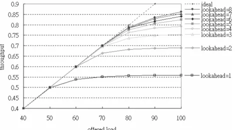
In Fig. 10, we show the simulation result for the proposed window-based lookahead URODL architecture with window size w increases from 1 to 8. Notice that when a window size w = 1 corresponds to the original URODL. The maximum throughput can be achieved are 0.56, 0.69, 0.75, 0.79, 0.82, 0.84, 0.85, and 0.86 respectively for various window size w = 1, 2, 3, 4, 5, 6, 7 and 8. The throughput improves significantly (about 23%) by increasing window size
w to 2. The window size of 4 improves the maximum throughput by about 5% compared with the window size of 3. As
shown in the simulation results, the improvement decreases to about 1%, as the window size increases from 6 to 7, and 7 to 8. Therefore, in order to reduce the HOL blocking people can choose the window-based lookahead URODL with window size of 2, 3 or 4 instead of large window size which needs more additional optical components and slower scheduling time.
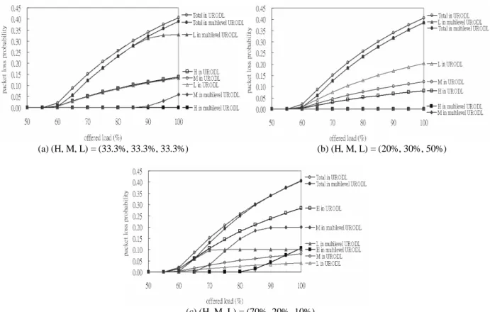
Figure 11 and Figure 12 depicts the simulation results of URODL with QoS support, and compares it to the URODL without QoS support, using a 32x32 switch and a buffer size of 16. In Fig. 11 the packet loss probability is computed by number of packet loss in each class divided by total number of incoming packet. In Fig. 12 the relative packet loss probability is computed by dividing the number of lost packets in each class by the total number of incoming packets in each class. Three priority levels, high, medium and low, are assumed. The URODL without QoS support serve packets without distinguishing the packet priority. The control strategy we proposed in this paper for the QoS enable URODL is used to simulate the packet loss probability among three priority levels. Three different combinations of incoming packet priority are used to observe the packet loss probability. In uniform priority distribution as shown in Fig 11.a, the low and medium priority packets of multilevel priority URODL inherit the packet loss probability of the high priority packets, so the loss probability of high priority packets almost reaches zero. Even in non-uniform priority distribution shown in Fig. 11.b and Fig. 11.c, the high priority packet loss probability is still close to zero. In Fig 11.c, the high priority packets take 70% of overall incoming packets, the high priority packet loss probability remains zero under 80% offered load. However, in URODL without QoS support, the loss probability associated with each priority level is proportional to the distribution of the incoming packet priority; the higher priority packet may be dropped even when the lower priority packet is in the queue. Fig 11.a shows the packet loss rates are same among high, medium and low priority packets while URODL without QoS support is used. Furthermore, in Fig 11.c and Fig 12.c, we can observe when the loss rate of high priority packets reaches zero under 80% traffic load, the loss rate of medium priority begins decreasing. It happens again when the loss rate of medium priority packet gets down to zero, the loss rate of low priority packets starts decreasing. The results show that the higher priority packets are given the preemptive authority to prevent
loss in multilevel priority URODL. In Fig. 11.c the packet loss probability of medium priority packets in multilevel priority URODL is higher than the low priority packets, this is because the medium priority packets take 20% of overall incoming packets and the low priority packets only take 10% of overall incoming packets. Figure 12 shows that the relative packet loss of each priority class. In Figure 12 we see more clearly about packet loss probability among three different priority classes. They show that the relative packet loss probability of higher priority packets is always less then the lower priority packets in multilevel priority URODL. However, in URODL without QoS support the relative packet loss probability among three priority classes are the same. This shows that our multilevel priority URODL can guarantee QoS by distinguishing packets among the three different priorities.
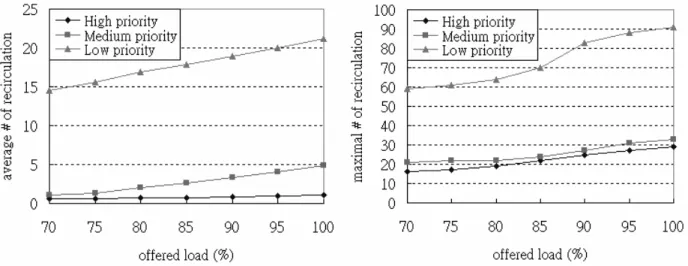
In simulating packet loss probability of URODL and multilevel priority URODL, statistics are also gathered on the average and maximal times of recirculation in multilevel priority URODL, as shown in Fig 13. Because of insertion loss appearing invariably in AWG and ODL, the times of recirculation while a packet is waiting for scheduling may cause the intensity of light to decline. An optical amplification can be used to URODL to boost the optical signal. However, ASE noise limits the number of times that a packet can travel through the optical amplifier. In URODL, the average times of recirculation in Fig 13.a indicate that the high and medium priority packets require only few recirculations on the average. The high priority packets experience average less than two recirculations. The maximal number of recirculations in Fig 13.b shows that in the worst case a low priority packet could be recirculated in a large number of times. Even though the lower priority packets may be dropped due to large number of recirculation, the optical signal integrity of higher priority packets can be guaranteed.
6. CONCLUSION
In this paper, we proposed a novel URODL architecture to reduce the high packet loss probability in ODL. Although several traveling-type fiber delay line buffer architectures have been previously proposed, none of them can keep the optical packets propagated at the end of delay line while they lose contention due to output conflict. Recirculation in URODL can redirect propagated packets back to the buffer to wait for scheduling in next time slot. All the packets can be stored in URODL without dropping packets except when the buffer is full. In order to improve input-queued switch performance, we develop a variant of URODL to alleviate head of line blocking by window-based lookahead selection. With URODL architecture proposed in this paper, multilevel priority queues with an efficient control strategy can be supported. Multilevel priority URODL supports multiple priority queues in a single optical delay line set. A flexible priority management scheme efficiently takes advantage of shared buffer space. It substantially reduces the packet loss probability by several orders of magnitude for high and medium priority packets when supporting QoS.
The simulation results show that URODL can reduce the packet loss probability, compared to conventional traveling-type ODL which cannot hold packets in the buffer continuously. The window-based lookahead URODL furthermore improves 20% of switch performance. While supporting QoS guarantees, multilevel priority URODL also provides negligible loss probability of high priority packets. Finally, the number of recirculation is investigated due to the concern of ASE noise from the optical amplifier in recirculating-type buffer. The simulation results show that average number of recirculation is less than two for the high priority packets. Therefore, URODL is much more practical than the conventional recirculating-type ODL in the implementation of optical switches.
ACKNOWGEMENTS
This research is supported by National Science Council under Grant Nos NSC-91-2218-E-009-016 and NSC-92-2213-E-009-068.
REFERENCES
1. F. Callegati, G. Corazza, C. Raffaelli, “Design of a WDM optical packet switch for IP traffic”, Proceedings of
IEEE GLOBECOM 2000, San Francisco, pp. 1283-1287, November 2000.
2. P. Green et al., “All-optical packet-switched metropolitan-area network proposal”, J. Lightwave Technol., Volume
11, pp. 754-763, May 1993.
3. A.Dickson and R.S. Tucker, “Noise accumulation in fiber loop memories”, in Proc.17th Australian Conf. Optic. Fiber Technol., postdeadline paper, pp.4, 1992.
networks”, IEEE Journal on Selected Areas in Communications, Volume: 18 Issue: 10, pp. 2062-2071, Oct 2000. 5. Callegati F., Corazza G., Raffaelli C., “Exploitation of DWDM for optical packet switching with quality of service
guarantees”, IEEE Journal on Selected Areas in Communications, Volume: 20 Issue: 1, pp. 190-201, Jan 2002. 6. Harai H., Wada N., Kubota F., Chujo W., “Contention resolution using multi-stage fiber delay line buffer in a
photonic packet switch”, IEEE International Conference on Communications, vol 5, pp. 2843-2847, May, 2002. 7. Hunter, D.K., et al., “2×2 buffered switch fabrics for traffic routing, merging, and shaping in photonic cell
networks”, Journal of Lightwave Technology, Volume: 15 Issue: 1, pp. 86-101, Jan 1997.
8. Cerisola, M., Chang-Jin Suh, et al., “CORD: contention resolution by delay lines”, Selected IEEE Journal on Areas in Communications, Volume: 14 Issue: 5, pp. 1014-1029, Jun 1996.
9. Wen De Zhong, Rodney S. Tucker, “A new wavelength-routed photonic packet buffer combining parallel delay lines with delay-line loops”, Journal of Lightwave Technology, Volume: 19 Issue: 8, pp. 1085-1092, Aug 2001. 10. Wen De Zhong, Rodney S. Tucker, “Wavelength routing-based photonic packet buffers and their applications in
photonic packet switching systems”, Journal of Lightwave Technology, Volume 16, No. 10, pp. 1737-1745, October 1998.
11. M.G. Hluchyj and M. J. Karol, “Queuing in high-performance packet switching”, IEEE JSAC, 6(9), pp.1587-1597, Dec. 1988.
12. H. Jonathan Chao, Cheuk H. Lam, Eiji Oki, “Broadband packet switching technologies”, John Wiley, New York, 2001.
(a) traveling-type buffer (b) recirculating-type buffer Figure 1. Schematic of photonic packet buffers based on optical delay lines.
Figure 2. Problem of packet continuous propagation in ODL.
Figure 3. Input-queued optical packet switch.
Figure 5. URODL architecture.
Figure 6. Window-based lookahead URODL with window size w=3.
Figure 7. Diagram of control strategy of URODL. count: number of packet in URODL; PRIH: number of high priority packets;
Figure 8. Example of packet allocation in URODL.
(a) buffer size = 16 (b) buffer size = 64
Figure 9. Simulation results concerning packet loss probability of 32-port input-queued switch with different buffer size.
(a) (H, M, L) = (33.3%, 33.3%, 33.3%) (b) (H, M, L) = (20%, 30%, 50%)
(c) (H, M, L) = (70%, 20%, 10%)
Figure 11. Simulation results of packet loss probability of 32-port input-queued switch with different distribution of packet priority.
(a) (H, M, L) = (33.3%, 33.3%, 33.3%) (b) (H, M, L) = (20%, 30%, 50%)
(c) (H, M, L) = (70%, 20%, 10%)
Number of
Proposed Optical Buffer
Control Operations 2x2 Switch AWG Total Delay Loops
URODL O
( )
R none 1 2 1 + × R B R B 2x2 Switched Bufferin [7] O
(
log2B
+1)
log2B
+1 none BCORD in [8]
O
(
B
+
1
)
B
+
1
none BTable 1. Control complexity and amounts of components in proposed optical buffer architectures. Assume that all these optical buffers can delay packets B time slots in maximal. R is the maximal recirculation time in URODL.
(a) average number of recirculation (b) maximal number of recirculation. Figure 13. Average and maximal times of recirculation of 32-port switch with buffer size 16.