ar
cture
for
AT
J .-M. TsaiC.-Y.
LeeIndexing terms: ATM system, ISDN, Quality of service, Scheduling
Abstract: A novel architecture and an enhanced approach to a flexible, starvation-free ATM QoS
managing function is proposed. To meet the stringent timing constraint of the delay QoSs, both high-speed sorter and subtractor are exploited to sort the priority value as well as to process the priority value. The subtractive policy is used to prevent starvation and to assign the priority of each output queue. In addition, to prevent underflow of priority value and to process the empty queue situation, both renormalisation circuit and empty flag are exploited to perform the normalisation function. Simulation results show that the throughput of the enhanced architecture is more than 50M output requests per second (21.2Gbith for ATM cells) by using a 1 . 2 p CMOS process. The proposed architecture can be cascadable, making it very suitable for complex QoS management.
1 Introduction
Broadband ISDN or B-ISDN will become one of the most important communication styles. By using an ATM technique, B-ISDN allows various applications to share a high-bandwidth transmission channel. One can predict that the applications on ATM networks will become more and more complex and the network system will provide more Quality of Services (QoSs) to satisfy those applications. Most of today’s ATM sys- tems [3-61 provide more than four QoSs. The input packets are usually classified into corresponding queues by their different delay and cell loss rate requirements. In some cases [6], more QoSs are provided by ATM systems to meet application needs. For example, multi- cast cells, best effort cells. and some OAM cells can be formed into individual QoSs to improve system effi- ciency.
The priority policy of an ATM system can be set by
two parameters, one is timing or delay, the other is
protection or cell loss rate. In a real ATM system, there is more time to process the priority policy on cell loss rate, because one can set the warning logic to detect the buffer utilisation. And when the monitor cir-
0 IEE, 1997
IEE Proceedings online no. 19971685
Paper fnst received 15th July 1996 and in revised form 25th April 1997
The authors are with the National Chiao Tung University, Department of
Electronics Engineering, 1001 University Road, Hsinchu, Taiwan, Republic of Chma
412
cuit indicates that the buffer will overflow, one can first drop the low-priority cells and use the back-pressure signals to inform input ports for ongoing services. In a real ATM system such a situation will not occur twice in only a few cell times, so there is a longer reaction time to deal with the cell loss rate priority. However, the processes of delay priority are more critical in an ATM system. Whenever the output port is ready and there are cells in output queues, the ATM switch con- troller must decide which nonempty queue can access the output port. If the output circuits are shared by many output ports like the architectures of most shared-buffer ATM switches, the output circuits only have several cycles to select one queue among all delay QoSs of a certain output port.
For this reason most ATM switches [3, 51 serve the highest priority ATM cells unless the highest priority queues are empty and then cells with lower priority can be served. The scheduling algorithm among delay QoSs
is static. Starvation occurs when continuing higher pri- ority cells arrive. To prevent starvation the scheduling algorithm can be modified by using the ageing tech- nique [8] to increase the priority of suspended cells per certain time period. To achieve the ageing function, one can modify the controller of ATM switch to proc- ess the lower delay priority ATM cell queues once per certain period. However, one can predict that there are more kinds of applications that will be provided by ATM networks resulting from the fact that the ATM system provides more different QoSs and schedules all the different QoSs to share network bandwidth. As
with the history of resource scheduling policies in com- puter systems, it will need a general-purpose, flexible, and powerful scheduling engine to solve all the schedul- ing problems.
Chao and Uzun [7] proposed an architecture based on a hardware sorter to provide a general-purpose scheduling function. By using a high-speed hardware sorter, this architecture can achieve a performance five times more than needed. Indeed, the architecture pro- vided by them is used to perform the scheduling func- tion for a single port, but seems to be an overkill. We propose a novel architecture based on a newly devel- oped high-speed sorter [l, 21 to provide a high-speed, flexible scheduling function to aid the QoS manage- ment of an ATM switch controller. By modifying the structure of the hardware insertion sorter, the proposed architecture can be shared by all output ports to enhance overall hardware efficiency.
2 Algorithm
In this Section we first present an algorithm to manage QoSs based on sorting concept. Then an example is
given to see how the proposed QoS manager works to solve the starvation problem. In addition, we discuss the key parameters needed in the algorithm.
2.7
00s
management approach based on
sorting concept
There are usually several output queues (for each QoS) per output port in real ATM switches, and some out- put ports may use the same set of output circuits to reduce hardware cost [3]. Indeed, the output circuits are shared by all output ports in most shared-buffer ATM switches. If there is a high-speed hardware sorter which can meet speed requirement, one can use only one set of priority process circuit, i.e. it can be shared by all output ports. The data flow diagram of the pro- posed QoS management approach is shown in Fig. 1.
cell input priority pool priority data of other queues in same port
r
-T
output candidate cell input priority processor to change priority valuenew priority value
Y
I
sortI
I I
I
new priority orders ofthis port
Fig. 1 Block diagram of proposed QoS management algorithm
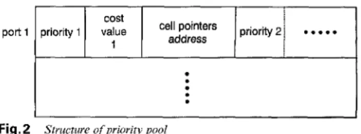
A priority pool can be used to store priority data of all ports. Each element of the priority data pool stores all QoS data for a certain port. Except the cell pointer and other related messages, each queue of a port needs a priority value and a cost to perform the scheduling function. The QoS data within the same entry are sorted by priority value.
As the output request arrives, the ATM cell queue with the highest priority will be sent to the output stage while the others will be sent into the sorter with their associated ranks. The priority data and cost of each output queue (supposing the larger priority value repre- sents higher priority) will be sent to the priority processing element to generate a new priority value.
The priority value of each output candidate is gener- ated by a priority processor using an old priority value and its corresponding cost. The new priority value is sent to the sorter to determine its new rank. After sort- ing, the queues of this port have been sorted based on priority value and written back to the priority pool until the next output request arrives. To further illus- trate the proposed scheduling algorithm, a C-like description is given in the Appendix (Section 9.1).
The structure of the priority pool is shown in Fig. 2. Each entry of the pool stores all queues and their cor- responding messages. The cost is used to control the
IEE Proc.-Commun., Vol. 144, No. 6, December 1997
accessed frequency of all queues. Because of the finite- word-length effect, it needs a renormalisation process to prevent underflow or overflow.
port 1
Fig.2
.
.
.
Structure of priority pool
By choosing a good cost function and appropriate cost values, a starvation-free and efficient scheduling policy can be realised.
2.2
ExampleBecause the substraction scheme is easy to implement and provides an ageing function inherently, the cost function is chosen for the priority processor in this example.
Each queue is assigned to a smaller cost value for a higher priority (higher access frequency) cell, because the small cost value implies a slow decay rate on prior- ity value. If we set all costs larger than 0, all priority values in the same port will decay continuously, so the queue with the lowest priority will become the output candidate after a certain time. Starvation can be pre- vented by setting all cost values larger than 0.
Because the priority value of each queue will be sub- tracted by a cost value that is equal to or larger than zero, the renormalisation function is required to pre- vent underflow of the stored priority values. Renormal- isation of the priority values is very simple in this example. When a new priority value is generated, the new value will be compared with the associated cost value. If the priority value is less than the correspond- ing cost value, the priority value of this queue will become underflow next time, so the QoS data need to be renormalised. The renormalisation function can be done by setting the MSB of all priority values of the same port to 1. Because the output candidate is always with the highest priority value, the cost value must be selected less than 2p-2 (priority value is a P-bit integer) to ensure that all priority values in this output port are less than 2 x 2p-2 = 2p-1 wh en renormalisation occured. Then the MSBs of all priority values are equal to 0, implying that the priority rank of each queue still remains unchanged. MSB + LSE
I
empty normalise1
flag1
bit1
priority value other information
I
to be comparedI
Data format of input bus to sorter Fig.3
After the switch is initialised, or the last cell of a queue has been sent to the output stage, the queue becomes empty. No matter what priority the empty queue is, if there are no cell in those queues, it is not necessary to consider their output priorities. For this reason, an empty flag is set to the MSB of the input
data in the sorter. Whenever the output stage finds a queue is empty, the priority value will bypass the sub- tractor and the empty flag will be set to 0. For those queues that are not empty, their empty flags are equal to 1, and they have higher priority than other empty queues. The data format of the input bus to the sorter for this example is shown in Fig. 3.
When a new cell is inserted into an empty queue there are two methods to update its priority value. One method is to copy the highest priority value and insert this queue into the highest priority rank, and set its empty flag to 1. The other method is to use a routing network to copy the priority value of a certain rank and insert the queue to a dedicated rank. The former method is easy to implement but may give preference to short queues (queue which is usually empty), while the latter may result in extra hardware cost. With the former method, the first cell of an empty queue will get the highest priority. If the queue is usually empty the input cells of this queue will have higher service quality than they should have.
Suppose an ATM system has four delay QoSs. The corresponding cost values and cell numbers of all QoSs
in a certain output port are as follows:
(1) delay sensitive (ds): cost value is five, the queue has eight cells
(2) delay nonsensitive (dns): cost value is ten, the queue has nine cells
(3) multicast cells (mc): cost value is two, the queue has five cells
(4) OAM cells (OAM): cost value is one, the queue has four cells
Suppose this system uses a six-bit integer to represent the priority value and a four-bit integer to represent the cost value; the initial priority value of each queue is assigned to 16. The detailed priority variation of this output port is shown in Table 1. From the Table, one can see the proposed algorithm can provide a flexible QoS managing function and prevent starvation without increasing extra computations.
Table 1: Data of certain output port in QoS pool for the
given example
Rank 2 Rank 3 Rank 4
Clock R a n k 1
cycle (output cell)
TO OAM:16:4 mc:16:5 ds:16:8 dns:16:9 T I mc:16:5 ds:16:8 dns:16:9 OAM:15:3 T2 ds:16:8 dns:16:9 OAM:15:3 mc:14:4 T3 dns: 16:9 OAM:15:3 mc:14:4 ds:11:7 T4 OAM:15:3 mc:14:4 ds:l1:7 dns:6:8 T5 OAM:14:2 mc:'E4:4 ds:11:7 dns:6:8 T6 mc:14:4 OAM:13:1 ds:l1:7 dns:6:8 T7 OAM:13:1 mc:12:3 ds:11:7 dns:6:8 T8 mc: 12:3 ds:11:7 dns:6:8 OAM:13:0 T9 ds:11:7 mc:10:2 dns:6:8 OAM:13:0
Data format is
00s
name: priorityva1ue:cell number.Empty flag is set to zero when queue is empty.
2.3 Parameters assignment
According to the example, one sees that the subtraction is a simple and efficient function. Indeed, every strict monotonic decreasing or increasing function can be an efficient starvation-free cost function for our proposed 414
algorithm. To discuss parameter assignment for this algorithm we use subtraction to be the target cost func- tion for easy illustration.
The major parameters of this algorithm are cost value and priority value of each queue. Suppose we use a p-bit integer to represent priority value and a q-bit integer to represent cost value. As described in Section 2.2, q must be less than p - 2 to ensure that the renor-
malisation function can be performed correctly. The values of both p and q must be set as small as possible to save the size of priority pool.
The analysis on cost-value assignment based on sub- traction is as follows:
Suppose there are N queues in an output port, the cost values of them are
D 1 ,
D2,..., D,,
respectively. If all queues are not empty, the bandwidth of a certain queue, (1 5 m I n) is obtained as2
bandwzdth, =
Lb-.-
N (1)E&
x=1
The maximum delay of a certain queue, is given by
N / - D
delay,,, =
x = l , x # m
The proof of these equations is shown in the Appendix (Section 9.2). From these equations, we define suitable decrementors (or costs) for the ATM switch system.
Because the cost values of each output port are stored individually, a different cost value can be assigned to different output ports, i.e. we apply differ- ent QoS policies to different ports. Thus the proposed algorithm provides high flexibility to ATM QoS man- agement. Although one can use another cost function to perform QoS management cost function, simulation results show that the performance obtained from using subtraction is good enough in many cases.
3 Architecture
To realise the algorithm discussed in Section 2, we have proposed a VLSI architecture based on high-speed sorter to perform the QoS management function. Due to the advantages of subtraction discussed, we choose the subtractor to be the priority processor. In this Sec- tion, we first discuss the basic architecture of this high- speed sorter and then show how to map the proposed algorithm onto the basic architecture.
input comparator
I
controllerI
I
comparator1
data control signal register register
w
controller registerrank sdect
.Ay-x--j
output data
3.
I
High-speed sorter based on insert-and- delete conceptInsertion sort is a well known software sorting algo- rithm, but suffers from high algorithm complexity. It needs ( N - 1)(N ~ 2)/2 times of compares and moves to
sort N inputs. By using semisystolic array architecture,
we
proposea
high-speed hardware architecture [l,21
that
can
sortN
inputs inN
cycles and the hardware complexity is only proportional to specified input length. The high-speed sorter architecture, which is named ODI sorter here, is shown in Fig. 4.The high-speed sorter uses comparators to perform the parallel compare function between the data stored in each shift register and the input data applied to the common input bus. It uses the control circuit to gener- ate shift-right, shift-left and load signals. These shift registers are controlled by the signals generated from corresponding controllers to perform shift right, shift left or load. Using this mechanism as described, the input data can be routed to its corresponding rank in one cycle. The delete function can be performed by the same mechanism according to different control signal modes.
This high-speed sorter can insert or delete an item during a single cycle, and can be cascaded to sort more items. For this reason, it is very suitable for implemen- tation of the priority queue mentioned.
3.2 QoS
management architecture basedon
OD1
sorterA block diagram of the proposed architecture is shown in Fig. 5 . The key component of a complete QoS man- agement system is the hardware sorter. We select the OD1 sorter discussed to be the basic sorter architecture to provide a cost-effective solution. By using the OD1 sorter to sort the priority values, the performance of the proposed algorithm can meet the requirements of a modern ATM system.
cell input output stage priority value decrementor
+-
modified OD1 sorternew QoS data of port
vput
new priority value
Fig. 5 Block drkgrum o j ODI-bused QoS management architecture
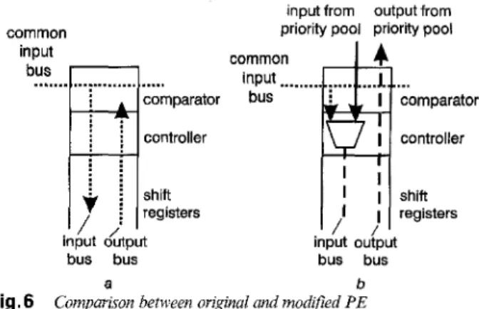
To be shared by all output ports the original OD1
sorter must be modified to add the load function. By using the load function, each PE of the OD1 sorter can load the initial value in parallel from the priority pool. After the new priority of each output queue has been generated by the subtractor, it is inserted to high-speed sorter and routed to a suitable rank. It costs an extra
data bus and some control logic to provide a load func- tion for each PE. The comparison between the original and the modified PE is shown in Fig. 6 .
common input bus
...
7) comparator controller . :. .
. .
. .
. .
i shift i registersinput from output from
priority pool priority pool
common
input
..
bus
input &put iniut ouiput
bus bus bus bus
a b
Comparison between original and modified PE Fig.6
a PE of original OD1 sorter
b PE of modified OD1 sorter
data in 1 data in 2 input data processor control
...
(insert/delete/ shift shift
load)
I
I
....
comparator controller shift registers data in N comparator controller shift registerI
normalisecontrol normalise circuit
J
output data
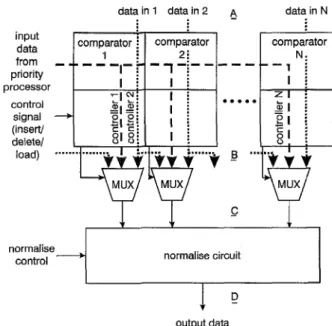
Fig.7 Block diugrum of modified ODI sorter
The renormalised function can be achieved by setting the normalisation bit to ‘1’ which can be realised by a normalisation network before the priority values are restored to priority pool. The block diagram of the modified OD1 sorter is shown in Fig. 7.
Whenever an output request arrives, the correspond- ing priority data of the output port is read out from the priority pool. The output queue with the highest priority is sent to output stage, and its priority value and cost value processed by the subtractor. The prior- ity values and corresponding information of other queues are loaded into a modified OD1 sorter. The PE with the highest rank of ODI sorter must be fed with the maximum number when load signal is turned on. It causes the contents of this PE to be shifted out during the sorting stage and the proper ranks of queues can be preserved. After loading, the new priority value of out- put queue generated by subtractor will be inserted into the hardware sorter, and the new links among queues can be generated and restored to the priority pool.
Indeed, the ODI sorter can route input data to its corresponding rank during a single cycle. By adding the load function it can achieve the priority sorting func- tion of an output port every two cycles (first cycle for load, the second for sort). Clock rate of the original OD1 sorter can reach 5OMHz in 1 . 2 ~ CMOS. It is expected that the throughput of the modified OD1
415 IEE Proc-Commun., Vol. 144, No. 6, December 1997
sorter
can reach more
than 25 M output requests per second (lO.GGbit/s,if
each port outputs a 53-byte ATM cell) by using the same CMOS process. This per- formance is fast enough for modern ATM systems.The priority pool can be implemented by using embedded memory. If the system clock is 50MHz, a single-port SRAM architecture can meet the speed requirement of the high-speed sorter. In many cases, the output candidates are determined port by port. Therefore we can use a FIFO to realise the priority pool.
The subtractor and other peripheral circuits can eas- ily be realised by cell-based design. They are not a crit- ical part of the complete system.
4 Improved method
As the discussion in Section 3.2, the modified OD1 sorter need two stages to process a sort function. The timing bottleneck of this architecture lies in that the priority data must be loaded into shifter registers first and then read out to compare with input value on glo- bal input bus. The read-after-write procedure of prior- ity data makes it difficult to add a pipeline register. It needs at least two cycles to perform a priority sort. In addition, the synchronous shift operations in shift reg- isters will also result in a larger peak current and power consumption.
We propose another architecture to break the timing bottleneck of the ODI-based architecture. By reorganis- ing the data flow and using multiplexers for the data routing function performed by shift registers in OD1 architecture, a faster priority sorter can be obtained as shown in Fig. 8.
data In 1 datain 2
A
data in Ninput data from priority processor control signal (insert/ delete/ load) , -
..
comparator - 1 I.. g i MUX _c I I normalisecontrol normalise circuit
output data
Fig. 8 Block diagram of multiplexer bused ODI sorter
The priority data in this architecture is applied to the comparator directly. The new priority value of the out- put candidate is applied to the global input bus to com- pare with those priority data. Instead of using shift registers, the priority data is provided by the output bus of priority pool. It reduces one clock cycle because loading priority data into shift registers can be avoided. The sorting of priority values can be done in one single cycle. In addition, pipeline registers can be added in A , B, C or
D
(as shown in Fig. 8) to enhance the system performance.The PE structure is shown
in
Fig.9. The
shift regis- ters are omitted, and three tristate buffer sets form the multiplexer to perform the data routing function. The chip area and power consumption can be reduced greatly by removing the register cells and their synchro- nous shift operations. It is estimated that the system performance of this enhanced architecture is double than the architecture proposed in Section 3.2. Based on previous research [I], for ATM systems with less then 64 delay QoSs, the estimated throughput of this enhanced architecture is more than 50 M output requests per second (21.2 Gbitis) by using the same1 . 2 ~ CMOS process.
from priority FIFO
global input bus
- - - -
comparator
to right PE
to right PE
output data
Fig.9 Structure of multiplexer based ODIsortevS PE
5
DiscussionThe QoS management algorithm and its corresponding VLSI architectures proposed deal with the queue level priority management function of the ATM switch. If the internal buffer of the ATM switch system is small, it is possible to provide the priority managing function of each cell in a reasonable hardware cost. For such architecture, one must provide a priority sorter for each output port. By providing the priority managing function at cell level, each connection is assigned to dif- ferent priority values in a more flexible way.
external master/
input slave
priority
to output stage
from left moduk sorter to right module
Fig. 10 Structure of cuscuduble QoS management module
The basic QoS management architecture can be expanded to a cascadable version easily. Both priority pool and OD1 sorter are cascadable inherently. The whole system only needs a priority processor (substrac- tor) to process the priority value of the output candi- date. We use two sets of tristate buffers controlled by the mastedslave control signal to enable/disable the pri- ority processor of QoS management module. The struc- ture of the cascadable QoS management module is shown in Fig. 10. The slave mode module will disable the priority processor by turning off the tristate buffers and the PE of sorter with the highest rank will not be fed with the maximum number. The master mode mod- ule works as an original module as discussed in previ- ous Sections.
There are two cascading styles of the basic module, one is for more QoSs per port, the other is for more ATM ports. Both cascading styles are shown in Figs. 11 and 12. The basic modules can be cascaded by shar- ing the output bus, priority bus, normal control signal, and cascading the sorters to realise a large system for more QoS numbers per port. In this cascading style, shown in Fig. 11, only one module is set to master mode, the others are in slave mode. The system for more ATM ports can be realised by sharing the output bus and using a decoder to set the corresponding
external input slave external input slave
, ...
1 I ; J
~ ...I ;
...,I
outputstagebus1
outputstagebusI
i
...
i...
ii i
I
new priorityI
new priority Ivalue bus valuebus
j i
L - - - , :
I
from leftI
from left !i module ! module 4
p
to right j to right j module;
module1
; j ii
normalise controlI
normalise control1
C - - - ~ - - - l i
!
1 .
Fig. 11 Block diagram of cascading QoS management systems
module to master mode and the others are in slave mode as shown in Fig. 12. A more complex system with a larger QoS number and I/O ports can be realised by using these two cascading styles simultaneously.
Compared with the Chao and Uzun approach [7] which uses similar architecture in a hardware sorter to serve a single output port, our approach can serve a whole system instead of a single port. The hardware efficiency of our approach is higher than their design. The comparison between these two approaches is given in Table 2.
Table 2: Comparison between Chao's and the present authors' approaches
Chao Present authors
Sorting algorithm hardware insertion hardware insertion
Shared b y 1 port whole switch
Priority processor processor su btractor
Cascading static structure cascadable
capa bi I ity
sort sort
structure
Although the example of our architecture described in this paper uses a subtractor to process the priority
external input master
. . . .
newpriorityI
I+ value bus I ? ! I I I I I I I I I I I I I I I I I---
from left i module --f to right ! module normalise control---~---'
j external input decoderI
I output stage bus output stage bus j
...
a... ....I.......
.< new priority value bus new priority value bus ... ... from left module __t : normalise control , ... ... ...Fig. 12 Block diagram of cascading style for more ATMports
external input
I
...
output stage output stage busnew priority value bus ... from left module --* -; to right module i normdiae Control i ... I C -...
value, it can be replaced by another processing element to provide a more complex priority policy if necessary. The word length of priority value and cost value is a trade-off between hardware cost and precision in prior- ity assignment. The number of QoSs is limited by the word length of cost value, and the word length of pri- ority value must be large enough to prevent finite-pre- cision problem during computing priority values. If the word length of priority value and cost value are increased, the memory word length of priority sorter and priority pool will have to be increased too.
6 Conclusion
A novel architecture for ATM QoS management has been proposed. It provides a high-speed, cost-effective and cascadable solution for ATM QoS management. The throughput of this architecture is estimated to reach 50M output requests per second in 1 . 2 ~ CMOS. Complex QoS problems can be solved by cas- cading QoS modules to form a more powerful system. In addition, this architecture can be shared by whole switch system, making it very suitable to be used in centralised switch architecture (such as shared buffer ATM switch).
The OD1 sorter based architecture is very suitable to realise the priority queue. In applications like the ATM QoS manager that needs high-speed priority arbitration and flexible priority assignment, the OD1 architecture does provide a good solution. Currently a test chip based on the proposed architecture is under design and will be integrated into our shared-buffer ATM switch demo system.
7 Acknowledgment
The authors acknowledge the financial support from both NSC (NSCS6-2221 -E009-020) and Telecommuni- cation Laboratories (TL-86-7401) of Chunghwa Tele- com.
References
LEE, C.Y., HSIEH, P.W., and TSAI, J.M.: ‘High-speed median filter designs using shiftable content-addressable memory’, ZEEE
Trans. Circuits Syst. Video TechnoL, 1994, 4, (6), pp. 544-549
TSAI, J.M.: ‘Shift register array architectures for high-speed data sorting’. Master’s thesis, National Chiao Tung University, June
1993
KOZAKI, T.: ‘32 x 32 shared buffer type ATM switch VLSI’s for
B-ISDN’s’, IEEE J. Sel. Areas Commun., 1991, 9, (8), pp. 1239- 1247
ITOH, A., TAKAHASHI, W., NAGANO, H., KURI-
SAKA, M., and IWASAKI, S.: ‘Practical implementation and
packaging technologies for a large scale ATM switching system’,
ZEEE J. Sel. Areas Commun., 1991, 9, (8), pp. 1280-1288
GIACOPELLI, J.N., HICKEY, J.J., MARCUS, W.S., and SIN-
COSKIE. W.D.: ‘A hiph-performance self-routing broadband
packet switch architecture’, ZEEE J. Sel. Areas Commun., 1991. 9,
(8), pp. 1289-1298
McDYSAN, D.E.: and SPOHN, D.L.: ‘ATM theory and appllica- tion’ (McGraw-Hill, 1995), chap. 10
CHAO, H.J., and U”, N.: ‘A VLSI sequencer chip for ATM
traffic shaper and queue manager’, ZEEE .ISolid-State Circuits, .
1992. 27. (11). UP. 16361643
9 Appendix
9.7
I** port P is selected to output **I schedule (int p);
(struct priority-element
C-like description for proposed algorithm
{ int priority-value; I* priority value */ int cost; /* cost *I
cell ‘“cellptr; I* cell pointer *I
1;
I** define N ports priority pool, each port has m delay QoSs **I
struct priority-element priority-POOL[N] [m];
I* priority-POOL [p] [m-1] contain the queue has the highest priority *I
cell-output(priority-POOL[p] [m-l].cellptr);
I* cost-function0 reassigns the priority value through cost **I
priority-POOL[p] [m-l].priority-value=
cost-function(priority-POOL[p] [m-l].priority-value, priority-POOL [p] [m-l].cost);
/** check if the normalisation function is necessary to be processed **I
if (underflow(priority-POOL [p] [m-l].priority-value)~~ overflow(priority-POOL [p] [m-l].priority value)) sort (priority-POOL
b]);
1
1” end of algorithm description *I
9.2
Proof of eqns.I
and2
A p-bit integer is used to represent priority value and a q-bit integer to represent cost value. Suppose there are
N queues in an output port, the cost values of them are
D 1 ,
Dz,..., D,,
respectively. For a certain time period, due to the normalised mechanism, suppose the output times of a certain queue, is equal to UID,, where U is a large integer. Total output times of this port is equal to UID,. For a certain queue, the bandwidth is equal to normalise(priority-POOL [p]); 1 Dln - D m ( 3 ) ~~-
N N x = lE &
x=1The maximum number which can be represented by a p-bit integer is 2 p - 1. For a certain queue, the maxi-
mum output time before normalisation is ( 2 p - l)/D,.
The maximum cell delay occurs when the priority value of the queue with lowest priority is closed to a normal- ised threshold and the other queues’ priority values are all less than the maximum value. Thus
TANENBAUk: A.S.: ‘Modern operating systems’ (Prentice- Hall, 1992)