DOI: 10.1002/adfm.200600697
Efficient White-Electrophosphorescent Devices Based on a Single
Polyfluorene Copolymer**
By Fang-Iy Wu, Xiao-Hui Yang, Dieter Neher,* Rajasekhar Dodda, Ya-Hsien Tseng,
and Ching-Fong Shu*
1. Introduction
Polymer light-emitting diodes (PLEDs) have attracted con-siderable interest because of their easy processability in solu-tion, which allows the utilization of spin-coating and printing methods for the preparation of large-area display devices.[1]In
principle, the emission colors of polymers can be easily tuned through covalently binding a guest chromophore to an emissive polymeric host at appropriate doping levels, which typically re-sults in the partial or complete quenching of the host emission and the emergence of dye emission. By tuning the dye concen-tration to realize complete energy transfer, devices with im-proved efficiencies and saturated red, green, and blue (RGB) colors have been realized.[2] Several authors also reported white-light emission from dye-functionalized polymers.[3] For instance, Tu et al.[3a]have demonstrated that dichromatic white
light can be achieved from polyfluorene (PF) chemically doped with 1,8-naphthalimide segments at a very low concentration. The devices based on the copolymer exhibited a maximum luminance efficiency (LE) of 5.3 cd A–1 and a power con-version efficiency (PCE) of 2.8 lm W–1 at 6 V. A maximum
brightness of 11 100 cd m–2was reached at 13.2 V. By incorpo-rating a highly fluorescent 4,7-bis(4-(N-phenyl-N-(4-methyl-phenyl)amino)phenyl)-2,1,3-benzothiadiazole unit instead of the 1,8-naphthalimide unit as the orange species in the PF chain, the same group reported white-emitting PLEDs with a peak LE and PCE of 8.99 cd A–1and 5.75 lm W–1, respective-ly.[3b] The combination of blue emission from fluorene
seg-ments and orange emission from the dyes created the percep-tion of white light in the human vision system. Liu et al.[3c] successfully realized white-light electroluminescence (EL) composed of the contributions from the three primary colors by using a simple polymer emitter. The diode was based on a PF copolymer prepared by Suzuki copolymerization with small amounts of a green fluorescent chromophore attached to the side chains and a red fluorescent chromophore covalently bound to the polymer backbone. This device exhibited a maxi-mum brightness of 3786 cd m–2at 19.4 V and a maximum LE
of 1.59 cd A–1. By using Yamamoto copolymerization, Lee et al.[3d]prepared a PF derivative having broadband emission covering the whole visible region. A white-light-emitting device based on this polymer showed a maximum brightness and a peak LE of 820 cd m–2and 0.1 cd A–1, respectively.
As demonstrated by the above mentioned examples, gener-ating whitish light from a single polymer emitter may provide a promising way to realize large-area lighting sources from sim-ple solution processing. However, significant improvements in device performances are needed with regard to the potential application of these devices. One approach to raise the EL effi-ciency is to incorporate phosphorescent dopants to harvest
lu-–
[*] Prof. D. Neher, Dr. F.-I. Wu, Dr. X.-H. Yang Institute of Physics, University of Potsdam Am Neuen Palais 10, 14469 Potsdam (Germany) E-mail: [email protected]
Prof. C.-F. Shu, Dr. F.-I. Wu, Dr. R. Dodda, Y.-H. Tseng
Department of Applied Chemistry, National Chiao Tung University 300 Hsinchu (Taiwan)
E-mail: [email protected]
[**] F.-I.W. thanks the National Science Council (NSC, Taiwan) and the Deutscher Akademischer Austausch Dienst (DAAD (Germany)) for a Sandwich scholarship and the members of the Soft Matter Physics group at the University of Potsdam for their kind support. D.N. and X.-H.Y. acknowledge the German Ministry of Science and Education (project number 13-N8213) for funding. Further financial support by the Fond der Chemischen Industrie and the State Brandenburg (Pro-ject CIMAT) is acknowledged. C.-F.S. thanks the National Science Council of Taiwan for financial support.
An efficient white-light-emitting polymer (W3) is realized by covalently attaching a green fluorophore and a red phosphor into the backbone and the side chains, respectively, of polyfluorene at a concentration of 0.04 mol %. In addition, charge-transport-ing pendant units are included to improve carrier injection and transport. White-electrophosphorescent devices with the structure ITO/PEDOT:PSS/W3/CsF/Al (ITO: indium tin oxide; PEDOT:PSS: poly(styrenesulfonate)-doped poly(3,4-ethylene-dioxythiophene)) exhibit a low turn-on voltage of 2.8 V and a luminance of ca. 103cd m–2at below 6 V. The peak luminance and power-conversion efficiencies are 8.2 cd A–1and 7.2 lm W–1, respectively. Furthermore, the device shows relatively stable white emission: the Commission Internationale d’Éclairage (CIE) chromaticity coordinates of the devices change only slightly from (0.35,0.38) at 10 mA cm–2to (0.33,0.36) at 100 mA cm–2, with an almost constant color render index (CRI) value of 82 at all measured current densities.
P
minescence from both singlet and triplet excited states.[4]
Apart from being polymeric hosts for fluorescent dyes,[5]PFs have been shown
to being suited for hosting red phosphores-cent dyes to realize highly efficient red-light-emitting PLEDs.[6] We reported white-emitting PLEDs using the blend of a PF host doped with a green-emitting PF derivative and a red-emitting Os phosphor as the emissive layer in the EL device with a configuration of indium tin oxide (ITO)/ poly(styrenesulfonate)-doped poly(3,4-ethylenedioxythiophene) (PEDOT:PSS)/ blend layer/1,3,5-tris(N-phenylbenzimida-zol-2-yl)benzene (TPBI)/Mg:Ag. This white-emitting device showed a relatively high LE of 8.3 cd A–1, but an unsatisfacto-ry PCE of 2.1 lm W–1due to a relatively high driving voltage.[7]Also, although the device exhibited efficient and color-stable white electrophosphorescence, the risk of phase-separation could not be completely avoided in such a blended device. There-fore, in this study we chemically incorpo-rated red phosphorescent and green fluo-rescent components into PF copolymers with the aim to develop a single
white-light-emitting polymer. The green- and red-emitting parts in these copolymers were formed by employing small amounts of 4,7-dibromo-2,1,3-benzothiadiazole and a new iridium-contain-ing monomer, respectively, duriridium-contain-ing copolymerization. A large amount of triphenylamine (TPA) and oxadiazole (OXD) moi-eties were introduced as the pendant groups of the dye-attached PFs.[8]The incorporation of TPAs and OXDs was reported to significantly lower the energy-barrier height for carrier injec-tion from the electrodes and improve the carrier-transporting properties in phosphor-doped PLEDs, leading to the improve-ment of EL performances.[6b,9] By carefully controlling the concentrations of the low-energy emitting species in the result-ing polymers and by utilizatresult-ing an efficient electron-injection cathode, white electrophosphorescence was achieved by the balanced emission of the three primary colors, with a full width at half-maximum (FWHM) of 205 nm and a peak LE of 8.2 cd A–1.
2. Results and Discussion
2.1. Synthesis and Characterization of M4 and Dye-Attached Copolymers W1–3
The synthetic route for the preparation of the dibromofluor-ene monomer, M4, is shown in Scheme 1. 5-Bromo-2-methyl-pyridine (1)[10]was treated with n-BuLi at –78 °C in dry ether and the resulting lithiated species was quenched with 2,7-dibro-mo-9-fluorenone and as such gave
2,7-dibromo-9-(2-methylpyr-idine-5-yl)fluoren-9-ol (2). The acid-promoted (CF3SO3H)
Friedel–Crafts reaction of 2 with benzene yielded 3, which in turn was oxidized using KMnO4in H2O/pyridine to afford
car-boxylic acid (4). Subsequent reaction of 4 with the cyclometa-lated chloride-bridged dimer (5)[11]in refluxing ethoxyethanol in the presence of Na2CO3 gave the desired monomer. As
shown in Scheme 1, M4 contains a
bis[1-phenylisoquinolinato-C2,N]iridium(III) picolinate [Ir(piq)] substituent at the sp3 car-bon (C-9) of fluorene, which serves as a spacer[8]to effectively block the conjugation between the Ir(piq) substituent and fluo-rene. Scheme 2 shows the synthesis of the dye-attached copoly-mers W1, W2, and W3 and the chemical structure of the green-light-emitting model compound 4,7-bis(9,9-dihexyl-fluoren-2-yl)-2,1,3-benzothiadiazole (DFBT). The OXD monomer M1, TPA monomer M2, 4,7-dibromo-2,1,3-benzothiadiazole (M3), and diboronate M5 were prepared according to reported pro-cedures.[8,12,13]The W1 copolymer was prepared by performing a Suzuki coupling reaction between the diboronate M5 and the dibromides M1, M2, M3, and M4 (in a mole ratio of 50:24.7:24.7:0.2:0.4), in which M3 and M4 were added quickly to the reaction flask from diluted CHCl3solutions (in
concen-trations of 1–3 × 10⁻³M), and the other reactants and solvents
were added after the CHCl3 solvent evaporated completely.
This copolymerization was undertaken using Pd(PPh3)4as the
catalyst in a mixture of toluene and 2.0Maqueous K2CO3in the
presence of methyltrioctylammonium chloride (Aliquat 336) as a phase-transfer reagent. When polymerization was com-plete, the end groups of the polymer chains were capped by heating under reflux sequentially with phenylboronic acid and
N Br CH3 n-BuLi/ether HO N CH3 Benzene/CF3SO3H O Br Br N CH3 Br Br Br N COOH Br Br 1 4 3 2 Br N Ir Cl Cl Ir N N O O N Ir Br Br 2 M4 Na2CO3/ 2-ethoxyethanol 2 2 5 KMnO4 water/pyridine
Scheme 1. Synthetic pathway for the synthesis of M4.
FULL
P
bromobenzene. W2 and W3 copolymers were prepared following the same procedure as described for the synthesis of W1, by Suzuki copolymerization of the diboronate M5 and the dibromides M1, M2, M3, and M4 in mole ratios of 50:24.85:24.85:0.15:0.15 and 50:24.96:24.96:0.04:0.04, respective-ly. The resultant PF copolymers are readily soluble in common organic solvents, such as toluene, chlorobenzene, chloroform, and tetrahydrofuran (THF). The number-average molecular weights (Mn) were determined to be 4.6 × 10⁴, 4.3 × 10⁴, and
4.7 × 10⁴g mol–1for W1, W2, and W3, respectively, with poly-dispersities of 1.72–1.77. The glass-transition temperatures (Tg)
of W1–W3 determined by differential scanning calorimetry (DSC) were ca. 170 °C, almost identical to that of PF-TPA-OXD.[8b]This implies that the attachment of the dyes in such small amounts does not significantly alter the rigidity of the re-sulting copolymers.
2.2. Optical Properties
The absorption spectra of W1, W2, and W3 are similar to that of PF-TPA-OXD (not shown here) in both solution and
the solid state, and the absorption contributions from the 2,1,3-benzothiadiazole (BT)-containing and iridium-containing moi-eties are not observable in the absorption spectra, due to the very small concentrations of these moieties in the copolymers. For the same reason, the photoluminescence (PL) spectra of W1, W2, and W3 in diluted THF solution (Fig. 1a) are similar to that of PF-TPA-OXD. However, the incorporation of BT-and iridium-containing moieties leads to a significant change in the luminescence properties of thin films. As indicated in Fig-ure 1b, the PL spectra of W1, W2, and W3 films spin-coated on quartz substrates contain, in addition to the backbone emis-sion, a strong emission band centered at 520 nm, which is the characteristic emission of the BT-containing segments, and a minor contribution from the triplet emission of the Ir(piq) sub-stituent at ca. 600 nm. As displayed in Figure 2, the PL spec-trum of PF-TPA-OXD overlaps with the absorption spectra of both M4 and DFBT, which may imply that there is efficient en-ergy transfer from the fluorene segments to the low-enen-ergy emitting segments in the dye-attached polymers. The enhanced green and red emission intensities in the PL spectra of the thin-film samples indicate that energy transfer from fluorene
seg-NN O O N N t-Bu t-Bu C8H17 C8H17 N N n-Bu n-Bu n-Bu n-Bu C8H17 C8H17 X Y N S N C8H17 C8H17Z C8H17 C8H17 W N O O N Ir N O O N Ir Br Br NN O O N N t-Bu t-Bu Br N N n-Bu n-Bu n-Bu n-Bu NSN C8H17 C8H17 Br Br Br Br Br B B O O O O 2 2
+
+
+
+
Pd(PPh3)4/K2CO3 toluene/H2O/Aliquat 336 W1 X=Y=0.247n, Z=0.002n, W=0.004n; W2 X=Y=0.2485n, Z=0.0015n, W=0.0015n; W3 X=Y=0.2496n, Z=0.0004n, W=0.0004n. M1 M2 M3 M4 M5 N S N DFBTScheme 2. Synthetic pathways for the dye-attached copolymers and the chemical structure of DFBT.
P
ments to the low-energy emitting segments is facilitated through both intra- and interchain channels. As expected, the green or red emission intensities decrease as the loading con-centration decreases. In comparison with the intensity in the PL spectrum of W2, the green emission of W3 is approximately decreased by a factor of 4, which is consistent with the reduc-tion of the feeding ratios of M3 and M4.
2.3. Cyclic Voltammetry Measurements
Cyclic voltammetry (CV) measurements of the model com-pound DFBT and monomer M4 were carried out to obtain in-formation about the energy levels of the green-light and
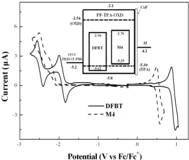
red-light-emitting parts of the PF copolymers, which then allows to draw some general conclusions about the charge-transporting mechanisms in EL devices. For DFBT, the first reduction at –1.91 V occurs predominately at the electron-deficient ben-zothiadiazole core;[14] while the second reduction at –2.48 V and the first oxidation at 0.92 V takes place along the conjugat-ed 1,4-bis(9,9-dihexyl-fluoren-2-yl)-benzene, as the rconjugat-edox po-tentials are close to those of terfluorenes.[15]The reduction and oxidation onset potentials of DFBT are –1.84 V and 0.82 V, re-spectively. For M4, an irreversible reduction, which occurs pri-marily on the electron-accepting heterocyclic portion of the cy-clometalated piq ligands, was observed with the onset potential at –2.04 V, and a reversible oxidation, which mainly occurred at the Ir metal site, was found at 0.53 V with an onset potential of 0.45 V.[16]On the basis of the onset potentials of the oxida-tions and reducoxida-tions, we estimated the highest occupied molec-ular orbital (HOMO) and lowest unoccupied molecmolec-ular orbital (LUMO) levels of DFBT and M4 with regard to the energy lev-el of ferrocene (4.8 eV blev-elow vacuum).[17]The HOMO/LUMO levels of DFBT and M4 are calculated to be –5.62/–2.96 eV and –5.25/–2.76 eV, respectively. The inset of Figure 3 shows the energy level diagram for the complete devices based on the CV measurements of M4, DFBT, and PF-TPA-OXD.[6b,8b] Ac-cording to this diagram, both the BT-containing fluorophore and iridium-containing phosphor function as electron traps in the PF-TPA-OXD host; in addition, the phosphor may act as a weak trap for holes.
2.4. EL Properties
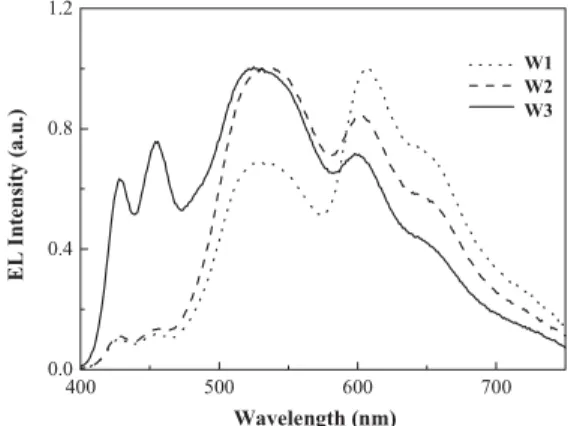
EL spectra of W1-, W2-, and W3-based devices are shown in Figure 4. Compared with the PL spectra in the solid state, the contributions from both of the green- and red-light-emitting moieties are dramatically enhanced in the EL spectra. The
Figure 1. PL spectra of W1, W2, and W3 in a) dilute THF solutions and
b) in the solid state. The excitation wavelength was 380 nm.
350 400 450 500 550 600 650 0.0 0.3 0.6 0.9 1.2 0.0 0.3 0.6 0.9 1.2 PL In te nsi ty ( a .u .) A b s Int e nsi ty (a .u .) Wavelength (nm) PF-TPA-OXD DFBT M4
Figure 2. PL spectrum of PF-TPA-OXD in the solid state (excited at
380 nm) and the absorption spectra of DFBT and M4 in CHCl3solution.
Figure 3. Cyclic voltammograms of DFBT and M4. The inset displays the
proposed energy-level scheme for the devices having the configuration ITO/PEDOT:PSS/polymer/CsF/Al.
FULL
P
large difference between the EL and PL spectra indicates that the low-energy emitting segments act as charge-trapping sites, which is commonly observed in organic host–guest systems.[18]
In a previous study, however, we noted that low-energy emit-ting species doped into a PF-TPA-OXD host, with similar trap-ping depths (ca. 0.1–0.3 eV), were not preferentially populated in EL (compared to PL).[6b]These devices utilized a Mg:Ag al-loy cathode and a TPBI electron-transporting/hole-blocking layer. The density and distribution of carriers in the emission layer are probably rather different in the devices with a CsF/Al cathode from those in previous studies. Further experiments are required to understand the working mechanism of the de-vices.
The EL spectrum of the W3-based device possesses well-bal-anced contributions from all three primary colors and thus cov-ers the whole visible region with a FWHM of 205 nm. Commis-sion Internationale d’Éclairage (CIE) chromaticity coordinates (x,y) for the W3-based device are (0.34,0.38) for an operating current density of 20 mA cm–2, which is located very close to the white point (0.33,0.33). At this current density, the devices show a color temperature of ca. 6000 K and a color render in-dex (CRI) value of 82. As expected, the relative blue emission intensity in the EL spectrum is rather sensitive to the concen-trations of the low-energy emitting segments.
The current-density–voltage–luminance (J–V–L) characteris-tics of the devices are shown in Figure 5. The J–V curves are clearly shifted to higher voltages as the proportions of the low-energy emitting moieties increase. This is consistent with the charge-trapping mechanism proposed above on the basis of CV measurements and the observation of a significant differ-ence between the EL and PL spectra.
The turn-on voltages (the voltage required for 0.01 cd m–2)
for W1-, W2-, and W3-based devices are around 3 V. The peak
LEs for the devices are between 7 and 8.5 cd A–1, correspond-ing to external quantum efficiencies of 3–4 %, dependcorrespond-ing on the EL spectrum of the respective device. The operating volt-ages acquired to achieve a brightness of 103cd m–2are
relative-ly low, typicalrelative-ly at around 6–7 V. In particular, as shown in
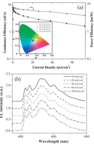
Fig-ure 6a, the maximum LE and PCE of the white-light-emitting device based on W3 is 8.2 cd A–1(corresponding to an external quantum efficiency of 3.7 %) and 7.2 lm W–1 at a voltage of 3.6 V, a current density of 0.13 mA cm–2 and a brightness of 11 cd m–2. We believe that the decrease of the luminance
effi-ciency with increasing current density can partially be attribut-ed to the triplet–triplet annihilation process. However, at the moment we can not exclude contributions by other processes such as the dissociation of excitons by the electric field or ef-fects related to the width and location of the recombination zone as a function of bias.
At a bias of 6.0 V, this device reaches a brightness of 1330 cd m–2while a LE of more than 6 cd A–1is still retained. This is higher than the LEs of most white-light EL devices pre-pared from a single fluorescent polymeric emitter at compar-able brightness levels.[3] Moreover, the EL spectra of our white-light PLEDs are almost independent of driven current density from 10 to 100 mA cm–2 (see Fig. 6b). As shown in the inset of Figure 6a, there is only a minor shift of the CIE coordinates from (0.35,0.38) at a brightness of 670 cd m–2
(10 mA cm–2) to (0.33,0.36) at a brightness of 4200 cd m–2 (100 mA cm–2). Thus, the color point remains in the
white-light-region and is close to the equal-energy white point (0.33,0.33). In addition, the CRI values of the device were nearly unchanged from 10 mA cm–2to 100 mA cm–2.
3. Conclusions
We have demonstrated efficient white-light electrophospho-rescence from a copolymer containing both hole-transporting and electron-transporting groups, with a small concentration of BT-containing segments and iridium complexes covalently linked to the bipolar polyfluorene. In a single emissive layer device configuration, white light was emitted at voltages as low as 2.8 V. The maximum LE and PCE were 8.2 cd A–1 and 7.2 lm W–1, respectively. The resulting white-light
electrolumi-nescence showed contributions from all three primary colors, W1 W2 400 500 600 700 0.0 0.4 0.8 1.2 E L In te ns it y (a .u .) Wavelength (nm) W3
Figure 4. EL spectra of W1-, W2-, and W3-based devices at an operating
current density of 20 mA cm–2. 0 2 4 6 8 0 50 100 150 W1 W2 W3 Voltage (V) Cur rent Dens it y (m A /c m 2 ) 10-2 10-1 100 101 102 103 104 Br ig htnes s (cd /m 2 )
Figure 5. Plots of the current density and luminance as a function of the
applied voltage for W1-, W2-, and W3-based devices.
P
with the CIE coordinates close to the equal-energy white point and with CRI values above 80. The CIE and CRI values re-mained stable when the brightness increased from 670 cd m–2 to 4200 cd m–2. We note that the external quantum efficiency of
our devices is still lower than that of white-light-emitting de-vices using a Pt-complex-grafted non-conjugated polymer.[19]
We expect that the EL efficiency can be improved further if phosphors with higher triplet energies (green or blue phos-phors) are covalently linked to a host polymer having a wide bandgap.[20]
After the completion of this Full Paper, we noted that similar white-light-emitting polymers containing red phosphor and green fluorophore units were reported by Cao and co-workers.[21]
4. Experimental
4.1. Materials and Characterization
5-Bromo-2-methylpyridine (1) [10], and monomers M1 [8a], M2 [8b], M3 [12], and M5 [13] were prepared according to reported
proce-dures. The solvents were dried using standard proceproce-dures. All other re-agents were used as received from commercial sources, unless other-wise stated.
1H and13C NMR spectra were recorded on a Bruker-DRX 300
(300 MHz for1H and 75 MHz for13C) spectrometers. Size-exclusion
chromatography (SEC) was performed using a Waters chromatography unit interfaced with a Waters 410 differential refractometer; three 5 lm Waters styragel columns (300 mm × 7.8 mm) were connected in series in order to decrease the pore size (104, 103, and 102Å); THF was the
eluent. Standard polystyrene samples were used for calibration. Differ-ential scanning calorimetry (DSC) was performed using a Seiko Exstar 6000DSC unit at a heating rate of 20 °C min–1and a cooling rate of 40 °C min–1. Samples were scanned from 30 to 330 °C, cooled to 0 °C, and then scanned again from 30 to 330 °C. The glass-transition temper-atures (Tg) were determined from the second heating scan. UV-vis
spectra were measured using a HP 8453 diode-array spectrophotome-ter. PL spectra were obtained from a Hitachi F-4500 luminescence spectrometer. Cyclic voltammetry measurements were performed using a BAS 100B/W electrochemical analyzer. The oxidation and reduction potentials were measured, respectively, in anhydrous CH2Cl2and THF,
containing 0.1Mtetrabutylammonium hexafluorophosphate (TBAPF6)
as the supporting electrolyte, at a scan rate of 50 mV s–1. The potentials were measured against a Ag/Ag+(0.01MAgNO3) reference electrode
using ferrocene as the internal standard. The onset potentials were de-termined from the intersection of two tangents drawn at the rising cur-rent and background curcur-rent of the cyclic voltammogram.
4.2. Syntheses
2,7-Dibromo-9-(2-methylpyridin-5-yl)fluoren-9-ol (2): To a stirred
solution of 5-bromo-2-methylpyridine (1) (2.00 g, 11.7 mmol) in dry ether (80 mL) was added dropwise n-BuLi (5.3 mL, 13.3 mmol, 2.5M
in hexanes) at –78 °C over 20 min. The resulting mixture was stirred at –78 °C for 10 min and at 0 °C for 30 min. The mixture was again cooled to –78 °C, and solid 2,7-dibromo-9-fluorenone (3.89 g, 11.5 mmol) was added in three portions over a period of 20 min. The solution was then allowed to warm to room temperature and stirring was continued over-night. The reaction contents were then quenched with water and di-luted with ethyl acetate. The organic phase was washed with excess water and dried over MgSO4. Concentration of the ethyl acetate
solu-tion followed by recrystallizasolu-tion with hexane/ethyl acetate afforded 2 (4.10 g, 82.7 %).1H NMR (300 MHz, CDCl3): d [ppm]: 2.37 (s, 3H), 5.16 (s, 1H), 7.01 (d, 1H, J = 8.1 Hz), 7.31 (d, 2H, J = 1.7 Hz), 7.38 (d, 2H, J = 8.0), 7.44 (dd, 2H, J = 8.0, 1.7 Hz), 7.53 (dd, 1H, J = 8.1, 2.3 Hz), 7.90 (d, 1H, J = 2.3 Hz).13C NMR (75 MHz, CDCl 3): d [ppm]: 23.3, 81.5, 121.6, 122.6, 123.3, 128.3, 132.5, 134.3, 135.4, 137.4, 145.3, 151.8, 157.1. HRMS (m/z): [M+] calcd. for C19H1379Br2NO, 428.9364; found
428.9362.
2,7-Dibromo-9-(2-methylpyridin-5-yl)-9-phenylfluorene (3): To a
so-lution of 2 (2.00 g, 4.64 mmol) in dry benzene (15 mL) at 50 °C, tri-fluoromethanesulfonic acid (0.82 mL, 9.28 mmol) was added dropwise under nitrogen. The mixture was then refluxed for 4 h. After this peri-od, the reaction mixture was poured into a saturated sodium bicarbo-nate solution and extracted with ethyl acetate. The organic layer was washed with brine and water and dried over MgSO4. The solvent was
evaporated and purified by column chromatography using CH2Cl2for
elution to provide 3 (1.63 g, 71.5 %).1H NMR (300 MHz, CDCl 3): d [ppm]: 2.52 (s, 3H), 7.04 (d, 1H, J = 8.2 Hz), 7.10–7.13 (m, 2H), 7.25– 7.28 (m, 3H), 7.34 (dd, 1H, J = 8.2, 2.3 Hz), 7.46 (d, 2H, J = 1.7 Hz), 7.49 (dd, 2H, J = 8.1, 1.7 Hz), 7.59 (d, 2H, J = 8.1 Hz), 8.30 (d, 1H, J = 2.3 Hz). 13C NMR (75 MHz, CDCl 3): d [ppm]: 24.1, 63.5, 121.9, 122.1, 123.1, 127.6, 127.8, 128.9, 129.3, 131.4, 135.9, 137.3, 138.1, 143.4, 148.5, 152.2, 157.3. HRMS (m/z): [M+] calcd. for C25H1779Br2N, 488.9727; found 488.9766. 9-(2-Carboxypyridin-5-yl)-2,7-dibromo-9-phenylfluorene (4): To a
re-fluxed solution of 3 (1.00 g, 2.04 mmol), pyridine (15 mL), and water (3.0 mL), solid KMnO4(4.80 g, 30.6 mmol) was added in ten portions
over 4 days. After this period, the reaction mixture was filtered and the filtrate was acidified with conc. HCl to pH 3.0; the precipitated solid was then filtered and washed with excess water. The dried solid was
0 30 60 90
0.1 1 10
Current Density (mA/cm2)
L u m in a nce Ef fi cien cy ( cd/A) 0.1 1 10 Powe r E ff ic ie n cy ( lm /W ) 400 600 800 0.0 0.5 1.0 1.5 2.0 2.5 10 mA/cm2 20 mA/cm2 40 mA/cm2 60 mA/cm2 100 mA/cm2 Wavelength (nm) EL Intensi ty (a. u .)
(b)
(a)
0 0.2 0.6 0.8 X Y 0.4 0 0.2 0.4 0.6 0.8Figure 6. a)LE and power conversion efficiency as a function of current
density for a W3-based device. The inset shows the CIE coordinates (x,y)
of a W1- and W2-based device at 20 mA cm–2and a W3-based device at a
current density of 10, 40, and 100 mA cm–2. b) EL spectra of a W3-based
device at different current densities.
FULL
P
subjected to column chromatography (hexane/ethyl acetate, 8:2; hex-ane/acetone, 8:2) to afford 4 (0.30 g, 28.2 %). 1H NMR (300 MHz, CDCl3): d [ppm]: 7.06–7.18 (m, 2H), 7.29–7.40 (m, 3H), 7.47 (s, 2H), 7.56 (d, 2H, J = 8.1 Hz), 7.66 (d, 2H, J = 8.1 Hz), 7.74 (d, 1H, J = 7.9 Hz), 8.13 (d, 1H, J = 7.9 Hz), 8.44 (s, 1H).13C NMR (75 MHz, CDCl3): d [ppm]: 63.8, 122.2, 122.5, 123.7, 127.7, 128.1, 129.2, 129.3, 132.0, 137.7, 138.1, 142.4, 144.9, 145.9, 147.7, 151.0, 163.9. HRMS (m/z): [M+] calcd. for C 25H1579Br2NO2, 518.9470; found 518.9526.
Synthesis of Monomer M4: A mixture of the
phenylisoquinoline-based iridium dimer [11] 5 (147 mg, 115 lmol), 4 (146 mg, 280 lmol), Na2CO3 (122 mg, 1.15 mmol), and 2-ethoxyethanol (3.0 mL) was
heated at 100 °C for 24 h under a nitrogen atmosphere. After cooling to room temperature, the precipitate was filtered off and washed with hexane and ethanol, and purified by recrystallization from a mixture of CH2Cl2 and ethanol to yield M4 (201 mg, 78.9 %). 1H NMR
(300 MHz, CDCl3): d [ppm]: 6.20 (dd, 1H, J = 7.8, 0.9 Hz), 6.31 (dd, 1H, J = 7.8, 1.2 Hz), 6.53 (td, 1H, J = 7.4, 1.2 Hz), 6.63 (td, 1H, J = 7.6, 1.2 Hz), 6.65–6.73 (m, 3H), 6.90 (td, 1H, J = 7.7, 1.2 Hz), 6.98 (d, 1H, J = 1.8 Hz), 6.99–7.04 (m, 2H), 7.16–7.19 (m, 2H), 7.21 (s, 1H), 7.27 (d, 1H, J = 1.5 Hz), 7.39 (dd, 1H, J = 8.4, 2.1 Hz), 7.41 (dd, 1H, J = 8.4, 1.8 Hz), 7.48 (td, 2H, J = 8.1, 1.8 Hz), 7.51 (d, 1H, J = 8.4 Hz), 7.52 (d, 1H, J = 8.1 Hz), 7.66–7.78 (m, 5H), 7.83–7.95 (m, 3H), 8.09 (dd, 1H, J = 8.1, 0.6 Hz), 8.15 (d, 1H, J = 8.1 Hz), 8.72 (d, 1H, J = 6.3 Hz), 8.84– 8.94 (m, 2H).13C NMR (75 MHz, CDCl 3): d [ppm]: 63.3, 120.6, 120.7, 120.8, 121.2, 121.97, 121.98, 122.1, 122.3, 126.0, 126.3, 126.8, 127.0, 127.2, 127.3, 127.5, 127.6, 127.9, 128.0, 128.68, 128.74, 128.8, 130.1, 130.2, 130.99, 131.03, 131.70, 131.74, 132.5, 133.1, 135.0, 136.8, 137.0, 137.8, 137.9, 139.7, 140.9, 142.3, 145.4, 146.0, 146.2, 149.2, 150.1, 150.3, 150.5, 151.2, 152.5, 168.2, 170.3, 172.4. HRMS (m/z): [M++H] calcd. for
C55H3579Br2N3O2Ir, 1120.0725; found 1120.0721. Anal. calcd. for
C55H34Br2N3O2Ir: C, 58.98; H, 3.06; N, 3.75. Found: C, 58.59; H, 3.60;
N, 3.71.
4,7-bis(9,9-dihexyl-fluoren-2-yl)-2,1,3-benzothiadiazole (DFBT): A
mixture of 4,7-dibromo-2,1,3-benzothiadiazole (90 mg, 306 lmol), 2-(9,9-dihexyl-fluoren-7-yl)-4,4,5,5-tetramethyl-1,3,2-dioxaborolane [22] (330 mg, 513 lmol), Aliquat 336 (ca. 9 mg), aqueous K2CO3 (2.0M,
2.0 mL), and toluene (10 mL) was degassed; then tetrakis(triphenyl-phosphine)palladium (ca. 8 mg) was added under vigorous nitrogen flushing. After heating at 105 °C for 12 h, the reaction mixture was poured into water (10 mL) and extracted with EtOAc (10 mL ×2). The organic extracts were dried (MgSO4) and concentrated under reduced
pressure. The residue was purified by column chromatography (dichlo-romethane/hexane, 1:4) to afford DFBT (156 mg, 63.6 %).1H NMR (300 MHz, CDCl3): d [ppm]: 0.69 (m, 20H), 0.95–1.09 (m, 24H), 1.88–2.03 (m, 8H), 7.22–7.32 (m, 6H), 7.70 (dd, 2H, J = 5.9, 1.7 Hz), 7.79 (d, 2H, J = 8.4 Hz), 7.81 (s, 2H), 7.88 (d, 2H, J = 0.9 Hz), 7.94 (dd, 2H, J = 8.0, 1.7 Hz).13C NMR (75 MHz, CDCl3): d [ppm]: 14.0, 22.6, 23.8, 29.7, 31.5, 40.3, 55.2, 119.7, 120.0, 122.9, 123.9, 126.8, 127.2, 127.9, 128.1, 133.6, 136.2, 140.7, 141.3, 151.1, 151.3, 154.4. HRMS (m/z): [M+] calcd. for C56H68N2S, 800.5103; found 800.5109.
4.3. General Procedures of Polymerization
W1 is taken as an example. To a solution of M1 (50.0 mg, 57.0 lmol), M2 (59.1 mg, 57.0 lmol), M3 (173 lL, 2.54 × 10⁻³
M in CHCl3,
0.44 lmol), M4 (690 lL, 1.33 × 10⁻³
M in CHCl3, 0.92 lmol), and M5
(74.1 mg, 115.3 lmol) in toluene (2.0 mL) were added aqueous potas-sium carbonate (2.0M, 1.0 mL) and Aliquat 336 (30 mg). The above so-lution was degassed, and tetrakis(triphenylphosphine)palladium (ca. 3 mg) was added in one portion under a nitrogen atmosphere. The solution was stirred at 90–95 °C for 36 h. The end groups were capped by refluxing for 12 h each with phenylboronic acid (17 mg, 140 lmol) and bromobenzene (22 mg, 140 lmol). After this period, the mixture was cooled and poured into a mixture of methanol and water (50 mL, 2:1 v/v). The crude polymer was filtered, washed with excess methanol, and dried. The polymer was dissolved in CHCl3and precipitated twice
in methanol. The precipitate was collected, washed with acetone for 24 h using a Soxhlet apparatus, and dried under vacuum. The yield was 77.8 %. 1H NMR (300 MHz, CDCl3): d [ppm]: 0.63–0.80 (20H, m),
0.81–0.95 (12H, m), 0.96–1.20 (40H, m), 1.24–1.40 (26H, m), 1.54 (8H,
m), 2.02 (8H, m), 2.51 (8H, m), 6.80–7.11 (24H, m), 7.45–7.89 (30H, m), 7.92–8.16 (10H, m).
W2 (84.5 % yield) and W3 (83.0 % yield) were prepared following
the same procedure as described for the synthesis of W1 using Suzuki coupling reactions between the diboronate M5 and the dibromides M1,
M2, M3, and M4 in mole ratios of 50:24.85:24.85:0.15:0.15 and
50:24.96:24.96:0.04:0.04, respectively. Because the contents of ben-zothiadiazole (BT)- and Ir-containing moieties in the PF copolymers are too low for NMR detection, the W1–W3 copolymer exhibited the same1H spectra as that obtained for the parent PF-TPA-OXD.
4.4. Fabrication of Light-Emitting Devices
The EL devices were fabricated on pre-cleaned and O2-plasma
treat-ed indium tin oxide (ITO) substrates. A layer of 70 nm-thick poly(styr-enesulfonate)-doped poly(3,4-ethylenedioxythiophene) (PEDOT:PSS) was first spin-coated from its aqueous solution and baked at 80 °C for 30 min to remove the residual water. Then a layer of copolymer was deposited on top of the PEDOT:PSS layer from chlorobenzene solu-tion. The resulting layer thickness was 70 nm as measured with a Dek-tak profilometer. The samples were annealed at 80 °C for 30 min [23]. The devices were completed by thermal deposition of a CsF (1 nm)/Al (100 nm) cathode. Current–voltage characteristics were measured with a Keithley 2400 SourceMeter. The brightness of the devices was re-corded with a Minolta CS-100 A ChromaMeter. EL spectra were mea-sured using a charge-coupled device fiber spectrometer (Ocean Optics HR2000). With exception of the deposition of the PEDOT:PSS layer, all processes were carried out in a dry nitrogen atmosphere.
Received: August 2, 2006 Final version: October 29, 2006 Published online: March 8, 2007
–
[1] R. H. Friend, R. W. Gymer, A. B. Holmes, J. H. Burroughes, R. N. Marks, C. Taliani, D. D. C. Bradley, D. A. Dos Santos, J. L. Brédas, M. Lögdlund, W. R. Salaneck, Nature 1999, 397, 121.
[2] a) J. Morgado, F. Cacialli, R. H. Friend, R. Iqbal, G. Yahioglu, L. R. Milgrom, S. C. Moratti, A. B. Holmes, Chem. Phys. Lett. 2000, 325, 552. b) C. Ego, D. Marsitzky, S. Becker, J. Zhang, A. C. Grimsdale, K. Mullen, J. D. MacKenzie, C. Silva, R. H. Friend, J. Am. Chem.
Soc. 2003, 125, 437. c) X. W. Chen, J. L. Liao, Y. M. Liang, M. O.
Ahmed, H. E. Tseng, S. A. Chen, J. Am. Chem. Soc. 2003, 125, 636. d) H.-J. Su, F.-I. Wu, Y.-H. Tseng, C.-F. Shu, Adv. Funct. Mater. 2005,
15, 1209.
[3] a) G. Tu, Q. Zhou, Y. Cheng, L. Wang, D. Ma, X. Jing, F. Wang, Appl.
Phys. Lett. 2004, 85, 2172. b) J. Liu, Q. G. Zhou, Y. X. Cheng, Y. H.
Geng, L. X. Wang, D. G. Ma, X. B. Jing, F. S. Wang, Adv. Funct.
Ma-ter. 2006, 16, 957. c) J. Liu, Q. Zhou, Y. Cheng, Y. H. Geng, L. Wang,
D. Ma, X. Jing, F. Wang, Adv. Mater. 2005, 17, 2974. d) S. K. Lee, D.-H. Hwang, B.-J. Jung, N. S. Cho, J. Lee, J.-D. Lee, H.-K. Shim, Adv.
Funct. Mater. 2005, 15, 1647.
[4] a) M. A. Baldo, D. F. O’Brien, Y. You, A. Shoustikov, S. Sibley, M. E. Thompson, S. R. Forrest, Nature 1998, 395, 151. b) M. A. Baldo, S. Lamansky, P. E. Burrows, M. E. Thompson, S. R. Forrest, Appl.
Phys. Lett. 1999, 75, 4.
[5] a) T. Virgili, D. G. Lidzey, D. D. C. Bradley, Adv. Mater. 2000, 12, 58. b) R. W. T. Higgins, A. P. Monkman, H. G. Nothofer, U. Scherf,
Appl. Phys. Lett. 2001, 79, 857.
[6] a) F.-C. Chen, Y. Yang, M. E. Thompson, J. Kido, Appl. Phys. Lett.
2002, 80, 2308. b) F.-I. Wu, P.-I. Shih, Y.-H. Tseng, G.-Y. Chen, C.-H.
Chien, C.-F. Shu, Y.-L. Tung, Y. Chi, A. K.-Y. Jen, J. Phys. Chem. B
2005, 109, 14 000. c) F.-I. Wu, P.-I. Shih, C.-F. Shu, Y.-L. Tung, Y. Chi,
Macromolecules 2005, 38, 9028.
[7] F.-I. Wu, P.-I. Shih, Y.-H. Tseng, C.-F. Shu, Y.-L. Tung, Y. Chi, J. Mater.
Chem. 2007, 17, 167.
[8] a) F.-I. Wu, D. S. Reddy, C.-F. Shu, M. S. Liu, A. K.-Y. Jen, Chem.
Mater. 2003, 15, 269. b) C.-F. Shu, R. Dodda, F.-I. Wu, M. S. Liu,
A. K.-Y. Jen, Macromolecules 2003, 36, 6698.
P
[9] a) X. H. Yang, D. Neher, Appl. Phys. Lett. 2004, 86, 2476. b) C. Y. Jiang, W. Yang, J. B. Peng, S. Xiao, Y. Cao, Adv. Mater. 2004, 16, 537. [10] R. N. Guthikonda, L. D. Cama, M. Quesada, M. F. Woods, T. N.
Sal-zmann, B. G. Christensen, J. Med. Chem. 1987, 30, 871.
[11] Y.-J. Su, H.-L. Huang, C.-L. Li, C.-H. Chien, Y.-T. Tao, P.-T. Chou, S. Datta, R.-S. Liu, Adv. Mater. 2003, 15, 884.
[12] a) J. Huang, Y. Niu, W. Yang, Y. Mo, M. Yuan, Y. Cao,
Macromole-cules 2002, 35, 6080. b) P. Herguch, X.-Z. Jiang, M. S. Liu, A. K.-Y.
Jen, Macromolecules 2002, 35, 6094.
[13] M. Ranger, D. Rondeau, M. Leclerc, Macromolecules 1997, 30, 7686. [14] a) J.-M. Raimundo, P. Blanchard, H. Brisset, S. Akoudad, J. Roncali,
Chem. Commun. 2000, 939. b) K. R. J. Thomas, J.-T. Lin, M.
Velusa-my, Y.-T. Tao, C.-H. Chuen, Adv. Funct. Mater. 2004, 14, 83.
[15] K.-T. Wong, Y.-Y. Chien, R.-T. Chen, C.-F. Wang, Y.-T. Lin, H.-H. Chiang, P.-Y. Hsieh, C.-C. Wu, C.-H. Chou, Y.-O. Su, G.-H. Lee, S.-M. Peng, J. Am. Chem. Soc. 2002, 124, 11 576.
[16] a) F.-M. Hwang, H.-Y. Chen, P.-S. Chen, C.-S. Liu, Y. Chi, C.-F. Shu, F.-I. Wu, P.-T. Chou, S.-M. Peng, G.-H. Lee, Inorg. Chem. 2005, 44, 1344. b) F-I. Wu, H.-J. Shu, C.-F. Shu, L. Luo, W.-G. Diau, C.-H. Cheng, J.-P. Duan, G.-H. Lee, J. Mater. Chem. 2005, 15, 1035.
[17] J. Pommerehne, H. Vestweber, W. Guss, R. F. Mahrt, H. Baessler, M. Porsch, J. Daub, Adv. Mater. 1995, 7, 551.
[18] a) M. Uchida, C. Adachi, T. Koyama, Y. Taniguchi, J. Appl. Phys.
1999, 86, 1680. b) P. A. Lane, L. C. Palilis, D. F. O’Brien, C. Giebeler,
A. J. Cadby, D. G. Lidzey, A. J. Campbell, W. Blau, D. D. C. Bradley,
Phys. Rev. B 2002, 63, 235 206. c) X. Gong, J. C. Ostrowski, D. Moses,
G. C. Bazan, A. J. Heeger, Adv. Funct. Mater. 2003, 13, 439.
[19] P. T. Furuta, L. Deng, S. Garon, M. E. Thompson, J. M. J. Fréchet, J.
Am. Chem. Soc. 2004, 126, 15 388.
[20] A. van Dijken, J. J. A. M. Bastiaansen, N. M. M. Kiggen, B. M. W. Langeveld, C. Rothe, A. Monkman, I. Bach, P. Stössel, K. Brunner, J.
Am. Chem. Soc. 2004, 126, 7718.
[21] J. X. Jiang, Y. H. Xu, W. Yang, R. Guan, Z. Q. Liu, H. Y. Zhen, Y. Cao, Adv. Mater. 2006, 18, 1769.
[22] Y. Koizumi, S. Seki, A. Acharya, A. Saeki, S. Tagawa, Chem. Lett.
2004, 33, 1290.
[23] X. Yang, D. Neher, D. Hertel, T. T. Däubler, Adv. Mater. 2004, 16, 161.