Femtosecond mode-locked Erbium-doped fiber
ring laser with intra-cavity loss controlled full
L-band wavelength tunability
Gong-Ru Lin* and Jun-Yuan ChangGraduate Institute of Electro-Optical Engineering and Department of Electrical Engineering, National Taiwan University
No.1 Roosevelt Rd. Sec. 4, Taipei 106, Taiwan R.O.C.
*grlin@ntu.edu.tw
Abstract: By using a tunable-ratio optical coupler (TROC) to adjust the
wavelength dependent intra-cavity loss, a L-band mode-locked erbium-doped fiber-ring laser (ML-EDFL) is demonstrated for generating wavelength-tunable femtosecond pulses. The change of output coupling ratio introduces different intra-cavity loss and shifts the peak of mode-locked gain profile to provide continuous detuning on wavelength of the ML-EDFL. A maximum tuning range of about 40 nm (from 1565.1 to 1605.3 nm) by decreasing the output coupling ratio from 95% to 5% is obtained, corresponding to a wavelength tuning slope of 2.25 nm/dB. The ML-EDFL exhibits a super-mode suppressing ratio as high as 47 dB and a pulsewidth of <5 ps at repetition frequency of 1 GHz. Nearly transform-limited pulsewidth of 580 fs is generated by linear dispersion compressing the EDFL pulses with a 32.5m-long single-mode fiber under an output coupling ratio of 10%.
©2007 Optical Society of America
OCIS codes: (140.3500) Lasers, erbium; (140.3600) Lasers, tunable; (140.4050) Mode-locked
Lasers; (140.7090) Ultrafast Lasers.
References and links
1. M. X. Ma, M. Nissov, H. Li, M. A. Mills, G. Yang, H. D. Kidorf, A. Srivastava, J. Sulhoff, C. Wolf, Y. Sun, and D. W. Peckhan, “765 Gb/s over 2,000 km transmission using C- and L-band erbium doped fiber amplifiers,” Paper PD, OFC99, Feb. 1999, (San Diego, USA).
2. H. Ono, M. Yamada, T. Kanamri, S. Sudo, and Y. Ohishi, “1.58-μm band gain-flattened erbium-doped fiber amplifiers for WDM transmission systems,” J. Lightwave Technol. 17, 490-496 (1999).
3. L. Duan, M. Dagenais, and J. Goldhar, “Smoothly wavelength-tunable picosecond pulse generation using a harmonically mode-locked fiber ring laser,” J. Lightwave Technol, 21, 930-937 (2003).
4. L. Duan, C. J. K. Richardson, Z. Hu, M. Dagenais, and J. Goldhar, “A stable smoothly wavelength-tunable picosecond pulse generator,” IEEE Photon. Technol. Lett. 14, 840-842 (2002).
5. S. Li and K. T. Chan, “Electrical wavelength-tunable actively mode-locked fiber ring laser with a linearly chirped fiber Bragg grating,” IEEE Photon. Technol. Lett. 10, 799-801 (1998).
6. J. He and K. T. Chan, “Generation and wavelength switching of picosecond pulses by optically modulating a semiconductor optical amplifier in a fiber laser with optical delay line,” IEEE Photon. Technol. Lett. 15, 798-800 (2003).
7. S. Li, K. T. Chan, H. Ding, and Z. Fang, “Electrical wavelength switching of mode-locked Er-doped fiber ring laser with two fiber gratings,” Proc. Conf. Lasers Electo-Optics 11, 473-474 (1997).
8. K. Chan and C. Shu, “Electrical switching of wavelength in actively mode-locked fiber laser incorporating fiber Bragg gratings,” Electron. Lett, 36, 42-43 (2000).
9. S. W. Chan and C. Shu, “Harmonically mode-locked fiber laser with optically selectable wavelength,” IEEE Photon. Technol. Lett. 14, 771-773 (2002).
10.D. Zhao, K. T. Chan, Y. Liu, L. Zhang, and I. Bennion, “Wavelength-switched optical pulse generation in a fiber ring laser with a Fabry-Perot semiconductor modulator and a sampled fiber Bragg grating,” IEEE Photon. Technol. Lett. 13, 191-193 (2001).
11.M.-Y. Jeon, H. K. Lee, J. T. Ahn, D. S. Lim, D. I. Chang, K. H. Kim, and S. B. Kang, “Wideband wavelength tunable mode-locked fibre laser over 1557–1607 nm,” Electron. Lett. 36, 300-302 (2000).
12.S. Yang, Z. Li, X. Dong, S. Yuan, G. Kai, and Q. Zhao, “Generation of wavelength-switched optical pulse from a fiber ring laser with an F-P semiconductor modulator and a HiBi fiber-loop mirror,” IEEE Photon. Technol. Lett. 14, 774-776 (2002).
13.X. Feng, Y. Liu, H. Zhang, Y. Li, S. Yuan, G. Kai, W. Zhang, and X. Dong, “Wide wavelength-switched optical-pulse generation in an L-band mode-locked erbium-doped fiber laser,” Microwave Opt. Technol. Lett.
44, 196-199 (2005).
14.G.-R. Lin, J.-Y. Chang, Y.-S. Liao, and H.-H. Lu, “L-band Erbium-doped fiber laser with coupling ratio controlled wavelength tunability,” Opt. Express 14, 9743-9749 (2006).
15.G. P. Agrawal, Nonlinear Fiber Optics (Academic Press, San Diego, 2001), Chap. 3.
1. Introduction
Erbium-doped fibers (EDFs) with high optical gain in conventional and long wavelength bands (C- and L-band) were comprehensively employed to develop broadband erbium-doped fiber amplifiers (EDFAs) for increasing the transmission capacity of dense wavelength division multiplexing (DWDM) communication system, and for characterizing the fiber-optic devices with ultrawide spectral bandwidths [1, 2]. To meet these demands of the next-generation time division multiplexing (TDM) system, the pulsed erbium-doped fiber laser (EDFL) with wavelength-tuning capability over the whole L-band needs to be developed. Various techniques have been proposed to achieve wavelength tuning or switching in mode-locked EDFLs by detuning the cavity dispersion [3-7], by electrically controlling the delay time [8,9], by changing the temperature of the Fabry-Perot laser diode (FPLD) modulator [10], by using an all-fiber based tunable filter [11, 12], and by changing the wavelength-dependent cavity loss [13, 14]. In this paper, we propose a novel scheme for broadband wavelength-tuning a mode-locked EDFL operated at L-band. Instead of changing polarization in the EDFL cavity, the wavelength-tuning is achieved by simply adjusting the output coupling ratio as well as the cavity loss of the EDFL. During the wavelength tuning process, the modulation frequency remains unchanged and the pulsewidth can be kept less than 5 ps for each wavelength. Furthermore, a nearly transform-limited femtosecond EDFL pulse obtained by using single-mode fiber based linear dispersion compression is reported.
2. Experimental
The experimental setup of the wavelength-tunable mode-locked EDFL is shown in Fig. 1. The optimized gain of the EDFL is provided by an EDFA with a 30m highly doped EDF sandwiched by two isolators. In contrast to conventional schemes with two- or multi- segment EDF for better power conversion, our configuration employs only a long segment of EDF that is forward pumped with a 17.5-mW laser diode at 980 nm and backward pumped with a 200-mW laser diode at 1480 nm. A LiNbO3 Mach–Zehnder intensity modulator
(MZM) with a modulation bandwidth of 12.5 GHz is inserted into the EDFL cavity, which is then modulated using a comb generator driven by an amplified RF signal at 1 GHz for active mode-locking. The optical isolators ensure unidirectional propagation and the polarization controller (PC) optimizes the polarization of the circulating pulses into the MZM. The output coupling ratio of the EDFL is detuned by inserting a 1×2 tunable-ratio optical coupler (TROC) with a variable coupling ratio ranging from 0.5% to 99.5%. Note that there is no tunable band-pass filter (TBPF) in the EDFL cavity for wavelength-tuning because the TROC adjusts different intra-cavity loss to detune the lasing wavelength. The characteristics of the output pulses are monitored by a digital sampling oscilloscope (Agilent 86110A + 86109A), an optical spectrum analyzer (OSA, Advantest Q8347) and a microwave spectrum analyzer (Agilent 8565E). The pulse duration is measured by an optical autocorrelator (Femtochrome,
Fig. 1. Schematic diagram of the mode-locked EDFL with a TROC-based wavelength tuning configuration. Amp: microwave amplifier; COMB: electrical comb generator; MZM: Mach-Zehnder modulator; PC: polarization controller; RFS: radio-frequency synthesizer; TROC: tunable-ration optical coupler; WDM: wavelength division multiplexing coupler.
3. Results and Discussion
3.1 The performances of a ML-EDFL with TBPF
The total length of the L-band EDFL cavity with a TBPF is about 53 m, corresponding to a longitudinal mode spacing of 3.77 MHz. The active mode-locking is achieved by driving the MZM with a 17.5 dBm RF signal at a repetition frequency of 1 GHz, which is approximately the 270th harmonic of the fundamental longitudinal frequency of the EDFL cavity. The DC offset bias of the MZM is chosen to provide maximum extinction ratio of the electrical pulses, and the stable optical pulse is obtained by fine adjusting both of the polarization controller and the RF-driving frequency. Figure 2 shows the peak power and pulsewidth of the EDFL with a TBPF at 10%, 50%, and 90% output coupling ratios. A tuning range of about 45 nm (covering the whole L-band) can thus be obtained for each output coupling ratio with different pulsewidth and peak power. In particular, the pulse-width becomes shortened as the output coupling ratio further decreases, and the shortest pulse-width of 8.8 ps is obtained at output coupling ratio of 10%. 1570 1580 1590 1600 1610 0 1 2 3 4 5 6 7 Wavelength (nm) P eak p o w e r ( W ) 8 10 12 14 16 FW H M ( p s ) 1570 1580 1590 1600 1610 0 1 2 3 4 5 6 7 Wavelength (nm) P eak P o we r (W ) 8 10 12 14 16 FW H M (p s ) 1570 1580 1590 1600 1610 0 1 2 3 4 5 6 7 Wavelength (nm) P eak p o w e r ( W ) 8 10 12 14 16 FW H M ( p s )
Fig. 2. The peak powers and pulsewidths (FWHM) of the mode-locked EDFL pulses at output coupling ratios of 10% (left), 50% (middle), and 90% (right).
3.2 Performances of a novel ML-EDFL wavelength controlled by TROC
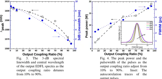
In contrast, the longitudinal mode spacing for the TBPF-free L-band EDFL is slightly enlarged to 3.922 MHz due to the lack of TBFP, while the active mode-locking is achieved at the 262th harmonic of the fundamental longitudinal frequency. Figure 3 shows the 3-dB spectral linewidth and central wavelength of the output spectra from the TROC controlled
EDFL is determined as the output coupling ratio is detuned from 10% to 90%. When the output coupling ratio decreases from 95% to 5%, the L-band ASE absorbs most gain at shorter wavelengths in C-band to facilitate the EDFL lasing at longer wavelength. The wavelength can be tunable from 1565.1 nm to 1605.3 nm, corresponding to a tuning range up to 40.2 nm.
0 10 20 30 40 50 60 70 80 90 100 1560 1570 1580 1590 1600 1610 λ pe a k (n m )
Output Coupling Ratio (%) 0 2 4 6 8 10 3 d B L ine wi dt h ( n m ) 0 10 20 30 40 50 60 70 80 90 100 0 5 10 15 20 -10000 0 10000 0.0 0.2 0.4 0.6 0.8 1.0 In te n s it y ( a .u .) FWHM (fs) 10% 30% 50% 70% 90% R↑
Output Coupling Ratio (%)
P e ak p o wer ( W ) Inte ns it y ( a .u .) FWHM (ps) -10 0 10 0 1 2 3 4 5 6 FW H M ( p s )
Fig. 3. The 3-dB spectral linewidth and central wavelength of the output EDFL spectra as the output coupling ratio detunes from 10% to 90%.
Fig. 4. The peak power and the pulsewidth of the pulses as the output coupling ratio adjust from 10% to 90%. Inset: The autocorrelation traces of the output pulses.
Although the wavelength should be tunable in the whole L-band as the output coupling ratio changes from 0.5% to 99.5%, we failed to monitor and measure the pulse shapes with the sampling oscilloscope or autocorrelator due to their finite sensitivity for the EDFL output at lower output coupling ratios. The autocorrelation traces of the TBPF-free EDFL pulses illustrate that the pulsewidth further shortens as the output coupling ratio decreases, which is mainly due to the broadening of the 3-dB spectral linewidth under an enlarged intra-cavity gain at longer wavelengths. In principle, the mode-locking pulsewidth is directly proportional with(g0)1/4/(δ2⋅fm2⋅Δν2)1/4, where fm denotes the modulation frequency,
Δν represents homogenous linewidth, go is single-pass integrated gain, and δ denotes the
on-to-off modulation depth. The narrowest pulsewidth of 2.4 ps with a largest 3-dB spectral linewidth of 8.2 nm is obtained at 1599.3 nm under a 10% output coupling ratio, providing a time-bandwidth product of 2.35 (Gaussian pulse shape assumed). In addition, the RF spectra of the EDFL pulse measured with a resolution bandwidth of 10 Hz and a frequency span of 10 MHz/div is demonstrated to show the ultrahigh supermode noise suppression ratio (SMSR) of more than 47 dB, as shown in Fig. 5. Such a high SMSR clearly indicates that the amplitude of the output pulses is relatively stable.
998 1000 1002 1004 1006 -110 -100 -90 -80 -70 -60 -50 -40 -30 RBW = 10 Hz VBW = 10 Hz Span =10 Mz Po w e r ( d B m ) Frequency (MHz) supermode supression = 47dB
3.3 Linear Dispersion Compensation of TROC Controlled ML-EDFL Pulses
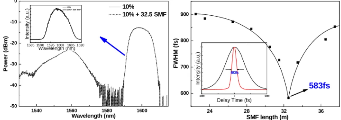
To obtain a narrow pulsewidth with a chirp-free property, a single-mode fiber (SMF) is added after the output port of the L-band ML-EDFL. Because the output pulse is positively chirped, the SMF with a negative β2 is selected to linearly compensate the chirp/dispersion and simultaneously compress the pulsewidth of the TROC controlled EDFL. The unchanged shape of EDFL spectra before and after adding the SMF corroborate that the dispersion compensation is completely linear, as shown in Fig. 6. The shortened ML-EDFL pulsewidth after SMF with a length changing from 22.5 m to 37.5 m is illustrated in Fig. 7. As a result, the narrowest pulsewidth of 580 fs fitted by Gaussian function is obtained after passing the ML-EDFL through a 32.5m-long SMF, giving rise to a time-bandwidth product of 0.56.
1540 1560 1580 1600 -50 -40 -30 -20 -10 0 1585 1590 1595 1600 1605 1610 0.0 0.2 0.4 0.6 0.8 1.0 10% 10% + 32.5 SMF In te n s ity (a .u .) Wavelength (nm) 10% 10% + 32.5 SMF Po we r ( d Bm ) Wavelength (nm) In te n s it y ( a .u .) Wavelength (nm) 1585 1590 1595 1600 1605 1610 24 28 32 36 600 700 800 900 -5000 0 5000 0.0 0.2 0.4 0.6 0.8 1.0 10% 10%+32.5m SMF In te n s ity (a .u .) Delay time (fs) 583fs FW HM ( fs) SMF length (m) 583fs I n ten s it y ( a .u. ) Delay Time (fs)
Fig. 6. The optical spectra of the L-band mode-locked EDFL before and after the SMF based linear chirp compensator.
Fig. 7. Variation of pulsewidth by adding different length of the SMF from 22.5 m to 37.5 m. Inset: The autocorrelation traces of the output pulses before (black curve) and after adding SMF (red curve) at 10% output coupling ratio.
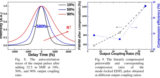
The positive chirp of ML-EDFL pulses is entirely compensated by the anomalous (or negative) group velocity dispersion of SMF in order to slow down the red-shifted leading edge [15], which eventually compresses the ML-EDFL pulsewidth to femtosecond regime. In addition, the optimized linear compression is applied to the EDFL pulses obtained at different output coupling ratios, as shown in Fig. 8. Table 1 shows the wavelength tuning range, the narrowest pulsewidth, and the timing jitter of the L-band ML-EDFL with TBPF, TROC, and after chirp compensation. Although the EDFL with a TBPF has a larger and stable wavelength tuning range, the adding of TBPF inevitably limits the lasing linewidth and thus broadens the pulsewidth of the ML-EDFL. The pulsewidth can be shortened if the TBPF is replaced by the TROC, while the spectral linewidth becomes unlimited in the ML-EDFL. Such a system therefore benefits from not only the simplified wavelength tuning technique but also the cost-effective solution to shorten the output pulsewidth.
-2000 -1000 0 1000 2000 0.0 0.2 0.4 0.6 0.8 1.0 In ten s it y (a.u .) Delay Time (fs) 10% 50% 90% R↑ 580fs 0 20 40 60 80 100 600 800 1000 1200 1400
Output Coupling Ratio (%)
FW HM a fte r c o m p e n s a ti on (fs ) 22 24 26 28 C o m p re ss io n ef fi c ien cy ( % )
Fig. 8. The autocorrelation traces of the output pulses after adding 32.5 m SMF at 10%, 50%, and 90% output coupling ratio.
Fig. 9. The linearly compensated pulsewidth and corresponding compression ratio of the mode-locked EDFL pulse obtained at different output coupling ratios.
3.4 Comparison with Conventional Approaches
Previously, Duan et al. have demonstrated a stable dispersion-tuned harmonic ML-EDFL laser with a wavelength tuning range only from 1555.7 to 1568.1 nm and a pulsewidth of 4 ps by using an intra-cavity semiconductor optical amplifier (SOA) as both a supermode-noise suppressor and a mode locker [3]. Chan et al. proposed an EDFL incorporated with a SOA based nonlinear fiber loop to extend the wavelength tuning from 1542.8 to 1562.3 nm by controlling the delay time between the modulation and the control signals, however, the ML-EDFL pulsewidth as large as 30 ps is limited under such a compensated dispersion-tuning scheme [9]. Zhao et al. also demonstrated a FPLD mode-locked EDFL, covering the wavelength range between 1546.6 and 1551.7 nm by changing the FPLD temperature from 12oC to 19.6 oC [10]. Unfortunately, such a FPLD based mode-locking scheme leads to a broadened pulsewidth of 51 ps. By adjusting an intra-cavity polarization controller to introduce wavelength-dependent cavity loss [13], Feng et al. have demonstrated ultrawide wavelength tunability of 1568.6-1607.8 nm but fails to control the ML-EDFL pulsewidth (~56 ps). In view of previous approaches, the performances of our proposed scheme has already been comparable with those reported by Jeon et al., in which an all-fiber acoustic-optic tunable filter was employed to implement a ML-EDFL with a wavelength tuning range up to 50 nm (1557-1607 nm) and a pulsewidth of 1.5 ps [11]. In comparison with a TBPF controlled wavelength tuning scheme, the propose EDFL does not sacrifice its pulsewidth when providing wavelength tunability. Even without pulse compression, the pulsewidth of the TROC controlled ML-EDFL are already competitive with most of L-band wavelength-tunable EDFL configurations reported previously. In particular, the demonstration of a wavelength tunable L-band EDFL with femtosecond pulsewidth after dispersion compensation is premier.
Table 1. The tuning range, the narrowest pulsewidth, and timing jitter in three different situations.
Experimental setup Tuning Range (nm) Pulsewidth (ps) Jitter (ps)
ML-EDFL with TPBF 45 (1567-1612) 8.8 0.4 ML-EDFL with TROC 2.45
ML-EDFL after compression
40 (1565-1605)
0.58 0.7
4. Conclusions
We have experimentally investigated the femtosecond output performance of a cavity-loss controlled wavelength tunable actively mode-locked EDFL, which is wavelength-tunable in
full L-band without using any intra-cavity TBPF. The wavelength tuning is achieved by adjusting the output coupling ratio of the EDFL with a TROC which introduces wavelength-dependent cavity loss as well as changing the peak of the gain profile. Using a TBPF facilitate a wider tuning range of 45 nm (covering the whole L-band) at a cost of a larger pulsewidth of 14.2 ps. In comparison, the TROC controlled EDFL exhibits a smaller tuning range of 40 nm and a shorter pulsewidth of <5 ps. Under the linear compression in a SMF, we demonstrate the generation of nearly transform-limited Gaussian pulses with a peak power of 17 W and a pulsewidth of 580 fs at repetition rate of 1 GHz. These EDFL pulses are very stable with a side-mode suppressing ratio as high as 47 dB.
Acknowledgments
This work was supported in part by National Science Council under grants NSC 94-2215-E-002-054 and NSC95-2221-E-002-448. Mr. Jun-Yuan Chang was with the Department of Photonics & Institute of Electro-Optical Engineering, National Chiao Tung University, Hsinchu 300, Taiwan R.O.C.