A
Test
Clock
Reduction Method
for Scan-Designed Circuits
t
Jau-Shien Cliang
Chen-Shang Lin
Department, of EJectrical ]Engineering
National Taiwan University
Taipei, Taiwan,
R.1O.C.
Ab st
ractIn this paper, a n o v e l t e s t clock reduction met,hod i s proposed t o generate a c o m p a c t t e s t s c h e m e f o r scan- designed sequential circuits. T h e m e t h o d comprises of t w o phases.
First,
f r o m a g i v e n c o m p a c t combiniution- ab t e s t set, sequential f a u l t propagation is performed after e a c h s c a n - i n operation t o propagate t h e activat- ed f a u l t s and simultaneously detect other undetected f a u l t s a s m a n y a s possible. In t h e second phase, t w o active overlapping t e c h n i q u e s are developedt o
m a x i - m i z e t h e overlap between successive s c a n - i n p a t t e r n s inp u r e s c a n m o d e . T h e experimental results show t h a t t h e n u m b e r of t e s t clocks are reduced t o h a y o,f full- scan. F u r t h e r m o r e , in c o m p a r i s o n w i t h t h e m i x - m o d e t e s t generator, T A R F [ 4 ] requires 54% m o r e t e s t clocks
t h a n ours.
1
Introduction
Scan design is one of the most popular technique of design for testability. The main advantage of scam de- sign is to convert the complicated sequential test prob- lem into the simpler combinational one, and thereby the desirable test quality can be easier to be achieved. On the other hand, significantly lengthened test ,appli- cation time may be incurred by the shifting operations in the long scan chain. Therefore, in the past ;years, various methods have been proposed to reduce test application time of scan-designed circuits[1-9,13]. In this paper, we mainly concern the test time reduction of full scan-designed circuits.
Test time reduction of full scan-designed circuits can be performed either after test generation or during test generation. Test time reduction after test gener- ation has been intensively investigated in [1-3,5,7]. In
[1,2], based on the assumption
that
scan-in and scan- out flip-flops are disjoint, each of the scan-in patternst
This work was supported in part by the National Science Council under contract number NSC-83-0404-E-002055is divided into several segments first. Then, the appli- cation o € a test pattern to the CUT is invoked when a segrnent bul, not a pattern is completely scanned in. Thus, the detection of some faults in response to the later palterns may be occasionally detected by these mixed, (overlapping) patterns. And, the test time can be reduced dum: to the removal of these latter patterns. In [3], the test set is rearranged such that the current conteints of scanned flip-flops can be completely re- used by its next pattern. However, the method may not achieve reduction when the test patterns have lit- tle common parts. More complicate overlapping tech- niques are develioped in [7]. The overlapping of suc- cessive patternis are obtained by precisely controlling the scan in-out operation through the utilization of the don’t caire bits. But, for a given test set with few don’t care bits,, the overlapping will be always corrupted by
a few diiyerent bits in successive patterns. In summa- ry, the effectiveness of these previous works is heavily restricted by the characteristics of the given test set.
To reduce 1,he test application time during test gen- eration ifor scan-designed circuits, the combinational test set can be generated as compact as possible. For test siet compaction, several effective techniques have been developed to generate compacted test sets[6,8-91. However in test application, further reductions on test time can be obtained by carefully rearranging the test patterns. In [3], t e s t generation f o r t e s t application
has been consildered to generate a test set with highly overla.ppling patterns when the scan chain topology is known at priori. However, the penalty of high over- lap is obtained with a larger test set. Unfortunately, sacrificing the compactness of a test set to achieve the overla.pping is not always successful in test time reduc- tion. In [4,13], for sequential circuits with scan capa- bility, a comproimising method, m i x - m o d e t e s t gener- ation, is propo,sed t o generate a compact test applica- tion sequence. The advantage of mix-mode test gener- ation is capable of dynamically switching between scan
and non-scan modes during test generation. Thus, by means of proper mode switching, 100% fault coverage can be obtained through a shorter test sequence. But, for circuits with sequential hard-tedetected or redun- dant faults, the scan operations will occur frequent- ly in test generation and worse results than full-scan may be obtained due t o the lengthy fault propagation sequences in non-scan mode. In [13], some sophisti- cated and time-consuming criterions for mode switch- ing have been proposed. However
,
because generating a compact combinational test set is not considered in non-scan mode, their results are even worse than those of [4].In this paper, t o generate a compact test applica- tion scheme for full scan-designed circuits, a novel test clock reduction method is proposed. The proposed method comprises of two phases. First, based on a compact combinational test set
,
sequential fault prop- agation is performed after each scan-in operation to propagate these activated faults and simultaneously detect the other undetected faults as many as possi- ble in a shorter test sequence than scan-out. When the effectiveness of the above process has decreased below a pre-determined threshold, the next phase will be then invoked. In the second phase, from the com- pact combinational test set for these remaining faults of phase one, two active overlapping techniques, maxi-mum overlapping a n d make-compatible, are developed to maximize the overlapping between the successive scan-in patterns. Different from the previous overlap- ping techniques, the test patterns t o be scanned will be adaptly modified to increase the chance of overlap- ping without sacrificing the overall fault coverage.
The effectiveness of the proposed method are demonstrated by the experimental results on 22 IS- CAS’89 benchmark circuits. On an average, our test clocks are only half of those for full-scan. Further- more, in comparison with the mix-mode test genera- tor, TARF[4] requires 54% more test clocks than our reduction result.
The remaining part of this paper is organized as folisws. The features of the proposed test clock re- duction method and some notations are described in Section 2. Sections 3 introduces the details of maxi- mum overlapping. In section 4, the make-compatible operation will be described. The experimental results are given in section 5. Section 6 gives the conclusions.
2
Test Clock Reduction
In this section, the proposed test clock reduction method will be introduced.
(Combinational)
Scanin j
Scanned Flip-flops
Scan out
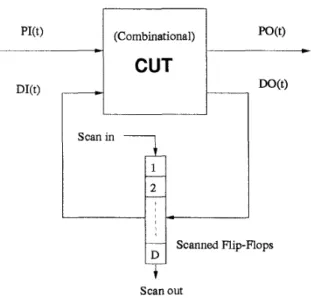
Fig. 1 A scan-designed sequential circuit
2.1
Total Test Clocks
For a full scan-designed circuit as shown in Fig. 1 , each test pattern
t
for the CUT (Circuit Under Test) consists of two parts: the part applied to PI denoted as P l ( t ) and the other part for the FFs (Flip-Flops) as D l ( t ) . In the test application o f t , D l ( t ) must first be shifted into the scan path which generally consists of all FFs in the circuit. Let R E S P ( t ) be the response of CUT after applyingt .
R E S P ( t ) can be similarly divided into PO@) andD O @ ) ,
where P O ( t ) is the response appearing at P O and D O ( t ) is that t o be loaded into FFs. D O ( t ) must also be shifted out of the scan path for observation, which may overlap with the scan-in of the next pattern. Given a fault set Fand a set of patterns P , the detectable faults of P in
F is denoted as D E T ( P , F ) . For a test set T of F and a pattern t E T, the essential faults o f t , denoted as
E S & ( t , F ) , represents the set of faults in F that can only be detected by
t
but not by others in T .Let T be the test set to be applied and
D
be the number of shifts for each pattern (in general, D is the number of scanned flip-flops), then total test time,b ,
is
t T =
(1
TI
+ l ) * D * S + ITI
*C (2.1) where S and C are the periods of a shifting clock and system clock, respectively. Assuming S = C, be- comest T =
((I
T1
+I)
*
D +
I
T
I)
* s
(2.2) The total test clocks ofT
for a scan-designed cir-cuit, TTC, is then
TTC
=(I
T
1
+1)*
D+
1
T
I
(2.3) It can be seen that TTC is dominated byI
TI
and D. Therefore, t o reduce the total test clock, we can either compact the test set T as small as poissible or(and) shorten the number of shifts for each pattern. If
I
T
I>>
1 andD
>>
1, then T T C E /T
I
*D.
In [3], because test generation for test application is con- sidered, the goal of test generation concentrates on how t o increase the overlapping parts among pattern- s but not t o compact the test set. However, it can be seen from the above discussions t h a t , if thr: test size,I
T1,
becomes much larger than the comp,acted one by a certain ratio, then D must be reduced a t least by the same ratio t o keep TTC intact. Unfor- tunately, this is hard t o achieve especially for a CUT with a large number of scanned FFs. Therefore, in our works, the strategy for test clock reduction will s-tart from a compact test set of the CUT, then further reduction processes are proceeded based on the com- pact test set. For test set compaction, currently an effective compaction tool, TSR[6], has been adopted. 2.2 Test Clock Reduction Method
The proposed test clock reduction method is intro- duced in this subsection. The method comprises of two phases. In Phase 1, S c a n and Propagation, from a
compact combinational test set, one scan-in operation followed by fault propagation process is performed it- eratively t o achieve a fault coverage as high as possible in a constrained length of test sequence. In Phase 2,
S c a n and Overlapping, two active overlapping tech-
niques are used t o arrange the test application in pure scan mode as compact as possible.
(1) Phase 1: Scan and Propagation
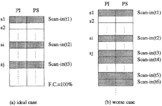
In mix-mode test generation, by means of switch- ing in non-scan and scan mode, an ideal resultant test sequence is shown as Fig. 2(a). In this sequence, some timely scan operations will be incorporated t o enrich the fault coverage of each scan segment and quickly improve the overall fault coverage. A s c a n s e g m e n t
is the clock interval between the first scan-in clocks of a scan-in operation and the next scan-in operation. However, for a CUT with some sequentially h a r d - t e detected or redundant faults, a test sequence ahown as Fig. 2(b) with a lot of scan operations and length- y non-scan sequences could occur. In this case, the number of test clocks will be increased significantly and even greater than
that
by purescan
modeon-
ly. Therefore, the key idea of Phase 1 is t o devise a scheme which retains the nice feature of mix-mode
PI PS s l S can-in(t 1 ) sl Scan-in(t1) s2 s1 Scan-in(t2) si Scan-in(t2) SJ Scan-in(t3) Scan-m(t4) Scan-in(O) Scan-in(t5) S can-in(t6) F.C.=100%
(a) ideal case (b) worse. case.
Fig. 2 Test sequence of mix-mode test generation
test generation without incurring excessively lengthy sequence.
Given a compact combinational test set of the CUT, in Phase 1, the pattern with the largest fault cover- age is chosen for scan-in. After applying this pattern, in addition t o some faults detected at POs, there are other Faults whose effects have been propagated t o FF-
s. For tlhese faults, a propagation process to POs is performed. Tlhe process can be any fault propaga- tion algorithm in sequential ATPG. In this work, a CON'lrEST[11]-like sequential test generator is used for fault propagation and simultaneously detect the other undetected faults as many as possible during propagation. 'To avoid lengthy propagation sequences for some hardly detected faults, the following criterion is used t o decide when t o scan in the next pattern. Scan-In Criterion: T h e s c a n - i n of a n e w p a t t e r n o c c u m w h e n the size of of t h e bast n o n - s c a n s e g m e n t in
t h e t e s t sieque7~1:e is greater t h a n t h e n u m b e r of scanned FFs and n o fivult i s detected in this segment.
The l i d segment without detecting any faults can then be discarded because it does not contribute t o fault ide1,ection. When the fault coverage increases gradually in Phase 1, in general, the scan-in opera- tions will occiir more frequently. However, in a test sequence
,
too inany scan-in operations will cause the previous sequential fault propagation sequences re- dundant and meaningless. To avoid such a situation, the following Stop Criterion is used t o decide when t o stop Phase 1.Stop Criterion: L e t
C,
be t h e n u m b e r of clocks oft h e la5t iscan w g m e n t
Si
and DETs, be t h e n u m b e r of t h e detected f u u l t s inSi.
If
D-T::, < (CYi/D)
*
(I
FI
/
I TI)
(2.4)where
I
FI
i s the size of combinational detectable faults of the CUT,I
TI
i s t h e size of t h e test set f o rF and D i s t h e n u m b e r of the scanned F F s .
Condition (2.4) implies that the effectiveness of fault detection in non-scan mode has fallen below the average detectability of scan mode. In this case, Phase 1 should be stopped and proceeds to Phase 2 which employs scan operation more efficiently.
(2) Phase 2: Scan and Overlapping
In Phase 2, the pure scan mode is adopted to de- tect the remaining faults in Phase l. Starting from a compact test set of these remaining faults, the pattern overlapping techniques are used to arrange the test set such that there are as much overlapping as possible between successive pattern pairs. In this phase, two active overlapping techniques, maximum overlapping and make-compatible, have been developed. In maxi- mum overlapping, the current contents of scanned FFs
are pre-shifted out some signature faulty bits in order
to safely reuse the remaining bits in FFs. The signa- ture faulty bits are the bits at which a given fault set, single stuck-at faults in our case, would manifest the fault effect nearest to the scan-out pins wheil applying the test pattern. Then, successive shifting operations are proceeded t o maximally overlap these remaining bits with the next scan-in pattern. Make-compatible is to enhance the effectiveness of maximum overlap- ping. The blocking bits of the next scan-in pattern for overlapping are modified such that as many bits as possible in FFs can be reused. These two techniques will be described detailedly in the following section. Note t h a t , in this phase, we assume the scan chain topology has been determined.
3
Maximum Overlapping
In this section, the first proposed overlapping tech- nique, M a z i m u m Overlapping, will be introduced.
To reduce the test time, the goal of maximum over- lapping is t o optimally reuse the current contents of
FFs in the next scan-in operation, i.e. to overlap the scan-in and scan-out clocks of two consecutive pat- terns as many as possible. In [3], two special cases for pattern overlapping have been proposed and described as follow. For a pattern t ; and its successive pattern t i f l , if the f a u l t effects of each detectable fault of
ti
can be observed at P O and one of the two cases listed
below is satisfied, then the scan-in operation of
titl
can be completely removed due to the re-use of the current contents of FFs.case (a) complete DO-reuse: D O ( t i ) 3 D I ( t ; + l ) ,
case (b) complete DI-reuse: D l ( t i )
=
D l ( t i + l ) ,where
‘
=’
is the compatible operator. Two vectorsare said to be compatible if all the corresponding bits are either with the same logic value or one of them is
’a’ (don’t care). For example, the two vectors, v l =
(Oa01) and v2 = (OlOz), are compatible and denoted as v l G v2.
From the above description, t o reuse the DO-part or DI-part of
ti,
the pre-condition must be satisfied first, i.e., all the detectable faults o f t can be observedat PO. Thus, even only one detectable fault fails t o be observed at PO, there is no chance of reuse. This is clearly too restrictive. In fact, for the case of DO-
reuse, although some fault effects can not be detected
at PO , if all the signature faulty bits have been pre- shifted out, these remaining bits in FFs can be safely reused. This fact is stated more clear in the following observation and provides a chance to m a z i m a l l y but
not completely reuse the current content of FFs. Observation 1: (Maximum DO-reuse) U n d e r s- ingle fault a s s u m p t i o n , after applying a p a t t e r n t t o the CUT and loading i t s response D O ( t ) i n t o the s- canned F F s , the presence of a detectable f a u l t
f
o f t c a n be determined f r o m either POs or i t s first fault effect bit in D O ( t ) . Furthermore, i f POs and the first fault effect bits of all detectable faults o f t in D O ( t )have been observed t o be fault-free, t h e n these faults are n o t present and D O ( t ) i s t h e fault-free response.
The above observation can be easily justified. For a given detectable fault of a pattern
t ,
its presence in a circuit can be observed from POs or D O ( t ) in which one fault effect bit will be enough. In addition, for all detectable faults, their presence can also be de- termined from POs and one fault effect bit in D O ( t )for each fault. If any of these faults is determined to be present in a circuit, then the circuit is declared faulty and, for testing purpose, no further test applica- tion will be needed. Otherwise, none of the detectable faults
o f t is
present and the responseD O ( t )
must be the fault-free response. The single fault assumption ensuresthat
no fault masking effect can occur.Based on Observation 1, the possible fault effects of each scanned pattern will be analyzed accurately to pre-shift out a certain bits before reuse. To reuse the DO-part of a pattern
t ,
for each fault f detect- ed by t , the possible faulty bit nearest to the scan-out pin is recorded, M I N B I T ( f ) . Then, find the largest M I N B I T ( f ) for all the detected faults: of
t
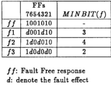
to be the M A X ( M I N B I T ( f ) ) . In such way, even when the pre-condition is not satisfied, the D O ( t ) can be safely reused by shifting out M A X ( M I N B I T ( f ) )bits first. For the example shown in Table 1, suppose
D E T ( { t } , F ) = { f l , f 2 , f3}, D O ( t )
=
(1001010) and the M I N B I T of each fault as listed in M I N B I T (f)
column, the largest M I N B I T ( f ) is found to ’be 4. Therefore, M A X ( M I N B I T ( f ) ) is set t o 4 and D O ( t )
will be shifted out 4 bits before reuse.
f2
1
ldOdOlOI
4f 3
I
ldOdOdOI
2ff: Fault Free response
d : denote the fault effect
Table 1. M A X ( M I N B I T ( f ) ) computation
In the above example, after shifting out DO(:t) = (1001010) by 4 bits, there are still 3 bits remainled in the scanned FFs and D O ( t ) becomes ( z z z t 1 0 0 : ) . To reuse the DO(t) after pre-shifting, patterns not yet ap- plied and compatible with D O ( t ) will be chosen a.s the next scan-in pattern. But, if no pattern is compatible with D O ( t ) , then, a sh$-and-compaTe process is tried t o reuse these remaining bits in D O ( t ) as many as: pos- sible. First, D O ( t ) is shifted out one bit and becomes
( z t t t t 1 0 ) . Then, the comparison of compatibility between D O ( t ) with these remaining patterns will be performed to choose the next scan-in pattern. If it fails, D O ( t ) is shifted out again and the compatibility comparison is performed iteratively. The process will be stopped when a pattern is chosen or all the sipeci- fied bits in D O ( t ) have been shifted out. For the latter case, the pattern not yet applied and with the hilghest fault coverage is chosen as the next scan-in pattern.
For DI-reuse, when the pre-condition is not sat- isfied, the load operation of all FFs must be per- formed. In other words, no partial overlapping with pre-shifting is possible. However, if extra hardwiwe is permitted, the problem of satisfying the pre-cond.ition can be alleviated by improving the observability of CUT such as adding an extra parity output[3].
4
Make-Compatible
In this section, t o enhance the effectiveness of max-
imum overlapping, the second proposed technique,
Make-Compatible, will be introduced. 4.1
Principle
Recall that, maximum overlapping is performed t o optimally reuse the current contents of scanned FFs in the next sciiin-in operation. However, for a test set lacking compatibility between patterns, the reduction on test clock will be insignificant. In other words, the effectiveness of maximum overlapping depends heavily on the characteristics of the given test set. Therefore, t o further enhance the reuse in maximum overlapping, we propose the make-compatible technique which is able t o actively modify the test set for compatibility and increase thie chance of reusage while keeping the overal
I
f a d t coverage intact.The basic idea of make-compatible is based on the over-specification property of the test set t o be s-
canned. For i% test set
T
ofF ,
it is usually unnec-essary to preserve all bits of each pattern in T speci- fied for keeping D E T ( T , F ) intact. For example, for a
CUT
with one PI and four FFs, if T = { t l = (10111),it2 = ( O l l l l ) , t 3 = (10011)) is a test set ofF. For t,he test set T , if tl is the first applied pat- tern and DO(t1) = ( O l O l ) , whatever t 2 or t 3 is cho- sen as the next pattern, it is not possible t o reuse the whole content of FFs. However, if
t 2
can be mod- ified t o i!2’=
(Otlcl) without reducing the overall fault covlerage, then t2’ can be chosen as the next ap- plied pat tern without any shift-in operation becauseDO(t1) ::DI(i-2‘). The modification on t2’ is said to
make compatible with DO(t1). Thus, when choosing the next applied pat tern, make-compatible can be per- formed t o increase the chance of reusage by actively modif2ring these different bits of the next pattern.
In make-cornpatible, the modification on a test pat- tern is to change some bits from ’1’ or ’0’ to ’2’. For
a specified bit of a pattern
t
in a test set T , the bit is said to be raised if its value is changed t o ‘2‘ while keeping the fault coverage of T intact. The preserva- tion of fault coverage is evidently essential. Therefore, to keep the overall fault coverage intact, the following observation is used to guide the raising operation in make-cornpati ble [ 6 ] .Observaition :2: Given a fault set F and a test set
T
of,F,
for a pattern t ET I
if
t
is substituted byt‘
such that DET({t’}, F )2
E S S T ( t , F ) , then T‘ = T - { t } -1{t’}
has at least the same fault coverage as T .The: correctness of Observation 2 can be demon- strated as follow. We have known that
D E T ( T , F ) = D E T ( T , F ) - D E T ( { t } , F )
+
E S S T ( t , F ) ,where I-’ and ’ + I represents the set difference and
set union. Therefore, if E s s T ( t , F )
C
DET({t’},
F ) ,then
D E T ( T , F )
5
D E T ( T , F ) - D E T ( { t } , F )+
D E T ( { t ’ } , F )Thus, T’ = T -
{ t }
+
{t’}
A t least has the same fault coverage as T . To find t‘ such that D E T ( { t ‘ } , F )2
E S S T ( t , F ) is not trivial. Fortunately, in our applica-tion,
t‘
is expected to be obtained from raising some specified bits int
to’d.
Thus, make-compatible can be performed by unspecifying some bits oft
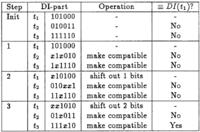
while monitoring the detectability of E S & ( t , F ) by fault simulation. -part 101000 010011 111110 101000 Z l Z O l O l Z l l l 0 Z l O l O O OlOZZl llZll0 Z Z l O l O OlZOll lllZl0 Operation make compatible make compatible shift out 1 bits make compatible make compatible shift out 2 bits make compatible make comuatibleI
+I
Yes Table 2. Example of shift-and-make-compatible Based on Observation 2, the shift-and-compare pro- cess described in maximum overlapping can be refined t o a shij9-and-make-compatible process for achieving more reductions on test clocks. The new process is described by the following example. As shown in Ta- ble 2, for a test set T = { t l , t ~ , t 3 } , after applying t l , shift-and-make-compatible is performed to select the next applied pattern. Only DI-reuse is considered in the example for simplicity. Initially, D l ( t l ) , D l ( t 2 )and D l ( t 3 ) are mutuallyincompatible. In Step 1, after the make-compatible operation on these incompatible bits, the DI-parts of the three patterns are still incom- patible. Therefore, a shift out operation is performed on D l ( t l ) . In step 2, the D I ( t 1 ) is shifted out one bit
first, then make-compatible is performed for D l ( t z )
and D l ( t 3 ) again. Unfortunately, it also fails. Howev- er, in Step 3, after the content of DI(t1) is shifted out two times, the DI-parts of tl and t3 become compatible through make-compatible. Thus, 4 scan clocks can be saved for the scan-in of t3. If only shift-and-compare process is used, there is at most one scan clock which can be saved in this example.
4.2
Phase-2
Algorithm
The detail algorithm of the second phase of test clock reduction with maximum overlapping and make- compatible, is shown in Fig. 3. The algorithm consists of the main routine TCR_Ph2() and the subroutine
maz-overZap().
In T C R P h 2 ( ) , first, the test pattern t with maxi- mum fault coverage is chosen as the first applied pat- tern. To choose the successive pattern of the current applied pattern
t ,
the number of pre-shifts o f t is com- puted by the subroutine M A X - M I N B I T ( t ) . Then, the maximum saved clocks by DO-reuse and the cor- responding successive pattern are obtained by callingm z - o v e r l a p ( ) . However, if the number of pre-shift is zero, the reuse of D I ( t ) becomes possible and the saved clocks are also included to compare with that of DO-reuse. At last, the pattern with the maximal saved clocks with DI-reuse or DO-reuse is chosen as the successive pattern o f t . The process is iterated until the given test set T is exhausted.
In the subroutine, ma c o v erl a p () , the successive pattern
t’
of the current applied patternt
is obtained by searching in the remaining patterns of T such that the saved clocks is largest. The searching process is performed in a greedy way. To find the next patternt’
with largest saved clocks, each time reuse-vector,D I ( t ) or D O ( t ) , is shifted out one bit, and all remain- ing patterns in
T
are tried t o make compatible withreuse-vector. If found, then max-overlap() termi-
nates and the pattern and its saved clocks are record- ed. Otherwise, the reuse-vector is shifted out one more bit and the make-compatible process is repeat- ed. The shifting process will continue until all bits of reuse-vector have been shifted out. If there is no saved clock possible, these remaining patterns in T
with the largest fault coverage will be chosen as the successive pattern.
5
Experimental Results
The proposed two-phase test clock reduction method (ACTIVE) equipped with active overlap- ping techniques, maximum overlapping and make- compatible, has been implemented on SUN4/SPARC2 workstation. To show the effectiveness of our method, 22 benchmark circuits of ISCAS’89 are used as test ex- amples. In the evaluation, the topology of scan-chain is assumed t o be known and is in the natural ordering.
/*
T: the given test set applied to C U T*/
/*
F:
the fault list of C U T*/
/*
next-t: global variable t o store the next scan-in ptrttern TCR-PhB() {*/
choose a t E T with m a x i m u m fault coverage; while ( T is n o t empty) {
T = T - { t } ;
pre-shifts = M A X - M I N B I T ( t ) ;
/*
Compute the saved clocks by DO-reuse DO-save-clk = max-overlap(T, DO(t),pre..shifts) ; DO-next-t = next-t ; load-response = T R U E ; use-DO = T R U E ;/*
T r y DI-reuse*/
i f (pre-shifts == 0) { F = F-DET((t},F);/*
D E T ( t ) can be observed at P O*/
/*
Compute the saved clocks by DI-rewe*/
DLsaue-clk =max-overlap(T, DI(t), pre-shifts) ;
D I - n e x t t = next-t ; if (DI-save-clk
>
DO-save-elk) { loadresponse = F A L S E ; push-test-seq(t,pre-shifts, loadresponse) ; use-DO = F A L S E ; t = DLnext-t ;1
1
i f (use-DO) { push-tes+seq(t,pre-shifts,lwdresponse) ; t = DO-next-t ;1
max-overlap(T, reuse-uector,pre-shzfts) { shift-no = pre-shifts ; while ( s h i f t - n o5
n u m b e r - o f D F F ) { D-content = reuse-vector ; shift_out(D-content,shift-no) ; foreach pattern t' in T { if (make-compatible(D-content,DI(t '),t")) { next-t = t' ; return(no-of-DFF-shift-no) ;1
3
s h i f t - n o i i ;1
choose a t E T with m a x i m u m D E T as next-t ;
return(0) ;
1
[
C
p
v
r
i
1
P O1
SFF
1
SE$-FC%1
#Ps208 1 2 1 8 1 63.72 I 27
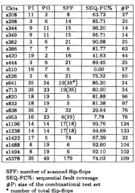
SFF: nurnber of scanned flip-flops
SEQ-FC'& : sequential fault coverage
#I.': size of the combinational test set
*
rtumber of total flip-flopsTable 3. Statistics of ISCAS'89 benchmark circuits In Table 3 , the statistics of these benchmark cir- cuits are showin, including the number of primary in- put
(PI),
primary output(PO), scanned FFs(SFF),
sequential fault coverage (SEQ-FC%) and the combi- national test size (#P). The sequential fault coverage is obtained friom [12]. These combinational test sets are generated by a PODEM-like ATPG and compact- ed by the compaction tool, TSR[6]. Note that, for some circuits in ISCAS'89 benchmark, part of flip- flops are only the output buffers and can be removed from
the
scanned chain. It results in the difference between the number of actually scanned FFs and to- tal FFs for some circuits in Table 3. The results of test clock reduction by ACTIVE are shown in Table 4 and the comparison with previous works is provided in Table 5.In Table 4, the results of ACTIVE on the test clock reduction are shown. The second column, FSCAN, lists the number of test clocks of pure full-scan for the originalcompetcted test sets in Table 3. The ACTIVE- 1 coluimn shotrrr; the results obtained by the first phase
of ACTIVE only, with the Stop Criterion for Phase 1
turned off. In ACTIVE-2 column, the results by the
1
second p'hase of ACTIVE only are shown, i.e., by max- imum overlap Pin€! and make-compatible. The C O m -
plete results oiFACTIVE are shown in the last column. The ratio after. each data is the normalized result with Fig. 3 Algorithm of proposed overlapping techniques
respect t o the result of ACTIVE. ~~ s386 s420 s444
I
AVG1
2.04I
1.36I
1.301
1.01
FSCAN: test clocks needed for pure Full ScanACTIVE-1: mix-mode test generation based on CONTEST A C TIVE-2 : maximum overlapping+make- compat ible ACTIVE: complete results of proposed two-phase method AVG: average ratio w.r.t. the results of ACTIVE
*:
best resultsTable 4. Results of test clock reduction
From Table 4,
it
can be seenthat,
the average test clocks of ACTIVE are only one half of those forpure full-scan (FSCAN) with well-compacted test sets. The resultant test clocks of ACTIVE-1 and ACTIVE- 2 are about 30% larger than ACTIVE but still 70% less than FSCAN. The performance on individual cir- cuit however shows the discrepancy of ACTIVE-1 and ACTIVE-2 while ACTIVE is able to obtain best re- sults in most cases. In Table 4, the best results of 17 out of 22 circuits, marked by
’*’,
are obtained by AC- TIVE, three by ACTIVE-2 and only two by ACTIVE- 1. For these circuits with more scanned FFs and low- er sequential fault coverage such as s838, s1423 and s5378, the results of ACTIVE are far superior to that of ACTIVE-1. This clearly demonstrates the improve- ments of ACTIVE on mix-mode test generation and shows the effectiveness of Stop Criterion described in Section 2. O n the other hand, for those circuits, which are sequentially easily testable and have high sequen- tial fault coverage such as ~ 1 1 9 6 , ~ 1 2 3 8 , s1488 and ~ 1 4 9 4 , ACTIVE clearly outperforms. The fact shows the necessity of combining sequential fault propaga-376j1.39 271 4.4 2.8 7.2
73711.52 485 8.3 5.9 14.2
78811.87 421 16.2 1.8 18.0
tion with scan operations.
The comparisons of ACTIVE with TARF[4], a mix-
mode test generator, are shown in Table 5.
It
can be seen that, except s349, our results are significantly better than those ofTARF.
On the average,TAR-
F needs 54% more test clocks than ACTIVE. Sim- ilar to ACTIVE-1, ACTIVE is especially successful than TARF in those circuits with many scanned FFs and low sequential fault coverage, such as s838 and ~ 1 4 2 3 . Since TARF did not depend on the topology
of scan-chain, the comparison indicates the capability of ACTIVE to exploit the additional information on scan-chain. ~ ~~ s713 s820 s832 s838 I 1.2 I 2.9
I
307 17.1 8.2 25.3 58911.66 354 18.7 8.3 27.0 326312.64 1235 54.2 32.6 86.8 61711.65 375 18.0 10.2 28.2 2.5I
1.2I
3.7 s382 I 680/1.34 I 506 I 14.2 I 1.5 I 15.7 &3* 51196 s1238 924j3.71 249 14.9 6.5 21.4 465/1.13 413 36.6 11.8 48.4 448/1.14 393 46.1 15.6 61.7I
s510i
192‘/1.19i
162i
5.3 I 1.4 I 6.7I
51494 s5378 AV G ~~ I II
s526i
155;/2.02i
7681
17.3I
4.0I
21.3 s641 I 1 314 I 13.6 1 7.6 I 21.2 582/1.59 365 33.7 11.0 44.7 13262 1652.0 242.6 1894.6 1.54 1.0 s1423i
3222/1.851
1746i
200.3i
21.5i
221.8 s1488 1 641/1.79I
358I
32.2I
11.2I
43.4ACTIVE: proposed two-phase method
*:
removed from AVG due to different no. of scanned FFs CPU-time: seconds on SUN4/SPARC2Table 5. Comparison of test clocks of ACTIVE and TARF[4] The CPU-time for ACTIVE is also shown in Table 5. Due t o the complexity of sequential test genera- tion, in comparison with Phase 2, Phase l contributes the dominant part of CPU-time. A practical compro- mise would be to employ Phase 2 only for test clock reduction on larger circuits such as s1423 and s5378.
6
.Conclusions
To minimize test cost for full scan-designed circuit-
s , a novel test clock reduction system, ACTIVE, has
been developed. The proposed method comprises
t-
compact combinational test set, fault effect propaga- tion is performed in non-scan mode after each scan-in operation to detect these sequential easy-to-detected faults. To preserve the compactness of the test set, two criteria, Scan Criterion and Stop Criterion, have been used to decide when t o scan in a new pattern and when t o stop the phase. Phase 1 is proceeded until the effectiveness of fault detection has decreased bellow a
pre-determined threshold. In the second phase, from the compact combinational test set for these rernain- ing faults from phase one, two active overlapping tech- niques, maximum overlapping and make-compatible, have been developed t o maximize the overlapping be- tween successive scan-in patterns. With these: two techniques, the dependency of test clock reduction on the characteristics of original test set can be greatly reduced.
The effectiveness of ACTIVE has been evaluated with 22 ISCAS’89 benchmark circuits. On an ,aver- age, our test clocks are only half of those for full-scan. Furthermore, in comparison with the mix-mode test generator, TARF requires 54% more test clocks than ACTIVE.
References
[l] M. S. Abadir and M. A. Breuer, “Scan Path With Look Ahead Shifting (SPLASH),” Proceedings of 1986 International Test Conference, pp. 696-704. [2] M. S. Abadir, “Efficient Scan Path Testing Using Sliding Parity Response Compaction,” Proceed- ings of 1987 International Test Conference, pp. 332-335.
[3] H. Fujiwara and A. Yamamoto, “Parity-Scan De- sign to Reduce the Cost of Test Application,”
Proceedings o f 1992 International Test Confer- ence, pp. 283-292.
S.
Y.
Lee andK. K.
Saluja, “An Algorithm t o Reduce Test Application Time in Full Scan De- signs,” Proceedings of 1992 ICCAD, pp. 17-20.I. Pomeranz and S. M. Reddy, “A Test Alppli- cation Scheme for Embedded Full-Scan Circuits to Reduce Testing Costs,” Proceedings of .First Asian Test Symposium, pp. 206-211, 1992.
J. S. Chang and C. S. Lin, “Test Set Compaction for Combinational Circuits,” Proceedings of Iyirst Asian Test Symposium, pp. 20-25, 1992.
W. C. Lai, C. P. Kung and C. S. Lin, “Test Time Reduction in Scan Design Circuits,” Proceedings
of 1993 EDAC, pp. 489-498.
[8] GerC-Jan “homp, “Minimal Test Sets for Combi- natiional C‘ircuits,” Proceedings of 1991 Interna- tional Test Conference, pp. 204-209, 1991. [9] I. Pomer(anz, L. N. Reddy and S. M. Reddy,
“COMPACTEST: A Method to Generate Com- pact Test :Sets for Combinational Circuits,’’ Pro- ccedings of I991 International Test Conference,
PI^. 194-203.
[lo]
P.
Goel, “An Implicit Enumeration Algorithm t o Generate Tests for Combinational Logic Circuit-s,” lEEE Trans. on Computers, Vol. C-30, No. 3, Mar. 19831.
[ll] V. D. Agrawal, K. T. Cheng and
P.
Agrawal,” CONTEST: A Concurrent Test Generator for
Sequential Circuits,” Proceedings of 25th Design Automation Conference, 1988, pp. 84-89.
[12]
Wr.
T.
Cheng and S. Davidson, ” Sequential Cir-cuit Test Generator (STG) Benchmark Results,”
Proceedings o f Int. Symp. of Circuits
tY
Systems,1089, pp. 1931-1941.
[13] D.
EL.
Pritidhan and J . Saxena, ” A Design forTestabilit,y Scheme t o Reduce Test Application Timle in Full Scan,” Proceedings of IEEE VLSI
![Table 5. Comparison of test clocks of ACTIVE and TARF[4]](https://thumb-ap.123doks.com/thumbv2/9libinfo/8844643.240079/8.920.503.830.375.791/table-comparison-test-clocks-active-tarf.webp)
