, ~)Pergamon
Printed in Great Britain. All rights reserved 0890-6955/96515.00 + .00o890-69ss(gs)oo076-3
A N E W O N - L I N E S P I N D L E S P E E D R E G U L A T I O N S T R A T E G Y F O R C H A T T E R C O N T R O L
Y. S. LIAOt~ and Y. C. YOUNGt (Received 4 October 1994)
Abstract--A new on-line control method to suppress regenerative chatter vibration during the machining process by regulating spindle speed is proposed. The dynamic cutting force signal collected from a dynamometer is passed through a low pass filter, and then digitized. The fast Fourier transform is carried out to obtain the corresponding power spectrum. The chatter frequency is identified when the intensity at a certain frequency other than the spindle speed and tooth passing frequency exceeds a critical value. Based on the identified chatter frequency, a new spindle speed is computed by applying the principle of keeping the phase between the present and previous undulations to 90 ° . The new speed command is executed while the cutting proceeds. ]It is found from simulation that the chatter vibration can be suppressed by this approach in the shortest time. This method is also verified by experiments through actual cutting of various materials by a computer numerically controlled milling machine. The main feature of this approach is that the feed of the machine tool does not need to be halted during the change of spindle speed. Hence, tool wear can be reduced. Furthermore, no system identification of the machine tool structure is needed, and therefore it has great potential in actual applications.
INTRODUCTION
Chatter vibration, the severe vibration between tool and workpiece under certain cutting conditions, has long been recognized as one of the most significant factors affecting the performance of a machine tool. The occurrence of chatter will result in a decrease of the; metal removal rate and workpiece accuraccy, shortening tool life, and even a reduction of the life of a machine tool. Various attempts, either by active or passive means, have been made over the years to suppress chatter. The active approach included the increase of the rigidity of the machine tool structure by redesign- ing or through the use of dampers, change of tool geometry, variation of directional factors, etc. These approaches usually required a change in the machine tool structure. The second category applies the control theory together with computer technology to suppress chatter. Although it is a passive approach, it has the advantages of low cost and easy implementation. This is particularly appealing for machine tools which have already been constructed.
The chatter control of a turning machine by state feedback control theory [1] and by optimal control theory [2] has been proposed. The displacement signals from a proximeter are fed back to the state estimator, and the instantaneous radial tool position is computed using a computer. The updated command is executed by a tool holder servo-actuator. Although different convergent performance can be obtained, these approaches are only suitable for a time-invariant linear system. There is no guarantee that the approaches will work under complicated non-linear cutting processes and different cutting conditions. Besides, the implementation of these approaches is not practical in actual applications.
Another approach for controlling chatter during the machining process is by regulating the spindle speed of a machine tool. This approach has been studied by several investigators [3-7]. Among them, the spindle speed regulation principle proposed by Smith and co-workers [5, 6] is the most reasonable one due to its theoretically sound background. They suggested that the best tooth passing frequency should be made
tDepartment of Mechanical Engineering, National Taiwan University, Taipei, Taiwan, R.O.C. :~Author to whom correspondence should be addressed.
equal to the system's natural frequency so as to maintain the same variation of cutting depth. Once chatter is detected, the feed of the machine tool is halted while the spindle speed is varied. It is readily clear that the regenerative effect can be eliminated, since after the speed is changed there is no regenerative feedback loop. However, it should be noted that an enormous amount of vibration energy is generated when chatter occurs. By using this approach, the energy already existing in the system is damped out, mainly by the structure's damping effect. Because the machine tool usually has very low damping factors, it will take quite a long time for the vibration amplitude to decay. Hence, when chatter occurs, the feed of the machine tool must be halted immediately to suppress chatter. The holding of feed will accelerate tool wear rate and generate high-pitched noise resulting from the friction between tool and workpiece. In addition, tool marks will be left on the workpiece surface. Chatter waves will always exist in the turning operation since the depth of cut is kept the same. There is also the possibility of inducing process forced vibrations by this approach.
A new on-line spindle speed regulation method to control regenerative chatter is proposed in this paper. The basic principle is to consume chatter energy by the best vibration phase. There is no need to halt the feed during the change of speed, and hence tool life can be maintained and good surface finish can be obtained. Since the computer can monitor the current vibration state and send out new speed command in real time, this control approach can achieve on-line control of the time-varying and non-linear cutting process. Furthermore, since no system identification is needed, the proposed method can be implemented easily on any machine tools without altering any mechanical structure.
T H E O R E ~ C A L BACKGROUND
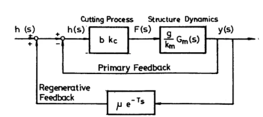
Chatter is the result of interaction between the dynamic cutting process and machine tool structure. Many theories have been proposed to explain the occurrence of chatter [8-10]. Among these theories, regenerative chatter caused by the overlapping cutting of the surface cut previously (in the case of turning, it is the cut one revolution before, and for the milling process it is the cut by the previous cutter) has been considered to be the most important. If the dynamic behavior of the cutting process is neglected, and assuming that the cutting force is proportional to the instantaneous uncut chip thickness, then the regenerative chatter can be simplified by a block diagram, as shown in Fig. 1 [9]. In the figure, ho and h are nominal and instantaneous uncut chip thickness, b is the width of cut, kc is the static cutting stiffness, is, is the overlapping factor and T is the time delay between two consecutive cuts. The dynamics of machine tool structure are represented by
(g/km)Gm (s),
where g is the directional factor and km is the static stiffness of the structure. The characteristic equation of the whole control system can be derived as1 Jr" (1 - -
[]oe-Ts)~mc
G m (s) = 0 ( 1 )h (s) t - "
Cutting Process Structure Dynamics
:*_ h(S)l
IF(S) I g
[ y(s)
'1 bk¢ I
-
l
Primary Feedback Regenerative Feedback • II pe T= !
L_ (n÷o) 2~"
. ,
~ 2 ~ , , " 2 x v , / .-,,,,'~ I - : 1 Yc Surroundings : i - - I',
, " ,
I
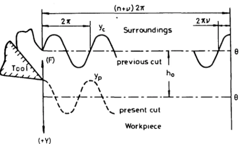
- - v ~ - ~ - - ---4 . . . L _ ~ . t 0 I ~ x _ / ~,~ present cut Workplece (÷Y) or rewritten asFig. 2. Wave-on-wave cutting and phase angle.
gbkc - 1
k--m-- Gm (s) - (1 - l~e-r') " (2)
The time delay between two consecutive cuts causes a phase difference. If there are n + v chatter waves between two consecutive cuts, where n = 0, 1, 2, . . . and 0 - v < 1, then v can be physically explained as the phase difference between the present and previous cuts divided by 2~ (v will be called phase factor in this paper). This is shown schematically in Fig. 2. If the rotational speed is denoted by N, then
1 /
Z N T n + v (3)
where in the above equation Z is the number of cutting edges of the cutter; the values are one for the turning process and two for the drilling process. For the milling operation, it is the total number of teeth of the cutter. Hence, Z N is the tooth passing frequency in the milling process.
Let s = ]~o, then the solution of equation (1) yields the borderline of stability. For a single degree of freedom system (for a machine tool this is reasonable since there is one dominant raode when chatter occurs), the right- and left-hand sides of equation (2) are shown in Fig. 3. The system becomes unstable when there is intersection of
~u :O.B~
;
I I/ '
/ /
°J##l
- I ,..11 ..pe-J2~P I 0.5 1 t a J= 0 Im Re~ ( i b k ~
Stabl
Limit of Stability
e
n s t a b l e
km ~m~ i ~ )
two loci represented by the left- and right-hand sides of equation (2). It is noted that the stability of the system is closely related to the value of v.
For the practical wave-on-wave cutting shown in Fig. 2, let the Y-axis be represented as normal to the cut surface and positive in the downward direction. Assume that the previous cut y¢ and the present cut yp have the same frequency with a phase lag of ~b. Then y¢ and yp c a n be expressed as
yc = Y¢ sin(tot - ~b) = Y~ sin(0 - dp) yp = Yp sintot = Yp sin0.
(4a) (4b)
Assuming that the cutting tool is rigid and perfectly sharp, and it has dynamic displacement according to the variation of cutting force, then the instantaneous uncut chip thickness can be written as
h(0) = yp(0) - yc(0) + ho.
(5)
Neglecting the interference between the flank of the cutting tool and the new work surface just generated, the work done by the vertical component of the cutting force can be expressed as
W = ~ - bk~h(O)
d(yp(O)). (6)The negative sign in the above equation accounts for the direction of the vertical component of the cutting force which always acts upwards. Substituting equations (4a), (4b) and (5) into equation (6) and integrating yields
W(O) = -bk¢ [~ (YpsinO)2 - ypY~ (~ cosdp sin 2
+ hoYp
sinO].1
1
)
0 - ~ 0 s i n ¢ - ~ sind~ sin20 (7)
For one cycle of vibration, 0 is from 0 to 2~, hence
W = -~rbk¢Y~Y r,
sin~b.(8)
When d~ is equal to ~r/2 or equivalently v = 0.25, the largest amount of energy is extracted from the tool-work vibration system in each period, and the system approaches the most stable state. On the contrary, under the condition d~ = -~r/2 (i.e. v = -0.25), the largest amount of energy is generated and entered into the vibration system in each cycle, which causes the system to become unstable. Hence, v = 0.25 is the best phase factor obtained fromt he energy view point. If this phase factor can be maintained in the cutting process, then the largest amount of energy will be dissipated in each vibration cycle, and the system can be brought to the stable state in the least time if the chatter is controllable. It should be noted that by considering the complicated model of a 2D tool vibration together with 1D workpiece vibration, Lee and Liu [11] inferred from time domain and frequency domain simulations that the critical depth of cut is large when the ratio of the workpiece fundamental natural frequency to the spindle speed is approximately equal to n + 0.25, where n = 1, 2, 3, . . . .
CONTROL PRINCIPLE
Based on the discussion given in the previous section, an on-line chatter control strategy is proposed. The signal which is closely related to chatter, such as displacement,
cutting force, acceleration, etc., is collected continuously. In our case the cutting force is selected, since it is easier to measure in the laboratory. The corresponding power spectrum is computed. Once chatter occurs, a high-pitched sound can be heard, and a large intensity at a certain specific frequency other than the spindle speed and tooth passing frequency will appear in the power spectrum. This frequency is identified as chatter frequency f. Substituting chatter frequency f, tooth number Z and v = 0.25 into equation (3), and adjusting n, the modified spindle speed which is closest to the present speed can be obtained. The new speed command is then passed to the computer numerical controller through a computer. While the spindle speed is regulated by the controller, the feed of the table does not need to be stopped since the system has been brought to a new state of dissipating vibration energy.
The only information needed in applying the proposed approach is the chatter frequency. Comparatively, chatter frequency can be identified easily. This is quite different from other approaches which require a complete and accurate model of the system. It should be noted that cutting, combined with the cutting process and structural dynamics, constitutes a complicated time-varying non-linear process, and accurate identification of this system is very difficult, if not impossible. The proposed approach can be easily implemented because the equipment involved is simple and cost effective, and there is no need to alter the machine tool structure. All these features make the proposed approach readily applicable to many machine tools. In addition, because the controller can ~,dapt automatically to the variations in cutting conditions, and provide on-line modified command, good robustness of the controller can be guaranteed.
C O M P U T E R SIMULATION
For the chatter loop shown in Fig. 1, consider a second order machine tool structure system with a ,damping ratio of 0.25, a natural frequency of 30 Hz, g = 1 and
bk¢/
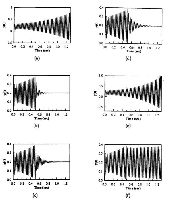
k m = 0.2. In the case of milling, the time-displacement response of the system for a given tooth passing frequency of 19.6 Hz is stimulated and shown in Fig. 4(a). The response diverges with time, and the system is unstable. By carrying out 512-point fast Fourier transformation (FFF), the dominant frequency is found to be 33.2 Hz. Accord- ing to the proposed strategy, if the phase factor v is set to 0.25, then the vibration decays very rapidly, as shown in Fig. 4(b). The responses for v of 0.4 and 0.1 are shown in Figs 4(c) and 4(d), respectively. The variations are almost the same. In both cases the system is stable, but the settling time is apparently longer than that when v is fixed at 0.25. On the contrary, if v is set to 0.75 then, as shown in Fig. 4(e), the time-displacement response diverges, which means that the system remains unstable. From previous ,discussion, when v is set to unity, there is no energy coming in or going out of the system, and the system sustains oscillations, as shown in Fig. 4(f). The vibration energy is dissipated mainly by the structure's damping property. It will take quite a long time for the vibration to reduce to zero because the damping for the machine tool structure is usually very small.
EXPERIMENTAL P R O C E D U R E
The experimental set-up is shown schematically in Fig. 5. The three-phase a.c. motor of the computer numerically controlled milling machine is directly controlled by the inverter (FVR-G5) of a HUST M5 controller. The new speed is computed by an 80386 DX-33 personal computer. The voltage command is sent into the HUST M5 controller via a PCL718 A D D A card to change the spindle speed. The force signal from the dynamometer is amplified and then passed through a low-pass filter before being digitized and intput to the computer.
A slotting process is conducted so that the process can be constrained as a 1D tool-workpiece vibration. The tool used is a four-teeth high speed steel end milling cutter 12 mm in diameter. The work materials are $45C and pure aluminum of size 160 x 140 x 2.'; mm, to conform with the size of the dynamometer.
I 0.5 0 -0.5 0.0 0.2 0.4 0.6 0.8 1.0 1.2 T i m e (sec)
(a)
0.4 0.3~
0.2 0 l 0.0 0.0 ' I m I , I , I 0.2 0 4 0:.6 0.8 1.0 1.2 T i m e (sec) (d) 0.4 0.3~
0.2 0.1 0.0 0.0 I 0.2 0.4 0.6 0.8 Time (sec) (b) , I , I ! .0 1.2|.0
\
0 5 O0 -05 0.0 0,2 04 0.6 0.8 1.0 1,2 Time (see)(e)
0.4 0.3 ,,~ 0.2 0,1 0,0 , I 0,0 0.2 0.4 0.6 0.8 1,0 1.2;""~1~1
I~ II III I I~ VVVV~ -- _ _
, I
Time 0 ~ ) 0.4 0,3 -~0,2 01 0 0 00 0 2 04 0,6 08 10 12 Time (sec)Co)
(0
Fig. 4. Simulation of the placement y(t) for (a) without control, and under control with ( b ) v = 0.25, (c) v = 0.4, (d) v = 0.1, (e) v = 0.75, and (f) v = 1.
estimate the power spectrum of the filtered force signal. When the intensity exceeds a pre-defined threshold, the chatter frequency is identified, and the new speed is computed immediately. The spindle speed motor is driven, otherwise the computer is kept in surveillance state. The sampling rate is selected to be 1000 Hz. For 512-point FFT, the computation time is about 1.2 sec. The experiments have shown that the computer is fast enough to cope with the system response.
In the first experiment, the work material is $45C, the width of cut is 4 mm and the feed is 50 mm/min. The initial spindle speed is 950 rpm. These cutting conditions lie in the unstable region since a high-pitched sound is generated. The corresponding cutting force is shown in part I of Fig. 6(a). The computed power spectrum is shown in Fig. 6(b). It can be seen clearly that there is a large intensity at 150 Hz. After the first control (at the first second), the spindle speed is regulated to 694 rpm. The resultant cutting force is shown in part II of Fig. 6(a), while its power spectrum is shown in Fig. 6(c). Apparently, the intensity at 150 Hz dies out quickly; but, with the
C N C
lling
--7---
,Vci
/ N~XC Drive ~ llachi neDynamoieter
,T1,
C h a r g eAmpl
i fi er m HUST 15 ~ --1~°NCtr°l I
er[ l
/ PCL 71 8 l DI/A J ADC C a r d ~ A / D PC8038 "i~---~
DX-33
I I I " '1Low-pass
Fi l ter
Osci 11 oscopeFig. 5. Experiment setup.
change of system dynamics, another component of 115.2 Hz is excited. After another control by regulating the spindle speed to 531 rpm (at the second second), the high- pitched sound ,disappears. Figure 6(d) shows the power spectrum after the second control has been carded out. As depicted in this figure, the high intensity component becomes very small, and the only components left in the power spectrum are those related to the nominal spindle speed and tooth passing frequency. This can also be seen in part III of the cutting force plot. For comparison, the components due to spindle speed and tooth passing frequency are filtered out from the original cutting force signal, and the resultant signal is shown in Fig. 6(e). The effect of the control can now be visualized more clearly.
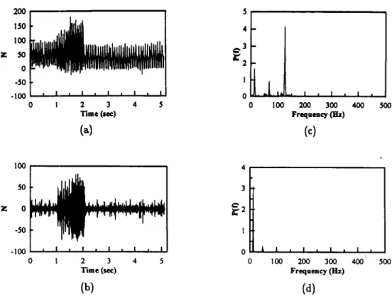
In order to verify the adaptability of the proposed control strategy, the work material is changed to pure aluminum. The width of cut and feed rate are the same as in the first experiment. The initial spindle speed is set to 1000 rpm. The variation of cutting force before and after control is shown in Fig. 7(a), and the filtered cutting force signal is shown in Fig. 7(b). As can be seen from these figures, the system is stable before the first second. The system becomes unstable due to a time-varying property in between the first and second seconds. At this moment, a high-pitched sound is heard which indicates that chatter has occurred. The power spectra before and after control are shown in Figs 7(c) and 7(d), respectively. There is a large intensity at 125 Hz when chatter occurs [Fig. 7(c)]. After the spindle speed is regulated to 833.3 rpm, the high-pitched sound disappears, and consequently the component of 125 Hz in the power spectrum is also suppressed [Fig. 7(d)].
DISCUSSION
The dynamics of the tool-work system during the cutting process can be affected by the spindle ,.speed. Hence, while speed regulation can suppress chatter caused by the identified chatter frequency, it may excite another frequency such as that depicted in the first experiment given in the previous section. Nevertheless, when this situation occurs, it is found that regulation of speed twice will usually be enough to bring the system to the stable state.
According to equation (3), the speed can be either increased or decreased when the spindle speed is. regulated for the purpose of suppressing chatter. In the experiments
500 400 300 Z 200 I00 0 -100 I , , I , I . I , 1 0 2 3 4 T i m e ( s e e ) 4 2 0 0 ., U 100 , I , I , I 200 300 400 Frequency (Hz)
(a)
500 2 0 0 J Id h , I 0 I O0 200 300 Frequency OH[z)(b)
, I , 400 500 Z 200 100 0 -100 -200 0 1 2 3 Time ( s e e )l
2 0 0 100 200 300 400 500 F r e q u e n c y (ILl)Fig. 6. Milling of $ 4 5 C ( a ) force signal I, ( b ) power spectrum of part I signal, (c) power spectrum of part I I s i g n a l , ( d ) power spectrum of part III signal, and ( e ) filtered force signal.
shown in the previous section, the speed is reduced when chatter occurs. This is because the machine tool and cutting tool used in the experiment limited the spindle speed to run no higher than 1000 rpm. By applying the proposed method to other machines, the initial speed can be set to any value within the capacity of the installed motor of the machine tool.
There are two cases where the stable speed may not be found. Evidently, if too large a width of cut which exceeds the stability limit is employed, the system cannot be brought to the stable state by regulating the spindle speed. Secondly, if the system has multiple modes and the stability lobes of different modes are located as those shown in Fig. 8, the region above the critical width of cut is almost the unstable cutting condition region. However, this coincidence is extremely rare.
A similar approach of regulating spindle speed proposed by Smith and co-workers [5, 6] required the feed to be halted during the change of spindle speed. If the feed is halted during the cutting process, a high-pitched sound will be generated, and it has a negative effect on tool wear. Figure 9 is a typical sound record when the feed is halted arbitrarily during the cutting process. The larger amplitude corresponds to the moment when the feed is held still.
=¢ 200 150 100 50 0 -50 -100 0 i l I I i l I 2 3 4 5 Tim® (see)
(a)
~ 3~2
'
/ 1
0 _ ~ i - ! , ! f I 0 I00 200 300 400 F r e q u e n c y (E[z)(c)
I 500 100 50 0 -50 -100 0 43 I
! 0 I I I I I I , I * I , I = 1 2 3 4 5 0 1 O0 200 300 400Time (see) Frequency (BIz)
(b) (d)
500
Fig. 7. Milling of aluminum (a) force signal, (b) filtered force signal, (c) power spectrum before control, and (d) power spectrum after control.
model
o, oo,
I \
I\REGI'ONI
V ~%/%/%, %
STABLE REGION =
N ~
Fig. 8. Stability lobes for an extreme case of two-modes system.
m 100
"O
0 0.5 I 1.5 2 2.5 3 3.5 Time (see)
Fig. 9. Sound record when the feed is halted during milling process,
C O N C L U S I O N
A new spindle speed regulation approach to on-line control of self-excited regenerat- ive chatter vibration during the machining process is proposed. Simulation and actual cutting experiments have shown that the vibration energy can be dissipated rapidly, and the system can be brought to stable state by forcing the vibration phase to 90 ° .
One particular feature of this approach is that the change of speed can be carried out without the need to halt the feed of the table. In this way, good workpiece surface finish can be obtained, and tool wear rate will not be accelerated. In applying the proposed approach, there is no need to identify the whole system, besides detection of the dominant frequency. Furthermore, it is very easy to implement the proposed strategy. There is no need to alter any part of the machine tool structure. Hence, it has great potential for practical applications.
REFERENCES
[1] M. Shiraishi and E. Kume, Ann. C1RP 37, 369-372 (1988).
[2] M. Shiraishi, K. Yamanaka and H. Fujita, Int. J. Mach. Tools Manufact. 31, 31-43 (1991).
[3] K. F. Eman and S. M. Wu, A S M E Publ. PED 2, 37-52 (1980).
[4] S. Y. Tsai, K. F. Eman and S. M. Wu, Proc. llth N A M R C , 339-402 (1993).
[5] S. Smith and J. Tlusty, Ann. C1RP 41, 433-436 (1992).
[6] S. Smith and T. Delio, J. Engng Ind. 114, 486-492 (1992).
[7] S. C. Lin and M. R. Hu, Int. J. Mach. Tools Manufact. 32, 629-540 (1992).
[8] S. A. Tobias, Machine Tool Vibration. Blackie & Son, Glasgow (1965).
[9] H. E. Merrit, J. Engng Ind. 87, 447-454 (1965).
[10] F. Koenigsberger and J. Tlusty, Machine Tool Structure, Vol. I. Pergamon Press, Oxford (1971).