Intermetallic Reactions in Sn3Ag0.5Cu and
Sn3Ag0.5Cu0.06Ni0.01Ge Solder BGA Packages
with Au/Ni Surface Finishes
T.H. CHUANG,1,2S.F. YEN,1and M.D. CHENG1
1.—Institute of Materials Science and Engineering, National Taiwan University, Taipei 106, Taiwan. 2.—E-mail: [email protected]
The intermetallic compounds (IMCs) formed during the reflow and aging of Sn3Ag0.5Cu and Sn3Ag0.5Cu0.06Ni0.01Ge solder BGA packages with Au/Ni surface finishes were investigated. After reflow, the thickness of (Cu, Ni, Au)6Sn5interfacial IMCs in Sn3Ag0.5Cu0.06Ni0.01Ge was similar to that in the Sn3Ag0.5Cu specimen. The interiors of the solder balls in both packages contained Ag3Sn precipitates and brick-shaped AuSn4 IMCs. After aging at 150°C, the growth thickness of the interfacial (Ni, Cu, Au)3Sn4 intermetallic layers and the consumption of the Ni surface-finished layer on Cu the pads in Sn3Ag0.5Cu0.06Ni0.01Ge solder joints were both slightly less than those in Sn3Ag0.5Cu. In addition, a coarsening phenomenon for AuSn4IMCs could be observed in the solder matrix of Sn3Ag0.5Cu, yet this phenomenon did not occur in the case of Sn3Ag0.5Cu0.06Ni0.01Ge. Ball shear tests revealed that the reflowed Sn3Ag0.5Cu0.06Ni0.01Ge packages possessed bonding strengths similar to those of the Sn3Ag0.5Cu. However, aging treatment caused the ball shear strength in the Sn3Ag0.5Cu packages to degrade more than that in the Sn3Ag0.5Cu0.06Ni0.01Ge packages.
Key words: Sn3Ag0.5Cu, Sn3Ag0.5Cu0.06Ni0.01Ge, Au/Ni surface finishes, ball-grid-array package, intermetallic compounds
INTRODUCTION
The eutectic Sn-Ag-Cu alloy system has been con-sidered to be the most promising candidate to re-place traditional Sn-37Pb solders for environmental reasons.1 A Sn-Ag-Cu ternary solder has been al-loyed with a trace amount of Ni in order to further improve its mechanical strength and wettability.2In addition, microalloying with Ge reveals the benefi-cial effects of better mechanical properties and lower dross formation.3 However, Chuang and Lin have reported that the dipping of Cu plates into a Sn-3.5Ag-0.5Cu-0.07Ni-0.01Ge solder at 250°C for 15 sec results in interfacial (Cu, Ni)6Sn5 intermetallic compounds (IMCs) much thicker than are obtained by dipping into a liquid Sn-3.5Ag-0.7Cu solder.4–6 Through further aging of the specimens at various temperatures from 105 to 150°C, they have found that those thicker intermetallic layers in
Sn-3.5Ag-0.5Cu-0.07Ni-0.01Ge solder joints possess a slower growth rate than that for undoped Sn-3.5Ag-0.5Cu. Chuang and Lin also studied the intermetallic reac-tions in reflowed and aged BGA packages with Sn3.5Ag0.5Cu and Sn3.5Ag0.5Cu0.07Ni0.01Ge sol-der balls on Au/Ni/Cu pads.4–6Three types of inter-metallic phases have been observed: plate-like Ag3Sn, lump-shaped (Cu, Ni)6Sn5, and thin-layer (Ni, Cu)3Sn4, and, for both solder alloys, the mor-phologies and total thicknesses of interfacial inter-metallics are similar. In addition, aging treatments have not been shown to cause the intermetallic lay-ers in both solder BGA packages to grow. These re-sults were explained by Chuang and Lin: the (Ni, Cu)3Sn4 acts as a diffusion barrier to retard the in-terdiffusion of Sn and Cu.6
In our previous study on the interfacial reactions in BGA packages with an immersion Ag surface fin-ish, scallop-shaped Cu6Sn5 IMCs and a continuous (Cu, Ni)6Sn5intermetallic layer have been observed in reflowed Sn3Ag0.5Cu and Sn3Ag0.5Cu0.06Ni0.01Ge (Received June 28, 2005; accepted October 17, 2005)
solder joints, respectively.7The interfacial interme-tallics in both solder joints possess similar thick-nesses. However, a thick Cu3Sn intermetallic layer with a large number of Kirkendall voids appears at the interface between the Cu6Sn5 intermetallic scallops and the Cu pads in the Sn3Ag0.5Cu speci-mens after aging at 125 and 150°C. The formation of such a Cu3Sn intermetallic layer with Kirken-dall voids has been effectively inhibited in the aged
Sn3Ag0.5Cu0.06Ni0.01Ge solder joints. In this present study, the effects of Ni addition on the in-termetallic reactions of the reflowed and aged Sn-Ag-Cu solder BGA packages with Au/Ni/Cu pads were further investigated.
EXPERIMENTAL PROCEDURES The geometry of the ball-grid-array (BGA) pack-ages with Au/Ni surface finishes used in this study was shown in a prior work.8The Si die was attached to a bismaleimide triazine (BT) resin substrate and encapsulated with molding compound. Each pack-age was fitted with 49 Cu pads electroplated with 5-m-thick Ni and immersion plated with 0.5-m-thick Au. The 0.4-mm diameter Sn3Ag0.5Cu and Sn3Ag0.5Cu0.06Ni0.01Ge (wt.%) solder balls were dipped in rosin mildly activated (RMA) flux, placed on the Au/Ni/Cu pads, and then reflowed in a hot-air furnace equipped with five heating zones. The reflow temperature profile is shown in Fig. 1, where the soaking temperature and peak tempera-ture were set at 190 and 240°C, respectively. Cer-tain reflowed BGA packages were further aged at 100 and 150°C for various times ranging from 100 to 1000 hr.
The reflowed and aged specimens were cross sec-tioned through a row of solder balls, ground with Fig. 1. Temperature profile for the reflowing process of the
Sn-Ag-Cu solder BGA packages with Au/Ni/Sn-Ag-Cu pads in this study.
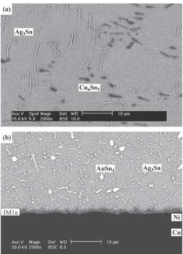
Fig. 2. Microstructure of the Sn3Ag0.5Cu solder balls before reflow-ing (a) and after reflowreflow-ing (b) on Au/Ni/Cu pads of BGA packages.
Fig. 3. Microstructure of the Sn3Ag0.5Cu0.06Ni0.01Ge solder balls before reflowing (a) and after reflowing (b) on Au/Ni/Cu pads of BGA packages.
2000-grit SiC paper, and polished with 0.3-m Al2O3 powder. The IMCs were observed via scanning elec-tron microscopy (SEM), and their chemical compo-sitions were analyzed using an energy-dispersive x-ray spectrometer (EDX) installed in the SEM. For kinetic analysis, the maximum growth distances of convex scallops for each intermetallic layer were measured. The average value of a minimum of 30 measurements for each soldering condition (per re-action temperature and time) was determined to sig-nify the intermetallic thickness (X).
The bonding strengths of the solder balls on the Au/Ni/Cu pads under reflow and various aging con-ditions were measured via ball shear tests. For this purpose, the ball shear rate was fixed at 0.1 mm/sec with a shear height of 80m (about1⁄4the reflowed
ball height). An average value was taken from 49 measurements on each package. After the ball shear tests, the fractography of the fractured solder joints was observed with the SEM.
RESULTS AND DISCUSSION
The microstructure of Sn3Ag0.5Cu solder balls before reflow contained needle-shaped Ag3Sn and cluster-shaped Cu6Sn5 IMCs, as shown in Fig. 2a. Figure 2b reveals that, after reflow, the needle-shaped Ag3Sn precipitates resolidified into fine
par-ticles, while a (Cu0.55Ni0.40Au0.056Sn5
intermetal-lic layer (IM1a) formed at the solder/pad inter-face. This is evidence that the Ni surface finished layer on the Cu pad can attract the dissolved Cu atoms from the Cu6Sn5clusters in the solder matrix to the solder/Ni interface. In addition, a large amount of coarse AuSn4 intermetallic bricks have appeared in the solder matrix. These AuSn4 inter-metallics are derived from the rapid dissolution of the Au film on the Ni/Cu pads during reflow and the ensuing reaction with the liquid Sn3Ag0.5Cu solder.
Before reflow, the Sn3Ag0.5Cu0.06Ni0.01Ge sol-der balls possessed a microstructure similar to that of Sn3Ag0.5Cu, which is revealed in Fig. 3a. How-ever, Fig. 3b shows that, after reflow, the coarse brick-shaped AuSn4 intermetallics found in the Sn3Ag0.5Cu0.06Ni0.01Ge solder matrix are of a much smaller quantity than those in the reflowed Sn3Ag0.5Cu. In contrast, the AuSn4 intermetallic phase in this Ni doped Sn-Ag-Cu solder appeared as flake-shaped. The needle-shaped Ag3Sn precipitates have also resolidified into particles slightly larger in size than is the case for the reflowed Sn3Ag0.5Cu solder joints. The interfacial intermetallics in the reflowed Sn3Ag0.5Cu0.06Ni0.01Ge BGA package have a composition of (Cu0.64Ni0.34Au0.02)6Sn5
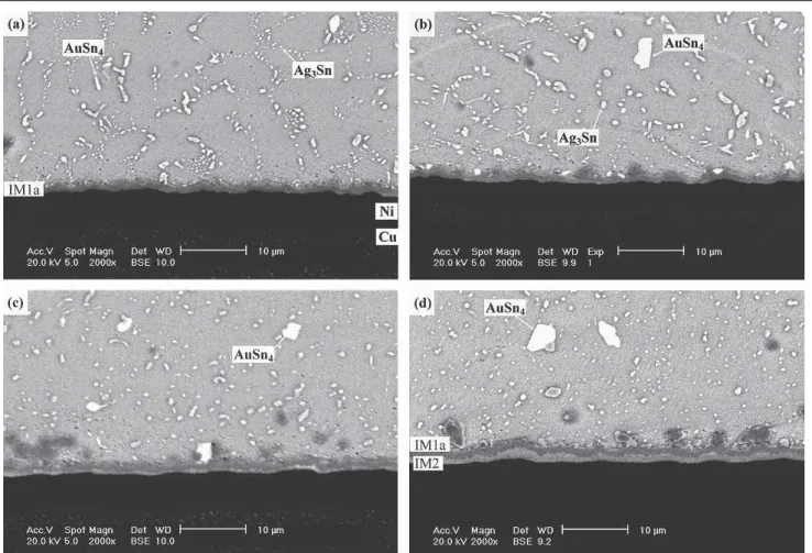
Fig. 4. Morphology of intermetallic compounds formed at the interfaces of the Sn3Ag0.5Cu solder joints on Au/Ni/Cu pads after aging at 100°C for various times periods: (a) 100 hr, (b) 300 hr, (c) 700 hr and (d) 1000 hr.
(IM1b), and their thickness is similar to that of the Sn3Ag0.5Cu specimen.
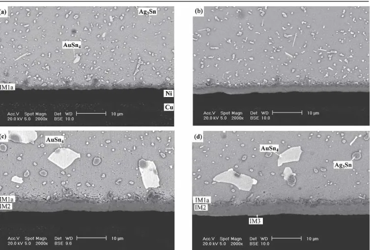
The Ag3Sn particles are seen to have coarsened from the aging of the Sn3Ag0.5Cu solder joints at 100°C, as shown in Fig. 4. A certain number of AuSn4intermetallic compounds in the solder matrix are also found to have grown abnormally to a rela-tively large size with increased aging time. How-ever, the (Cu0.50Ni0.40Au0.05)6Sn5intermetallic layer (IM1a) at the solder/pad interface exhibits only slight growth. After prolonged aging for over 700 hr, an extra intermetallic layer appears between the IM1a intermetallics and Ni/Cu pad. EDX analysis indicates that the composition of this new interme-tallics layer is (Cu0.50Ni0.42Au0.08)6Sn5(IM2), with a Au content higher than IM1a.After aging at 150°C for over 700 hr, the intermetallic layer IM2 can be seen to have grown thicker, accompanied by the ap-pearance of many gigantic AuSn4 intermetallics in the solder matrix, as shown in Fig. 5. Furthermore, a new intermetallic layer is formed at the interface between the IM2 intermetallic layer and the Ni sur-face finish. EDX analysis identifies the composition (at.%) of the newly-appeared intermetallic com-pound as Ni:Cu:Au:Sn ⳱ 37.16:4.98:0.54:57.32, which corresponds to the (Ni0.87Cu0.12Au0.01)3Sn4 phase (IM3). The appearance of such a (Ni, Cu,
Au)3Sn4 interfacial intermetallic layer (IM3) is re-vealed in Fig. 6 at larger magnification. In contrast, the continuous IM1a intermetallic layer has become thinner and become scallop-shaped with the in-crease of aging time.
For the Sn3Ag0.5Cu0.06Ni0.01Ge BGA packages, the morphology of the intermetallics in the solder matrix after aging at 100 and 150°C is quite differ-ent from what has been observed with the Sn3Ag0.5Cu specimens. Figures 7 and 8 show that the Ag3Sn precipitates and AuSn4 intermetallic compounds in the Sn3Ag0.5Cu0.06Ni0.01Ge are very slow in coarsening. Moreover, no gigantic AuSn4 intermetallics are to be found in the solder matrix of the Sn3Ag0.5Cu0.06Ni0.01Ge, though they have appeared in the Sn3Ag0.5Cu packages (Fig. 5). The inhibition of Ag3Sn and AuSn4 coars-ening for Sn3Ag0.5Cu0.06Ni0.01Ge might be attrib-uted to the Ni elements in this solder alloy acting as nucleation sites, which leads to a dispersing effect of Ag3Sn precipitates and AuSn4 intermetallics. Fig-ure 7 also shows that the thickness of the interfacial IM1b intermetallic layer remains unchanged as the aging time increases. After aging at 100°C, there is no trace of the IM2 intermetallic layer with high Au content in the Sn3Ag0.5Cu0.06Ni0.01Ge, which nevertheless has been observed at the IM1a/Ni
in-Fig. 5. Morphology of intermetallic compounds formed at the interfaces of the Sn3Ag0.5Cu solder joints on Au/Ni/Cu pads after aging at 150°C for various times periods: (a) 100 hr, (b) 300 hr, (c) 700 hr and (d) 1000 hr.
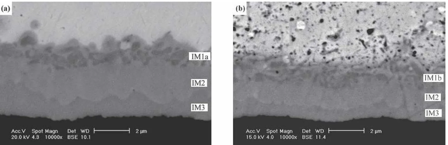
terface of the Sn3Ag0.5Cu solder joints (Fig. 4). The interfacial IM2 intermetallic layer cannot be seen in the Sn3Ag0.5Cu0.06Ni0.01Ge until the aging tem-perature is increased to 150°C, as shown in Fig. 8. Prolonged aging at 150°C for 1000 hr can also cause the formation of a (Ni0.87Cu0.12Au0.01)3Sn4 interme-tallic layer (IM3) at the interface between the IM2 intermetallics and the Ni surface finish (see Figs. 6b and 8d). However, the growth of IM2 and IM3
inter-metallic layers in Sn3Ag0.5Cu0.06Ni0.01Ge solder joints is slower than that of Sn3Ag0.5Cu.
For comparison, the thicknesses of interfacial in-termetallic layers IM2 and IM3 in both solders after aging at 100 and 150°C were measured and plotted in Fig. 9a and b, respectively. Because the IM1a in-termetallic layer was observed in Fig. 9c to diminish with the growing of the IM3 intermetallic layer, the residual thickness of the Ni surface finishes during Fig. 6. Morphology of intermetallic compounds formed at the interfaces Sn3Ag0.5Cu (a) and Sn3Ag0.5Cu0.06Ni0.01Ge (b) solder joints on Au/Ni/Cu pads after aging at 150°C for 700 hr with a larger magnification.
Fig. 7. Morphology of intermetallic compounds formed at the interfaces of the Sn3Ag0.5Cu0.06Ni0.01Ge solder joints on Au/Ni/Cu pads after aging at 100°C for various times periods: (a) 100 hr, (b) 300 hr, (c) 700 hr and (d) 1000 hr.
the interfacial intermetallic reactions was also mea-sured and plotted in Fig. 9d. It is evident that the growth thickness of IM2 and IM3 intermetallic lay-ers and the consumption of the Ni surface finishes in Sn3Ag0.5Cu0.06Ni0.01Ge are both slightly less than those in the Sn3Ag0.5Cu packages.
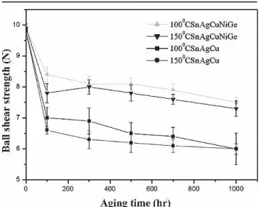
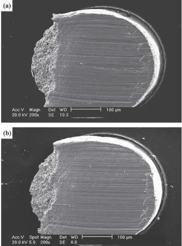
The bonding strengths of the solder joints were measured via ball shear tests and listed in Table I and Fig. 10. The results indicate that the as-re-flowed Sn3Ag0.5Cu and Sn3Ag0.5Cu0.06Ni0.01Ge solder BGA packages with Au/Ni/Cu pads pos-sess very similar ball shear strengths at 9.8 and 9.9 N, respectively. After aging at 100 and 150°C, the b o n d i n g s t r e n g t h s o f t h e S n 3 A g 0 . 5 C u a n d Sn3Ag0.5Cu0.06Ni0.01Ge solder joints have de-creased to about 6.3 ± 0.5 and 8.0 ± 0.4 N, respec-tively. It is evidenced that the bonding strength of the Sn3Ag0.5Cu0.06Ni0.01Ge solder joints has de-graded by about 19% due to the aging treatment, which is less than the amount of degradation for Sn3Ag0.5Cu (36%). Fractography of all specimens after ball shear tests reveals the ductility across the solder balls (Fig. 11); therefore, as compared to the case of Sn3Ag0.5Cu0.06Ni0.01Ge, the much higher degradation rate of the bonding shear strengths for aged Sn3Ag0.5Cu solder joints should be attributed
to the greater softening tendency of the solder ma-trix which has arisen from the stronger coarsening effect of those Ag3Sn precipitates and AuSn4 inter-metallics in Sn3Ag0.5Cu.
CONCLUSIONS
The element Ni, in trace amounts, has been added to the ternary eutectic Sn3Ag0.5Cu solder alloy for the purpose of improving its mechanical strength and wettability.2This present study showed that the addition of Ni could also render distinct effects on the intermetallic reactions in those Sn-Ag-Cu BGA packages with Au/Ni surface finishes. Experimental re-sults revealed that continuous (Cu0.55Ni0.40Au0.05)6Sn5 and (Cu0.64Ni0.34Au0.02)6Sn5 intermetallic layers (IM1a and IM1b) were formed at the solder/pad in-t e r f a c e s o f in-t h e r e f l o w e d S n 3 A g 0 . 5 C u a n d Sn3Ag0.5Cu0.06Ni0.01Ge solder joints, respec-tively. In addition, Ag3Sn precipitates and AuSn4 intermetallics appeared in the as-reflowed solder matrices of both packages. Aging at 100 and 150°C caused the Ag3Sn and AuSn4in the Sn3Ag0.5Cu sol-der joints to grow rapidly. The AuSn4intermetallics even became gigantic in the Sn3Ag0.5Cu solder BGA packages. On the other hand, the coarsening of Fig. 8. Morphology of intermetallic compounds formed at the interfaces of the Sn3Ag0.5Cu0.06Ni0.01Ge solder joints on Au/Ni/Cu pads after aging at 150°C for various times periods: (a) 100 hr, (b) 300 hr, (c) 700 hr and (d) 1000 hr.
Ag3Sn precipitates was much slower, and the forma-tion of gigantic AuSn4intermetallics was inhibited in the aged Sn3Ag0.5Cu0.06Ni0.01Ge specimens. Dur-ing the agDur-ing process, an extra (Cu0.50Ni0.42Au0.08)6Sn5 intermetallic layer (IM2) with higher Au content ap-peared at the IM1a/Ni and IM1b/Ni interfaces. After
F i g . 1 0 . B a l l s h e a r s t r e n g t h s o f S n 3 A g 0 . 5 C u a n d Sn3Ag0.5Cu0.06Ni0.01Ge solder BGA packages with Au/Ni/Cu pads after aging at 100°C and 150°C for various time periods. Fig. 9. The growth thicknesses (X) of interfacial (a) IM2 (b) IM3 (c) IM1a and IM1b intermetallic layer and (d) the residual thickness (XNi) of Ni surface finishes in Sn3Ag0.5Cu and Sn3Ag0.5Cu0.06Ni0.01Ge solder BGA packages after aging at 100°C and 150°C versus the aging time (t).
Table I. Ball Shear Strengths (N) of Sn3Ag0.5Cu and Sn3Ag0.5Cu0.06Ni0.01Ge BGA Packages with
Au/Ni/Cu Pads After Aging at 100 and 150°C for Various Time Periods
Aging Time (hr) Sn3Ag0.5Cu Sn3Ag0.5Cu0.06Ni0.01Ge 100 150 100 150 As reflowed 9.8 9.8 9.9 9.9 100 7.0 6.6 8.4 7.8 300 6.9 6.3 8.1 8.0 500 6.5 6.2 8.1 7.8 700 6.4 6.1 7.9 7.6 1000 6.0 6.0 7.5 7.3
prolonged aging, the continuous IM1a intermetallic layer diminished and became scallop shaped, allow-ing for the appearance of a (Ni0.87Cu0.12Au0.01)3Sn4 intermetallic layer (IM3) at the IM2/Ni interface. The results also indicated that the growth thick-nesses of both interfacial IM2 and IM3 intermetallic layers in Sn3Ag0.5Cu0.06Ni0.01Ge packages were lower than those for Sn3Ag0.5Cu packages. Aging treatments resulted in the softening of the solder matrix, which in turn led to the degradation of ball s h e a r s t r e n g t h s i n t h e S n 3 A g 0 . 5 C u a n d Sn3Ag0.5Cu0.06Ni0.01Ge packages from 9.8 and 9.9 N (reflowed state) to about 6.3 and 8.0 (aged state), respectively.
ACKNOWLEDGEMENT
The authors sincerely thank the National Science Council, Taiwan, for sponsoring this research (grant NSC-93-2216-E002-024).
REFERENCES
1. K. Zeng and K.N. Tu, Mater. Sci. Eng. R 38, 55 (2002). 2. M. Yamashita, S. Tada, K. Shiokawa, and Fuzi Electric Co.,
“Solder Alloys,” U.S. patent 6,179,935 B1 (2001).
3. K. Habu, N. Takeda, H. Watanabe, H. Ooki, J. Abe, T. Saito, Y. Taniguchi, and K. Takayama, Proc. Int. Conf. Electron.
Environment, (New York: IEEE, 1999), p. 21.
4. C.M. Chuang and K.L. Lin, J. Electron. Mater. 33, 1426 (2003).
5. C.M. Chuang, P.C. Shi, and K.L. Lin, 2002 Int. Symp.
Elec-tron. Mater. Packag., IEEE, 360 (2002).
6. C.M. Chuang, P.C. Shi, and K.L. Lin, Proc. Int. Conf.
Elec-tron. Mater. Packag., (New York: IEEE, 2002), p. 360.
7. S.F. Yen, H.M. Wu, and T.H. Chuang, J. Electron. Mater. 35, 310 (2005).
8. T.H. Chuang, S.Y. Chang, L.C. Tsao, W.P. Weng, and H.M. Wu, J. Electron. Mater. 32, 195 (2003).
Fig. 11. Typical Fractography of the (a) Sn3Ag0.5Cu and (b) Sn3Ag0.5Cu0.06Ni0.01Ge solder joints in BGA packages after ball shear tests.