雙球面鏡之多次再入射環型共振腔雷射之研究及應用
185
0
0
全文
(2) 誌謝 人的一生當中好像總會面臨許多意想不到的事,進中山大學光電所碩 士班也是其中之一。很幸運的黃升龍博士是我的指導教授,我非常喜歡跟 黃老師做實驗,因為很有挑戰性,雖然在知識上常常受到從黃老師方面來 的挫折,可是我覺得自己非常幸運可以有機會激發出自己的某一個潛能。 我真的非常感謝黃老師。 在中山六年要謝謝的人非常多,光電所的鄭木海、陳永光及朱安國教 授,碩士班時的學長、同學,博士班後的學弟妹們;不只是研究方面的, 更重要的是我可以從不同的人身上試著以他們的角度看事情,學會體諒與 包容。蘇景弘同學在程式上幫了我許多忙,康志聰、莊泰斌及葉靜宜小姐 也都對我非常照顧;鄭慧如博士不僅在研究上多次啟發我,在生活哲學上 更是給了我許多寶貴的意見和幫助。也要感謝工研院賀方涓博士給我機會 接收磨練,學習鍍膜的技術,柳昀呈、侯文正、黃承揚及唐興達先生在鍍 膜方面教了我許多的經驗。 My family 是使我願意盡力完成博士班學業原因之一,我非常喜歡我 的家人也謝謝他們。我的妹妹黃千芬總是帶給我愉快的心情,弟弟黃建中 常常令我擔心,我的母親對我非常有信心;這一點總是讓我非常驚訝。我 父親嘲諷似的幽默及我祖母的辛勞是我不想輸給自己的動力。 最後要謝謝啟榮,不管我做什麼決定你永遠支持我;因為這樣,使我 每次在遇到挫折時擁有面對問題、繼續下去的勇氣。. 2003/6/22 黃碧鈴. i.
(3) 中文摘要 我們成功的以兩面雷射鏡組成一非共平面多次再入射環型共振腔雷 射系統,比其他商業化的環型共振腔系統,它具有體積小及無像差的優點。 本篇論文中我們不僅推導出其多次再入射之條件並分析了此非共平面共振 腔之穩定性,論文中針對此共振腔輸出光的極化特性也做了一系列之探討 與模擬。藉由倒置(reciprocal)及非倒置(non-reciprocal)極化元件使雙方向行 進的光由於損耗不同而達到單方向傳播之目的,此種多次再入射環型共振 腔已被應用於單縱模雷射及被動式 Q 開關雷射。 單縱模雷射具有頻率穩定及雜訊小等優點因而被廣泛應用於精密量 測、檢測定位等方面,一般單縱模雷射的產生以環型共振腔的雷射架構所 輸出的效率最高也最穩定,利用此共振腔再入射的特性可以做出振幅雜訊 低於 0.3%的單縱膜雷射輸出及其腔內倍頻。 被動式 Q 開關雷射的優點在其效率高,不占空間且不需要複雜的高 壓電路,它可以應用在非線性光學、微機械加工、材料製程及精密測距等。 但是被動式 Q 開關雷射的缺點是嚴重的時序擾動問題,進而影響雷射輸出 之穩定性,而此時序擾動之原因主要在共振腔內的光子動態不穩定性及腔 內自發性輻射的影響所致。在我們的立體環型系統架構中提供了一個有效 降低時序擾動的方法,因此得到一脈衝寬度 63 ns,峰值功率 250 W 的脈衝 雷射輸出,由於成功的消除了自發性輻射對飽和吸收體的影響及空間燒孔 效應,在不同的激發功率下,累積超過 52,000 次脈衝時序擾動都可以維持 在 3 %以下。. ii.
(4) Abstract A novel non-planar and multi-reentrant two-spherical-mirror ring cavity is demonstrated. It is compact and free of astigmatism compare to the commercial ring cavity systems. The multi-reentrant condition of the ring cavity is derived and the stability of the laser cavity is analyzed. The study of polarization evolution in this kind of ring cavity is also presented. Unidirectional operation is achieved by use of reciprocal and nonreciprocal polarization rotators to differentiate the round-trip loss. The multi-reentrant ring cavity has been utilized in single frequency laser and passively Q-switched laser. Single frequency laser possesses the advantages of high coherence and low noise, which can be used to the applications such as precision measurement. In the methods of single frequency generation, ring cavity configuration was shown to be the most robust one. Using this ring cavity, an IR and its intra-cavity frequency doubled green laser were demonstrated which the amplitude noise is lower than 0.3%. Passively Q-switched laser is an efficient and compact way to generate high-peak-power laser pulses because high voltages and fast driving electronics are not required. Its high power is useful for diverse applications including nonlinear optical processes, micromachining, material processing and range finders. But the major drawback of a passively Q-switched laser is its inherent large timing jitter, which is mainly originated from the photo dynamics in the cavity, environmental instabilities and spontaneous noise from the gain medium. In our study, we demonstrated the operation of a low-jitter, passively Q-switched laser by using the reentrant two-mirror unidirectional ring cavity,. iii.
(5) which generates a pulse width of 63ns, peak power of 250 W laser output. Due to the elimination of spontaneous noise and spatial hole burning effects, the timing jitter can be maintained below 3% over a wide range of pump powers with integrations of over 52,000 pulses.. iv.
(6) List of Contents Acknowledgments …..…………………………………………….……i 中文摘要 …………...…………………………………………….…….ii ABSTRACTS …..…………………………………………….…….….iii List of Contents …..…………………………………………….……… v List of Tables …..…………………………………………….………vii List of Figures ……..………………………………………….………viii Chapter 1 Introduction ….……………………………………………..1 Chapter 2 Solid-state laser systems …..……………………………...11 2.1 Diode pumped solid-state lasers ...…………………………..11 2.2 High power laser diodes ……………………………………..12 2.3 Gain medium ………...………………………………………27 Chapter 3 Laser coating ………………………………………………33 3.1 Dielectric thin films …...……………………………………. 33 3.1.1 Fundamentals …...……………………………………37 3.1.2 The quarter-wave rule …...…………………………. 41 3.1.3 Characteristics of coating designs …………………. 48 3.1.4 Optical coating calibration ...……………………….. 64 3.2 Dielectric coating on crystal fiber …...……………………. 73 Chapter 4 Multi-reentrant ring laser ……………………………… 80 4.1 Unidirectional techniques …...…………………………….. 82 4.2 Experimental setup for single frequency laser ………….. 84 v.
(7) 4.3 Figure “8” ring laser properties …………...………………86 4.3.1 L-I curve characteristics ………...……………………86 4.3.2 The stability of the ring laser……...…………………87 4.3.3 The transverse and longitudinal mode characteristics93 4.3.4 Frequency doubling ………...…………………………96 4.4 Polarization characteristics ……………..………...……….. 99 4.4.1 Polarization measurement of the linear cavity ……. 100 4.4.2 Jone’s matrix analysis on the ring cavity ………….. 106 4.4.3 Comparison between simulation and experiment …111 4.5 Reentrant condition and stability analysis ……………… 116 4.5.1 Reentrant condition …...……………………………. 118 4.5.2 Stability criterion ……...……………………………. 122 4.5.3 Experimental verification ………………………….. 133 4.6 Q-switched ring laser ………...………………………….... 139 4.6.1 Timing jitter problem ..……………………………... 139 4.6.2 Passively Q-switched ring laser ……………………. 141 Chapter 5 Conclusions …...………………………………………… 152 Appendix ……………………………………………………………. 154 References …………………………………………………………….157 Biography …………………………………………………………… 167 Publication List ………………………………………………………168. vi.
(8) List of Tables Table 2.1 Table 2.2 Table 2.3 Table 3.1 Table 3.2 Table 3.3 Table 3.4 Table 3.5 Table 4.1 Table 4.2 Table 4.3. Properties of common semiconducting materials………………. 15 Characteristics of a typical Nd:YAG laser rod…………….......... 31 Detailed data on 4F3/2 → 4I13/2, 4I11/2, 4I9/2 transitions…………. 31 The comparison of several kinds of deposition methods……… 67 The reflectance/transmittance calibration between the crystal substrate and the glass substrate……………………………........ 71 The AR coating design for 808-nm pumping source and 946-nm lasing wavelength……………………………………………… 72 The coating design of a Nd:YAG laser rod……………………... 74 The coating parameters of SiO2 and TiO2………………………. 75 Beam paths for various N and M……………………………… 120 Comparison of theoretical and experimental dimensions of cavity length for various N and M………………………………. 135 Comparison of theoretical and experimental dimensions for minimum offset of the laser from the optic axis for various N and M……………………………………………………………. 138. vii.
(9) List of Figures Fig. 1.1 Fig. 1.2. Fig. 1.3. Fig. 1.4. Fig. 1.5 Fig. 1.6 Fig. 2.1 Fig. 2.2. Fig. 2.3. Fig. 2.4. Fig. 2.5 Fig. 2.6 Fig. 2.7 Fig. 2.8. Various types of linear laser resonators. (a) Confocal, (b) hemispherical, and (c) plane parallel…………………………….. A schematic diagram illustrating the spatial hole burning effect. (a) The standing wave that oscillating in the (q+1)-th axial mode in the cavity, (b) the standing wave that oscillating in the q-th axial mode, and (c) the population inversion introduced by the q-th axial mode in the gain medium…………………………… Single-frequency laser using stabilized tunable prism resonator to select wavelength and axial mode. M2: beam splitter, M1, M3, M4: laser mirrors…….…………………………………………... Multi-reentrant laser configuration. The cavity round length can be an order of magnitude longer than the separation of the cavity mirrors………………………………………………...…………. System setup of laser gyroscope with three mirrors...…………... An absorption spectroscopy set-up using multipass cell................ The energy gap versus lattice constant diagram for compound semiconductors…........................................................................... (a) Compositional dependence of direct and indirect conduction band minima in the AlxGa1-xAs mixed crystals, (b) dependence. 2. 4. 5. 7 8 10 16. of the index of refraction on the fraction, x, of aluminum in the composition……………………………………………………… 17 (a) The band diagram for a forward-biased heterostructure, (b) the refractive index, and (c) a sketch of the light intensity in the vicinity of the active region……………………………………… 19 Gain-guided, single quantum well separate confinement heterostructure stripe laser. Thickness of layers is greatly exaggerated. Optical mode cross-section is actually 5 µm wide and 0.5 µm high………………………………………………….. In the end pumped geometry, the light is directed down the length of the rod…………………………………………………. Multistripe semiconductor laser array geometry……………........ The (a) outlook and (b) cross-section view of 1-W laser diode (SDL-2460)……………………………………………………… Anamorphic prisms are often used for compensating for the astigmatism of a laser diode……………………………………. 21 23 23 24 25 viii.
(10) Fig. 2.9. (a) A standard offering of the round simple cylindrical microlens. Fig. 3.7. of 125 µm diameters, (b) the aspheric microlens which designed to provide a diffraction limited 8X magnification of laser diode fast axis (Polaroid laser diode manufacturing & development product literature)………………………………………………... Energy level for neodymium in YAG. (a) Structure of Nd:YAG showing the pumping routes with the percentages referring to a pump with a broad spectral output, (b) details of the manifold at 300K showing the dominant transition, the semiconductor laser pumping route are also shown, the number in parentheses is energy levels at 77 K…………………………………………….. (a) A schematic design defining the principal terms used for describing the optical characteristic. Large bands of unwanted transmittance, like that on the left, are usually described as sidebands, (b) a band-pass filter of schematic design defining the principal terms used for describing the optical characteristic, (c) a narrow-band-pass filter of schematic design. Here the peak and center wavelengths coincide. The small region of unwanted transmittance on the left is too small to be called a sideband and the term leak is used instead…………………………………… Convention for positive directions of E and H for incident, reflected, and transmitted waves………………………………… A diagram of a single layer which the physical thickness is d…... A stack with five quarter-wave layers…………………………… The reflectance of single films of different index on glass as a function of the optical thickness…………………………………. The transmittance of a high index material, Ta2O5, deposited with different thickness. With absorption, the peak transmittances at various wavelengths are the same value……… The transmittance of a low index material, SiO2, deposited with. Fig. 3.8. different thickness. With absorption, the wave trough transmittances at various wavelengths are the same value……… 47 (a) The characteristic curves of a λ 4 optical thickness with. Fig. 2.10. Fig. 3.1. Fig. 3.2 Fig. 3.3 Fig. 3.4 Fig. 3.5 Fig. 3.6. 26. 30. 35 40 43 43 44. 46. different reference wavelengths, (b) the characteristics of the reflectance of a practical quarter-wave single layer (n = 1.38) coated on substrates with different refractive index, (c) the reflectance of 1 4 − 1 4 two layer coating design on different refraction index substrates. The transmittance performance will ix.
(11) be degrading as the index is higher than a constant about 1.8, (d) the reflectance of 1 4 − 1 2 − 1 4 three layer coating design on Fig. 3.9 Fig. 3.10 Fig. 3.11. Fig. 3.12 Fig. 3.13. Fig. 3.14 Fig. 3.15. Fig. 3.16. Fig. 3.17. Fig. 3.18. Fig. 3.19 Fig. 3.20 Fig. 3.21 Fig. 3.22 Fig. 3.23. different refraction index substrates……………………………... Transmissions range of dielectric materials that have been used for high-damage-threshold coatings work……………………… Refractive indices of dielectric materials that have been used for high-damage-threshold coatings work…………………………... (a) Reflectance of periodic quarter-wave multilayer design. L: SiO2, H1: TiO2, H2: Ta2O5, (b) peak reflectance (Rp) of the periodic quarter-wave multilayer………………………………... Reflectance of the design 1/(LH1)p/1.52 with n(L) = 1.45 and n(H1) = 2.25, p = 5……………………………………………… Standing-wave electric field distribution in a multilayer dielectric reflector. Standard all-quarter-wave reflector, reflectance of the design is shown in Fig. 3.12………………...... Reflectance of the design 1/(H1L)p/1.52 with n(L) = 1.45 and n(H1) = 2.25, p = 5…………………………………………….… Standing-wave electric field distribution in a multilayer dielectric reflector. Standard all-quarter-wave reflector, reflectance of the design is shown in Fig. 3.14………………….. Computed characteristics of a multi-layer quarter-wave stack of TiO2 and SiO2 on a substrate of index 1.52. The reference wavelength is 1064 nm…………………………………………... Computed characteristics of a multi-layer quarter-wave stack of Ta2O5 and SiO2 on a substrate of index 1.52. The reference wavelength is 1064 nm…………………………………………... Comparison of the reflectance of different incident angles by a layer MgF2 coating centered on 550 nm, glass as the substrate. The larger the incident angles, the smaller the transmittance…… Geometric explanation of why the effective optical thickness decreases with increasing angle of the incident light…………… Effective indices at an angular for some typical refractive indices (incident medium is air)…………………………………………. s-polarization and p-polarization reflectance of the high reflectance design with incidence angles from 0o to 10o…………. 49 53 54. 55 57. 57 58. 58. 60. 61. 61 61 63 64. The spectrum of a antireflection coating on the Nd:YAG crystal and the comparison result on the test substrate glass……………. 68 The standing-wave electric field distribution of the AR coating 69 x.
(12) Fig. 3.24 Fig. 3.25 Fig. 3.26 Fig. 3.27. Fig. 4.1 Fig. 4.2 Fig. 4.3 Fig. 4.4. Fig. 4.5 Fig. 4.6. Fig. 4.7 Fig. 4.8. Fig. 4.9 Fig. 4.10. for 946 nm. The arrows indicate the interface of each layer…… The spectrum of dielectric coating for input and output ends…… 76 Standing-wave electric field distribution of the non-quarter-wave design, (a) the input facet and (b) the output facet……………..... 77 CW output and the slope efficiency of the gradient-index Nd:YAG crystal fiber laser with different transmittance………… 78 (a) The transverse mode of crystal fiber laser output at far field. (b) The near field pattern of the laser in horizontal direction, the FWHM is 270 µm, (c) the near field pattern of the laser in vertical direction, the FWHM is 274 µm. Note: the pulsed behaviors in (b) and (c) are artifacts of the CCD array used. Only the envelopes represent the near-field beam patterns……………. Isolator operation………………………………………………… The figure “8” ring cavity system set up. I/C: input coupler, O/C: v output coupler, B : magnetic field……......................................... The 3D views of the non-planar ring cavity………………......... 79 83 85 85. IR output (λ = 1.064 µm) characteristics for the reentrant non-planar two-mirror ring laser. Both mirrors were antireflection coated at 808 nm and 532 nm and high reflection (99.8%)coated at 1.064 µm. The field circles are the data points without the magnet field, and the filled triangles are those with the magnetic field present. The solid lines are the curve-fitted result……………………………………………………………... Amplitude noise of the single-frequency green laser…………… The stability measurement of the single-frequency green output. The filter is short wavelength pass and the rise time of the photo detector is 1ns……………………………………………………. (a) The AC and (b) DC signal of the single-frequency green output at the pumping power of 1900 mA .……………………... The signal of the non-planar ring cavity which measured by RF spectrum analyzer at varies pump power. The inset shows that the major noise in the cavity is the relaxation oscillation of the cavity itself………………………………………………………. The system set up of the oscillation frequency measurement by RF spectrum analyzer…………………………………………… (a) The CCD image of the transverse mode of the fundamental wavelength, (b) the CCD image of the transverse mode of the frequency doubled laser………………………………………...... 87 88. 89 90. 91 92. 93 xi.
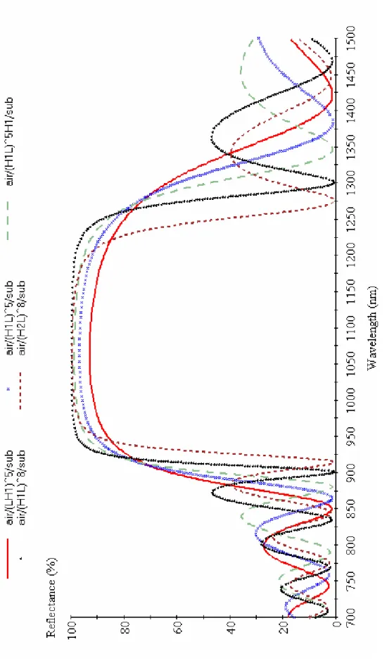
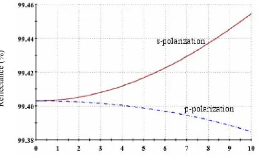
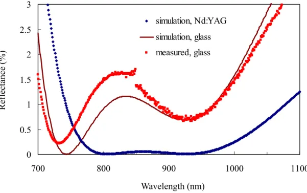
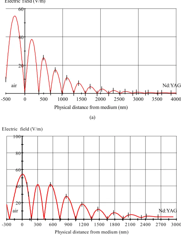
(13) Fig. 4.11. Fig. 4.12. Fig. 4.13 Fig. 4.14 Fig. 4.15 Fig. 4.16. Fig. 4.17 Fig. 4.18 Fig. 4.19 Fig. 4.20. Fig. 4.21 Fig. 4.22 Fig. 4.23 Fig. 4.24 Fig. 4.25. Fig. 4.26. The longitudinal mode measurement set up of the ring cavity. The He-Ne laser is used for alignment cause the IR light wavelength range………………………………………………… (a) The multi-longitudinal mode operation of the ring cavity without magnet field for faraday effect, (b) the single-frequency operation of the non-planar figure-eight cavity………………….. Comparison of green output power among KTPs with different lengths in the ring cavity………………………………………… The setup of green laser ring cavity with composite crystal of Nd:YVO4 with KTP……………………………………………... The green output power of ring laser with composite crystal…… The setup of bidirectional green laser ring cavity, which the gain medium is Nd:YVO4 and the doubling crystal KTP is put in the opposite position to the gain medium…………………………… The green output power with different length KTP crystal which the gain medium is Nd:YVO4…………………………………… The system set up of the polarization ellipticity measurement in the linear cavity…………………………………………….......... The output polarization of the laser at pump powers of (a) 300 mW and (b) 2000 mW…………………………………………… The diagram of the output polarization characteristics at varies pump power. The inner most linear and the outer most ring were obtained at the pump power of 0.34 W and 2 W, respectively…... Characterization of the polarization ellipse of ellipticity at different laser diode temperatures……………………………….. Characterization of the polarization rotation angle at different laser diode temperatures………………………………………..... A sketch of the relationship between optic axis and beam propagation………………………………………………………. Characterization of the polarization ellipse at laser diode working temperatures of 25oC…………………………..……….. Thermal birefringence of Nd:YAG. The left y axis is the index from simulate, the right side y axis is the index difference from experimental data………………………………………………... The 3-D schematic diagram shows the rotation of the incident plane after reflection from the cavity mirror. Points 1, 2, 3, and 4 are the laser intersections with the input and output couplers. The polarization rotates 4 times in one round trip. Beam paths 12. 94. 95 96 97 97. 98 98 100 101. 102 103 104 105 107. 108. 108 xii.
(14) Fig. 4.27 Fig. 4.28 Fig. 4.29. Fig. 4.30. Fig. 4.31. Fig. 4.32 Fig. 4.33 Fig. 4.34 Fig. 4.35 Fig. 4.36 Fig. 4.37 Fig. 4.38. and 34 are not crossed…………………………………………… The diagram of the coordinate changed as the beam reflected by the cavity mirror each time………………………………………. The beam passed the gain medium twice in a round trip at the linear cavity……………………………………………………… The comparison of simulation and experimental data in the linear cavity. At low pump power, the polarization state is linear due to the pump beam profile. At high pump power, the ellipticity of polarization ellipse becomes smaller due to thermal saturation in the gain medium………...…………………………. The comparison between simulation and experimental data. The ellipticity of polarization ellipse in the non-planar ring configuration is around 1.3………………………………………. The polarization rotation angles are significantly reduced when compared with that of the linear cavity. This is mainly attributed to the thermal saturation on the gain medium and the optic axis is stationary at high pump power........…………………………… Example of 3-D view of the laser beam in a multi-reentrant cavity…………………………………………………………...... Multi-reentrant ring laser set up. I/C: input coupler. O/C: output coupler…………………………………………………………… L/R versus d/R for various M/N ratio……………………………. Stability condition of the planar figure-8 cavity………………… (a) Stability and (b) mode size at z = 0 of empty ring cavities for N = 5……………………………………………………………... (a) Stability and (b) mode size at z = 0 of empty ring cavities for M = 1…………………………………………………………….. Non-planar figure-8 cavity with various effective thickness of gain medium. The effective gain medium thickness is defined by. 110 111. 112. 113. 114 117 118 121 123 125 127. 1 t (1 − ) , where n and t are the index and physical thickness of n R Fig. 4.39. Fig. 4.40. the gain medium………………………………………………..... 128 Cavity stability analysis using 1-mm Nd:YAG as gain medium for (a) N = 5 and (b) M = 1 cavity configurations. q is defined by (A+D)/2…………………………………………………………... 130 (a) Comparison of cavity length between the nonplanar figure-8 cavity and TEM01 mode. (b) Cavity length difference between figure-8 cavity and TEM01 for different cavity radius of xiii.
(15) Fig. 4.41. Fig. 4.42 Fig. 4.43. Fig. 4.44. Fig. 4.45 Fig. 4.46 Fig. 4.47 Fig. 4.48 Fig. 4.49 Fig. 4.50 Fig. 4.51 Fig. 4.52. Fig. 4.53 Fig. 4.54. Fig. A1. curvatures………………………………………………………... N = 2, M = 1 ring laser output beams. (a) is the output points of bidirectional beam propagation. (b) is the output point of unidirectional beam propagation. Marks 1 and 2 are for the output beams from one propagation direction, whereas marks 3 and 4 are from the other propagation direction………………….. Cavity detuning characteristics for the three ring lasers: (a) (N, M) = (7, 3); (b) (N, M) = (5, 2); and (c) (N, M) = (3, 1)………..... The passive Q-switched laser pulse observed from oscilloscope. (a) is a single period result. (b) is the envelop collected from a series of pulses…………………………………………………... A typical semi-symmetry linear cavity of passively Q-switched laser. The saturable absorber (Cr4+:YAG) is located next by the gain medium……………………………………………………... Timing jitter versus laser output power………………………...... Passively Q-switched ring laser cavity…………………………... L-I curves of different couplers transmittance…………………... Slope efficiency of different round trip transmissions…………... Peak power of the passively Q-switched ring cavity with the pulse width of 68ns and round trip loss of the cavity is 8%........... The outputs power which gain medium in a various off-axial distances…………………………………………………………. The jitter measurement set up…………………………………… The jitter measurement under unidirectional and bidirectional operations in the ring cavity. The square dots are bidirectional propagation and the jitter is around 6%, the circle dots are unidirectional propagation and the jitter is below 3.5% at various pumping powers…………………………………………………. The pulse waveform of the passively Q-switched ring cavity…... The repetition rate under unidirectional and bidirectional operations in the ring cavity. The square dots are bidirectional propagation, the circle dots are unidirectional propagation……... Beam path in (a) 3D view, (b) side view, and (c) end view…….... 132. 134 136. 140. 141 142 144 145 146 146 147 148. 149 150. 150 156. xiv.
(16) Chapter 1 Introduction Continuous single longitudinal mode lasers are useful for communication, data storage,. display,. and. measurement. applications.. Intracavity. doubling. of. continuous-wave (cw) yttrium aluminum garnet Y3Al5O12 (Nd:YAG) lasers is an efficient method of generating coherent visible light. When such lasers are end-pumped by laser diodes the overall efficiency is among the highest for lasers in this portion of the spectrum. Large amplitude fluctuations due to longitudinal mode coupling [1] have been a persistent problem, which has rendered these devices in appropriate for many applications. This amplitude noise can be eliminated by using intracavity elements such as an etalon or quarter-wave plates [2], or circumvented by placing the doubling crystal in an external resonator [3]. None of these solutions are ideal; however, since the end-pumped laser output power is highly sensitive to such losses as may be introduced by the insertion of intracavity elements, while the external cavity concept requires active stabilization to control its length so that resonance will be maintained even as the laser frequency drifts. On the other hand, a single frequency laser will naturally eliminate amplitude fluctuations in the second harmonic. To demonstrate this concept, we have developed an intracavity doubled Nd:YAG ring laser and result will be presented. This laser demonstrated exceptional performance as a single frequency unidirectional 1064 nm laser as well. The ring was operated both cw and repetitively Q-switched, providing efficient unidirectional, single transverse mode output in all case. A typical linear laser resonator consists of two mirrors facing each other, as shown in Fig. 1.1.. 1.
(17) Gain medium. (a). Gain medium. (b). Gain medium. (c). Figure 1.1. Various types of linear laser resonators. (a) Confocal, (b) hemispherical, and (c) plane parallel.. 2.
(18) These configurations create electric and magnetic field standing waves in the resonator with a period of one-half of an optical wavelength. These standing waves interact with only part of the volume of the laser material, thus creating spatial inhomogeneities in the gain medium. This effect is termed spatial hole burning [4], which causes multi-longitudinal mode oscillation as described below and illustrated in Fig. 1.2. Suppose a linear or standing-wave laser is initially oscillating in the q-th axial mode. This leads to a standing-wave pattern for the field amplitude or optical intensity along the z axis, with peaks and nulls spaced by one-half optical wavelength. The inverted population in this laser will then be saturated in a similar spatially periodic fashion. One of the effects of this saturation will be to produce a spatial inverted-population grating or gain grating, which will introduce cross-coupling between the forward and backward-traveling wave components of the q-th axial mode. Of more importance at this point, however, is the fact that, at least near the center of the cavity, the standing-wave pattern of the (q+1)-th mode which squeezes one more half optical wavelength into the cavity length will have its maximum intensity located just at the points that are left unsaturated by the q-th mode. As a result of this, the gain competition between the two adjacent axial modes is much reduced, and both axial modes may well be able to oscillate simultaneously, even with strongly homogeneous laser medium, by using in essence different groups of atoms. Oscillation with any two adjacent axial modes at equal amplitudes will then saturate the population uniformly, at least in the center of the cavity, possibly discouraging the oscillation of any further axial modes. This behavior is sometimes seen, for example, in solid-state lasers, such as the Nd:YAG laser, which often seem to prefer to oscillate at steady state in just two axial modes.. 3.
(19) (a). (b). (c) Figure 1.2. A schematic diagram illustrating the spatial hole burning effect. (a) The standing wave that oscillating in the (q+1)-th axial mode in the cavity, (b) the standing wave that oscillating in the q-th axial mode, (c) The population inversion introduced by the q-th axial mode in the gain medium [4].. Single mode laser oscillation can be obtained by insertion of a frequency selective device, which suppresses oscillation of all other modes. Various designs to generate single frequency lasers were demonstrated [5-13]. One procedure is to couple the cavity that contains the laser medium to a shorter cavity that has widely spaced resonant frequencies [14]. For Nd:YAG, the homogeneous linewidth [15] is 180 GHz, and the required length of about 0.1cm is so short that prisms [16] or beam-splitter and double-mirror combinations are very difficult to fabricate [17] as shown in Fig. 1.3.. 4.
(20) Figure 1.3. Single-frequency laser using stabilized tunable prism resonator to select wavelength and axial mode. M2: beam splitter, M1, M3, M4: laser mirrors [17].. The primary disadvantage of all the preceding mode selection devices is that the power in the suppressed mode is lost and does not contribute to the laser output. Further, each of the techniques creates some additional loss for the desired mode. As a result, the efficiency of these longitudinal mode selection devices is limited to about 50 percent in the case of Nd:YAG lasers [18]. Placing a comparatively short section of active laser medium close to one of the end mirrors is another way to reduce the effectiveness of the spatial hole-burning process [19]. Higher efficiency can be obtained by eliminating the spatial hole burning. Replace the standing wave with the traveling wave propagating in the cavity; the spatial hole burning effect will be eliminated. Ring laser cavity has been shown to be a robust method for producing single-frequency laser as operates at uni-direction propagation [20-24]. However, in 5.
(21) previous works, more than three or four mirrors for guiding of the laser light to form a closed loop formed the ring cavities. These complex configurations made the lasers bulky and expensive. In our work, a novel symmetrical two-mirror figure “8” ring cavity was demonstrated [25]. Different from the linear cavity, the propagation configuration looks like a figure “8”. With less optical components, this ring cavity is compact and free of astigmatism. The study of polarization evolution in this nonplanar, reentrant ring cavity is also made. In the numerical simulation, the factors, which affect the polarization state within the cavity, were considered. By measuring the polarization of a linear-cavity laser, we also derived the thermally induced optical axis rotation in the gain medium, and determined the equivalent temperature-dependent dielectric tensor of the gain medium at various pump powers, which enable Jones matrix analysis of the polarization in the nonplanar ring laser cavity. In addition to the figure “8” ring laser, we also demonstrate the multi-reentrant laser by the two mirror ring configuration. We not only prove that the multi-reentrant laser system is feasible experimentally, but also use fundamental laser theory to find the relation among cavity length, number of points, number of circulation, and the distance between center of gain medium and optical axis. The exact solution we obtained is experimentally verified with good agreement. A comparison between exact solution and paraxial approximation is also performed. The beam paths observing from the top, side, and end view are analyzed for various multi-reentrant laser cavities. The stability of the cavity is numerically analyzed and experimentally verified with good agreement, too. Finally, the differences in cavity configuration between TEM01 mode and the figure-8 mode are compared in this dissertation. This ring laser system can be applied in picoseconds mode-locked laser because one of the advantages of the cavity is that it can reduce the cavity length while 6.
(22) maintaining a long round-trip length as shown in Fig.1.4. This is useful for a picoseconds mode-locked laser to reduce its cavity length. Typically, the cavity length around 1 m is required as the mode locked laser operated in the 100 MHz repetition rate. By using this multi-reentrant cavity configuration, it needs only 10 cm, which will be discussed in chapter 4.. Figure 1.4. Multi-reentrant laser configuration. The cavity round length can be an order of magnitude longer than the separation of the cavity mirrors.. The other application of the multi-reentrant ring laser is the compact laser gyroscope. Gyroscope is an instrument that helps maintain orientation in space. The application fields include civil and military aviation, submarine force, and cosmonautics, the sensor of an autonomous navigation system, a compass, to keep shaft sinking or drifting direction, to hold the direction of a gun barrel on a moving platform. There are two kinds of optical gyroscopes, both based on the same principle. Laser gyroscope is a laser with ring cavity. The laser cavity is made of three or four mirrors which form of a closed loop. Fiber gyroscope is a similar device, but the beams of the laser light are traveling along a fiber optic, which is in a form of a coil [26-28]. The laser gyroscope is shown in Fig. 1.5. 7.
(23) Figure 1.5. System setup of laser gyroscope with three mirrors [26].. Two laser beams are moving in opposite directions (clockwise and counterclockwise) in the same ring path. As the gyroscope is immovable, the two light beams have the same optical path and the same frequency, as the gyroscope rotates, the rotating interferometer effectively shortens the optical path traveled by one of the beams, while lengthening the other on the same value. Light propagates in the ring laser gyroscope; the change of optical path length causes a change of the ring resonator resonant frequency. Thus, counter-propagating beams in ring resonator have different frequencies, and produce a beat frequency ∆ν , which is directly proportional to the change of path length. Optical gyroscopes are based on the principle termed Sagniac effect [29]: ∆ν = 4 AΩ λL. (1.1). where λ is the laser wavelength, A is the area enclosed by that path, L is the total path of the ring, and Ω is the rotation angular velocity of the gyroscope. From equation (1.1), by measuring the beat frequency of the two beams, we can get the angular rotation velocity of the flight vehicle. The key point of the laser 8.
(24) gyroscope technique is how to measure extremely small frequency difference. By using the multi-reentrant ring system, the optical path of laser beam propagation in the cavity is increased; this means that the effective cavity length is longer, so the measurement resolution is enhanced. Due to that, the possibility of creating an advanced rotation sensor with very high performance arises. Another possibility to use the multi-reentrant laser is absorption spectroscopy. Multi-pass cell has been widely used for the detection of weak atomic or molecular absorption lines due to its long optical path combined with compact cell volume [30-34] as shown in Fig. 1.6. The length of the commercial multi-pass cell is around 36 m to 100 m. The principle is that introduce the tunable laser to the multi-cell, after multi reflected in the multi-pass cell, the out put laser beam intensity will be detected by the balance receiver, and the absorption value of the gas can be calculated form the formula I = I 0 e. −αl. where α is the absorption coefficient, l is the total optical path. of the multi-pass cell. The major advantage of our multi-reentrant ring laser is that the measurement would be more sensitive than the multi-pass cell in Fig. 1.6. The optical coating of the two mirrors for our experiment set up are all 99.8% reflectance for the 1064nm, the loss is 0.4% in one round trip. It is known that the laser out power is very sensitive for the stability of the resonator, once the laser intensity inside the cavity has a small variation, the output power response immediately. Although the gas absorption constant is usually very small, the power vibration which causes from the oscillation photons were absorbed by the gas atom would be observed obviously.. 9.
(25) Figure 1.6. An absorption spectroscopy set-up using multipass cell [30].. Using the multi-reentrant laser cavity, the detection sensitivity can be further increased because the laser output power is much more sensitive to intracavity loss than a passive cell. Designing a laser system involves integrating a number of different technologies. One of the critical technologies is the optical coating. For solid-state laser, there are three strict criterions to the multilayer dielectric films. They are the high-reflection coatings; reflectivity should be satisfied for different wavelengths, and high damage threshold. In our investigation, we have studied solid-state laser system for years and have many related patents. To develop high efficiency solid-state laser, we have also collaborated with the Industrial Technology Research Institute, Hsin Chu, for the high quality coating technology. In this dissertation, the basic theory and some simple optical thin film design models and rules are presented.. 10.
(26) Chapter 2 Solid-state laser systems 2.1 Diode pumped solid-state lasers The first solid-state laser was flash-lamped-pumped chromium-doped sapphire crystal now referred to as the ruby laser. Following the demonstration of the ruby laser by Maiman [35-38], Nd:CaWO4 laser and Nd:YAG laser were developed [39]. Flashlamp-pumped solid state lasers were the preferred source for nonlinear optical experiments and applications for the next two decades. Early 1962, laser diode pumped solid-state lasers were proposed [40], and demonstrated [41]. The first laser diode pumped solid-state laser was operated at cryogenic temperatures, but the promise of the approach was recognized. It was not until 1978, with the demonstration of an 1 W cw laser diode bar [42], the laser diode pumped solid state laser began their rapid evolution that continues today. Diode laser pumped solid state lasers are efficient, compact, all solid state sources of coherent optical radiation. The primary commercial example of a conventional solid state laser is Nd:YAG. Nd:YAG lasers at 1.064 µm and can be frequency doubled to 532 nm, tripled to 355 nm and quadrupled to 266 nm. CW Nd:YAG lasers are available in power levels up to kilowatts watts and pulsed Nd:YAG lasers are available with pulse energies up to a few joules per pulse. Nd:YAG lasers can also be operated Q-switched or mode-locked. Q-switched Nd:YAG lasers are frequently used for laser machining processes that require rapid removal of relatively small quantities of material. Examples include trace and link blowing in the electronics industry, laser marking, and laser hole drilling. An important market niche is the use of Q-switched and frequency-doubled Nd:YAG lasers for laser marking of silicon wafers. A developing market niche is the use of Q-switched Nd:YAG lasers for removal of unwanted body hair [43]. 11.
(27) Frequency-doubled cw Nd:YAG lasers compete with argon-ion lasers for the moderate power green laser market. Thus, Nd:YAG lasers compete with argon ion lasers in such applications as printing, display technology, stereolithography, and retinal photocoagulation. A developing application for Nd:YAG lasers is laser-enhanced bonding [44], the process uses a laser to drive a polymer adhesive into the material being joined. The process provides a replacement for more traditional sewing, taping, gluing, or ultrasonic welding. Specific applications for the technology include bookbinding, laminating, textiles, injection molding, and carpeting.. 2.2 Pumping source Solid-state laser development has been paced by the improvement and discovery of pumping sources. The most efficient laser pump lamp will produce maximum emission at wavelengths which excite fluorescence in the laser material, and produce minimal emission in all spectral regions outside of the useful absorption bands. The helical lamp, used to pump the first ruby laser, was replaced by the linear flash lamp and discharge arc lamp that are now used to pump virtually every neodymium-doped yttrium-aluminum-garnet and neodymium glass laser system in the world. The latest advance in solid-state laser technology promise to be improved pumping by means of diode lasers and diode laser arrays. The recent and rapid advances in the power and efficiency of diode lasers and diode laser arrays and their application to the pumping of solid-state lasers have led to a renaissance in solid-state laser development. Advanced solid-state lasers pumped by diode lasers will make such diverse applications as coherent radar for global wind measurements, semiconductor circuit repair, and all solid state color video projection possible. Diode. laser. pumped. solid-state. laser. provides. spectral. brightness. “amplification” that is essential for many applications that require a high degree of. 12.
(28) temporal and spatial coherence. It offers a number of advantages over flash lamp pumping or the diode directly: Firstly, flash-lamp pumping efficiency is limited by the broad spectral emission of the lamp and the less efficient absorption of the lamp radiation by the solid state laser medium, but the diode laser can efficiently emit optical radiation into a narrow spectral band. Excess heat and power fluctuations of the lamp also degrade the solid state laser performance. Secondly, the diode laser is essentially a cw device with low energy storage capability, whereas the solid-state laser can store energy in the long-lived metastable ion levels. The stored energy can be extracted to provide peak power levels that are orders of magnitude greater than from the diode laser itself, for example the Q-switched laser. Thirdly, the solid state laser can collect the output from several diode lasers to provide greater average power than is available from a single diode laser. Fourthly, the diode laser pumped solid-state laser can operate at a verity of wavelengths not accessible with diode lasers. Fifthly, the linewidth of the diode laser pumped solid-state laser is fundamentally orders of magnitude less than that of the diode laser source. Sixthly, the solid-state laser source also emits optical radiation in a diffraction limited spatial beam that is easily focused into a fiber or to a small spot. Significant progress has been made in developing monolithic, linear laser-diode arrays which have become the building blocks for solid state laser pumps. Output power, slope efficiency, laser threshold wavelength control have all been dramatically improved due to a combination of new structures and advanced growth techniques. In particular, epitaxial growth based on metal organic chemical vapor deposition (MOCVD) allows close control of material composition, layer thickness and device geometry.. 13.
(29) Early semiconductor lasers were constructed from n type and p type layers of the same semiconductor material. Such lasers are called homostructure lasers. There are many problems associated with the simple p-n junction lasers which can be attributed to the fact the same material for both the p and n regions were used. Two of the critical ones are (1): The injected minority carriers are “free” to diffuse where they will, a fact that dilutes the spatial distribution of recombination and thus the gain. (2): There is very little guiding and confinement of the electromagnetic wave being amplified. There is a small bit of wave guiding caused by the slight decrease of refractive index on the n side and on the p side due to the small change in Eg with acceptor doping. However, these changes are very small, and the unpleasant fact is that the central part of the wave may be amplified with the tails, which extend into the noninverted regions, being attenuated. Both of these problems can be ameliorated by the use of heterostructures to form the active portion of the laser. Heterostructure lasers require layering these different materials. This is a very complex problem, as the materials have different physical properties. Perhaps the most important of these properties is the lattice spacing. If the materials do not have the same lattice spacing, then dislocations can appear in the semiconductor laser. In addition to the structural difficulties imposed by the dislocations, dislocations can also be highly detrimental to semiconductor laser operation as they can serve as a nonradiative sink for carriers. The majority of commercial heterostructure semiconductor lasers are fabricated from semiconductor materials in columns III and V of the periodic table. Column III is born (B), aluminum (Al), gallium (Ga), indium (In), and thallium (Tl), Column V is nitrogen (N), phosphorus (P), arsenic (As), antimony (Sb), and bismuth (Bi). Common laser materials include virtually all combinations of Al, Ga, and In, with P and As. Some work has been done with B, Al, and Ga, with N; as well as Al, Ga, and In with Sb. Very little has been done with Tl 14.
(30) and Bi. These are junctions between two dissimilar materials such as GaAs with AlxGa1-xAs, with x being the fraction of gallium being replaced by Aluminum. It is a fortuitous fact of nature that GaAs and AlAs semiconductors have almost identical lattice constants as shown in Table 2.1 and thus can be mixed and can be grown on top of each other with little strain involved and a very small density of traps at the interface. This metallurgical fact is critical to the success of making the junction.. Table 2.1: Properties of common semiconducting materials. me∗ m0. Lattice constant. --. (Å). 1200. 0.2. 3.5668. 1600. 100. 0.82. 5.4512. 10.9. 180. --. --. 5.6605. 1.43. 13.2. 8500. 400. 0.067. 5.6533. InP(d). 1.35. 12.4. 4600. 150. 0.077. 5.8686. Si(i). 1.12. 11.9. 1500. 450. 1.1. 5.4309. GaSb(d). 0.72. 15.7. 5000. 850. 0.042. 6.0957. InAs(d). 0.36. 14.6. 33,000. 460. 0.023. 6.0584. InSb(d). 0.17. 17.7. 80,000. 1250. 0.0145. 6.4794. µe. µh. Band gap. εr. Material. (eV). --. C(i). 5.47. 5.7. 1800. GaP(i). 2.26. 11.1. AlAs(i). 2.16. GaAs(d). (cm2/V-sec). Note: i stands for indirect bandgap, d stands for direct bandgap.. A very useful diagram for visualizing lattice match in heterostructure lasers is the energy versus lattice constant diagram. An example of such a diagram for III-V materials is given in Fig. 2.1. Notice that only the AlAs-GaAs system is lattice-matched across the entire compositional range. This is one major reason for the 15.
(31) widespread use of AlGaAs/GaAs heterostructures on GaAs substrate for semiconductor laser diodes [45].. Figure 2.1. The energy gap versus lattice constant diagram for compound semiconductors [45].. In a ternary alloy, the lattice constant is linearly dependent on the composition. The linear relationship of the lattice constant generally holds for quaternary alloys too. However, other parameters, of a mixed alloy do not, in general, obey this linear relationship. The bandgap, for example, is usually given by an empirical relationship, E g ( x ) = E go + bx + cx 2 , where E g is the bandgap of the lower bandgap binary, b is a. fitting parameter, and c is called the bowing parameter, which may be calculated theoretically or determined experimentally. It is not only the variation of bandgap with composition, but also the energy variation of the higher-lying bandstructure with. 16.
(32) composition, that is extremely important for the understanding of material properties. As the percentage of aluminum is increased, the band gap increases and the index of refraction goes down, and this asynchronous behavior is true for quaternary alloy combinations also. Figure 2.2 illustrates the dependence of the band gap and the index of refraction on the mole fraction of Al substituted for gallium. These graphs are plots of the analytic expressions for Eg and the index given by reference [46-49].. [. ]. E g (direct ) = 1.424 + 1.247 x + 1.147(x − 0.45) , 2. E g (indirect ) = 1.900 + 0.125 x + 0.143 x 2 ,. x ≥ 0.45 x ≤ 0.45. n( x ) = 3.590 − 0.710 x + 0.091x 2. 1000. 3.2 AlxGa1-xAs T = 297 K. 808 nm. 900. 2.8. 700. 2.4. 600 500. 2.0. 400 300 200. wavelength (d). wavelength (i). bandgap (d). bandgap (i). 1.6. Band gap Eg (eV). Wavelength (nm). 800. 1.2. 100 0.8. 0 0 GaAs. 0.2. 0.4. 0.6 x. 0.8. 1 AlAs. (a). 17.
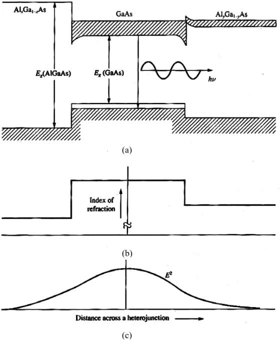
(33) 3.6. 1000 900 800. 3.4. 700 600. 3.3. 500 3.2. 400 300. 3.1. Wavelength (nm). Refractive index n. 3.5. 200. 3. 100. 2.9. 0 0. 0.1. 0.2. 0.3. GaAs. 0.4. 0.5. 0.6 x. 0.7. 0.8. 0.9. 1 AlAs. (b) Figure 2.2. (a) Compositional dependence of direct and indirect conduction band minima in the AlxGa1-xAs mixed crystals, (b) dependence of the index of refraction on the fraction, x, of aluminum in the composition.. Figure 2.3 illustrates a laser using a double heterostructure geometry and is shown biased in the forward direction. Shown also is the variation of the refraction index and the light intensity in a plane perpendicular to the junction. Note that the electrons injected from the n-type AlxGa1-xAs material are confined to and recombine in lower band-gap p-type GaAs.. 18.
(34) (a). (b). (c). Figure 2.3. (a) The band diagram for a forward-biased heterostructure, (b) the refractive index, and (c) a sketch of the light intensity in the vicinity of the active region.. 19.
(35) In designing a diode-array-pumped laser system, we must select the array configuration for the proposed application. Several common configurations are available. These include small linear arrays with a length of 100 or 200 µm, 1-cm long array bars, and stacked diode bars. For high power lasers, the 1-cm linear bars must be combined into modules at some level to reduce complexity of the electronic drivers, heat removal and mechanical structure. Stacking of diode arrays is done manually or in a semi-automated mode at the present time. This process allows large-area arrays with dimensions up to about 1 cm2 to be fabricated. However, the process is labor intensive. The cost of the arrays also increases faster than linearly as the size of the array increases. This is because the selection of wavelength and current threshold of linear bars that constitute the arrays becomes more critical as the size of the array increases. All of the bars in the array must be matched for optimum performance. A trade off exists between increased design complexity using arrays which consist of only a few bars and reduced efficiency and increased cost with large area arrays comprised of a large number of bars. As a result of this trade off, a common module for high power lasers is an array consisting of 5 one-cm bars. Such an array has an aperture of about 10×1 mm2. Semiconductor laser technology has produced an amazing variety of new device structures in the past decade. Overviews of this technology made possible by sophisticated growth techniques such as metallorganic chemical vapor deposition and molecular beam epitaxy can be found in [50-51]. The key design features of diode lasers by describing the single quantum well separate confinement heterostructure (SQW-SCH) will be illustrated, because it is the most widely employed design for solid state lasers pumps. The active layer shown in Fig 2.4 is sandwiched between two pairs of layers having a different concentration of Al. The main purpose of the innermost pair of 20.
(36) layers is to confine the carriers to the active region, whereas the purpose of the outer layers is to confine the optical beam. In a diode laser, recombination of current carriers takes place in a thin active layer which separates p- and n-doped regions.. Figure 2.4. Gain-guided, single quantum well separate confinement heterostructure stripe laser. Thickness of layers is greatly exaggerated. Optical mode cross-section is actually 5µm wide and 0.5 µm high.. Progress in high power laser diodes for solid state laser pumping has emphasized the development of quantum well structures in which laser emission is produced in very thin epitaxial layers (quantum wells) less than 0.02 µm thick. A quantum well is a thin layer of semiconductor located between two layers with larger bandgap. Electrons in the quantum well layer lack the energy to escape, and cannot tunnel through the thicker surrounding layers. The quantum well layer in Fig 2.4 has a composition of Ga and Al indicated by x which defines the emission wavelength. A higher Al concentration increases the bandgap and shifts the output towards shorter wavelength. The quantum well structure is sandwiched between two 21.
(37) thick layers of composition which contains a higher concentration (y>x). The higher Al concentration increases the bandgap, thereby defining the quantum well, and the large thickness of the layer prevents tunneling of the carriers out of the quantum well. Single quantum well devices exhibit slightly lower lasing thresholds and slightly higher differential quantum efficiencies, making them preferable for high power lasers. The thin active region incorporating a quantum well active layer structure provides low threshold and high electrical-to-optical efficiency. However, such a very small emitting surface poses one problem since the power from a diode laser is limited by the peak flux at the output facet. One can increase the output from these devices by spreading the beam over an area which is larger than the active layer or gain region. The standard approach is to deposit layers next to the active layer, each of which has a slightly lower refractive index than the active layer, thus making a wave guide of the active layer. In the separate carrier and optical confinement heterostructure design shown in Fig. 2.4, the refractive index boundary is abrupt, at the layer boundary. Alternatively, the refractive indices of the surrounding layers may be graded, forming a graded-index and separate carrier and optical confinement heterstructure. In the SQW-SCH structure, the overlap between the optical mode and the gain region is only about 4%, which results in a large effective aperture of the laser on the order of 0.3 to 0.5 µm. This substantially reduces the energy density at the output facet and enhances reliability by minimizing characteristic facet damage. In the GaAlAs diode laser, the wavelength changes with temperature according to 0.3 nm/oC. More powerful arrays with outputs up to 3W are on the market, however the greater aperture width of these devices makes coupling of the pump beam into the small mode volume of the solid state laser fairly inefficient. 22.
(38) The key concept in diode-pumped solid-state lasers is to make the output mode of the diode laser precisely match the operating mode (usually TEM00) of the laser. The simplest possible configuration is to end pump a solid-state laser rod with a single laser diode as shown in Fig. 2.5.. Figure 2.5. In the end pumped geometry, the light is directed down the length of the rod.. Commercially available diode arrays suitable for endpumping contain a small number of stripe lasers on a single chip, as shown in Fig. 2.6.. Figure 2.6. Multistripe semiconductor laser array geometry.. A typical example is a 20 stripe gain guided, SQW-SCH laser array made by Spectra Diode Laboratories (Model SDL-2460) as shown in Fig. 2.7. The diode array contains twenty 5-µm-wide stripe lasers on 10 µm centers which produce a total output of 1W in the cw mode. The output is emitted from an area of 200 * 1.0 µm with a beam divergence of 40o by 10o. 23.
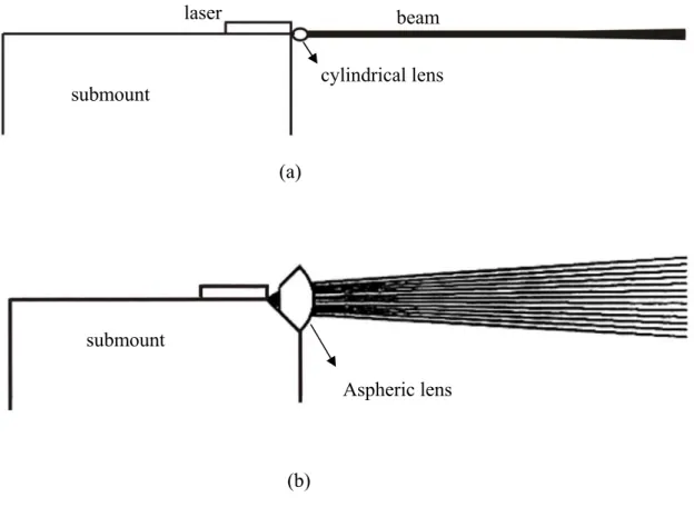
(39) (a). (b). Figure 2.7. The (a) outlook and (b) cross-section view of 1-W laser diode (SDL-2460).. Because laser diodes tend to lase with an output mode promising a highly elliptical beam due to the difference between the horizontal and vertical dimensions of the lasing region of the diode, there are two major problems associated with this output mode. The first problem is the large astigmatism. The second is the huge divergent angle. Typically, a large-aperture lens is placed close to the laser in order to capture as much energy as possible. Then, some type of astigmatism compensation is used. Finally, the beam is refocused into the optimal configuration for mode matching into the rod. Traditional techniques for compensating for the astigmatism include coupling the beam into a fiber or using a GRIN lens. However, both of these techniques intrinsically strip off part of the beam as the beam mode matches into the optical element. Thus, fiber or GRIN lens coupling techniques are inefficient. More efficient techniques include using aspherical lenses (expensive) or anamorphic prisms [52] (cheaper but more complex to assemble). The anamorphic prism technique is 24.
(40) probably the most commonly used in commercial diode pumped lasers because it is highly efficient and relatively low cost as shown in Fig. 2.8.. Figure 2.8. Anamorphic prisms are often used for compensating for the astigmatism of a laser diode.. Some microlens options are also offered. One is a simple lens (actually a round optical fiber). The other is an aspheric design that provides diffraction limited performance. These lenses are cylindrical lenses that modify the divergence of the fast (high divergence) axis of the laser diode: the lenses have no effect on the slow (low divergence axis). The lenses may be focused to attain best collimation, or may be focused to equalize the divergence of the slow and fast axes as shown in Fig. 2.9.. 25.
(41) laser. beam cylindrical lens. submount. (a). submount Aspheric lens. (b) Figure 2.9. (a) A standard offering of the round simple cylindrical microlens of 125 µm diameters, (b) the aspheric microlens which designed to provide a diffraction limited 8X magnification of laser diode fast axis (Polaroid laser diode manufacturing & development product literature).. End-pumping of laser rods with diode laser arrays (rather than single diodes) is also done. However, some care must be taken in these designs, as it is much more difficult to mode match laser arrays into the relatively small end face of the rod. Therefore, the additional power advantage achieved with the laser diode array may be offset by the mode matching disadvantages of the geometry. End-pumping of laser rods with fiber-coupled laser arrays is an effective solution to the design problem of mode matching laser arrays into the small end face of the rod. However, creating the. 26.
(42) fiber bundle requires coupling a fiber into the end of each individual laser diode in the array. This adds significant cost and complexity to the pump system.. 2.3 Gain medium A common solid-state laser material consists of an optically transparent host such as glass (mostly SiO2), YAG, sapphire (Al2O3), etc., doped with a small amount of a rare earth ions (the rare earths are those elements with atomic numbers from 57 to 71 with two of the most important being Nd 60 and Er 68 ). The active atom is the rare earth and usually acts as if it was triply ionized since the outermost three electrons are involved in the bonding (the solid-state material is charged neutrally). Some of the unique laser properties arise because of a subtle point appearing in nature. In the rare earths, the active electron participating in the optical transition is one of the 4f electrons that is shielded by electrons in the larger n = 5 and 6 shells (or orbits). One of the consequences is that the energy levels of rare earths are only weakly dependent on the host lattice. Thus, while there are small changes in the wavelengths of the RE laser depending on the host lattice, those changes appear in the third or fourth significant figure. Per usual, we depend upon experiment to identify the character of the quantum states, the energy levels, any nonradiative quenching rates, branching ratios, the Einstein coefficients, and the transition probabilities. The characteristics of the quantum states are usually specified by the spectroscopic name to the following scheme. superscript = number. [Letter]subscript = number. The letter symbol indicates the orbital angular momentum quantum number according to the following prescription: Letter. S. P. D. F. G. H. I. etc.. L=. 0. 1. 2. 3. 4. 5. 6. etc.. 27.
(43) The numerical value for the superscript = 2S+1, where S is the spin angular momentum. The numerical value for the subscript = J, where J is total angular momentum quantum number. A level such as 4I9/2 (the ground state of the neodymium) is referred to as “quartet-I-nine-halves” and from its “name”, we immediately know that the degeneracy of that level is g = 2J+1 = 10. In other words, there are 10 different orthogonal wavefunctions describing this state. A common solid state laser material is made by doping a rare earth, neodymium, into a variety of host materials, with the most common ones being amorphous glass and crystalline YAG. In each case, the active atoms participate as if they were triply ionized, Nd3+, with energy levels and broadening of the states dependent on the host lattice. The dopant (1% to 3%) goes into the amorphous glass at random sites, and thus each Nd3+ ion “sees” a slightly different environment. On the other hand, the Nd3+ substitutes for Y3+ in the cubic crystal of YAG, and thus each of these dopant atoms sees more or less identical environments. It should come as no surprise then that the glass laser transition is inhomogeneously broadened with a comparatively wide line, whereas the YAG transition line widths are much smaller. While the YAG and the glass laser resemble each other, both lasing at λ0 ~1.06 µm, they are sufficiently different to warrant separate discussions. Pure YAG is an optically isotropic crystal with a cubic structure characteristic of garnets. Because of the difference in size of the Nd3+ that is substituted for Y3+ (about 3%), one is limited in the amount of neodymium that can be included to about 1%; otherwise, the crystal becomes severely strained. Because the active atoms are in a well defined environment, the energy levels are well defined and narrow and are shown in Fig. 2.10 part (a) with a greater detail in Fig. 2.10 part (b) where the. 28.
(44) dominant laser transition at λ0 =1.064 µm is shown as the transition between the upper state of the 4F3/2 at 11507 cm-1 and the lower state 4I11/2 at 2110 cm-1. In Fig. 2.10 part (c) the energy levels are shown presuming that the host lattice was cooled to liquid nitrogen temperatures [53]. Specific data on the various transitions, arranged in order of wavelength, are given in Tables 2.2 and 2.3.. 29.
(45) (a). (b). Figure 2.10. Energy level for neodymium in YAG. (a) Structure of Nd:YAG showing the pumping routes with the percentages referring to a pump with a broad spectral output, (b) details of the manifold at 300K showing the dominant transition, the semiconductor laser pumping route are also shown, the number in parentheses is energy levels at 77 K [53]. 30.
數據
![Figure 2.1. The energy gap versus lattice constant diagram for compound semiconductors [45]](https://thumb-ap.123doks.com/thumbv2/9libinfo/8768090.210685/31.892.165.727.256.639/figure-energy-versus-lattice-constant-diagram-compound-semiconductors.webp)
+7
![Table 3.1: The comparison of several kinds of deposition methods [91] E-gun deposition Ion assisted deposition Plasma sputtering Ion beam sputter deposition Kinetic energy (eV) ~0.1 0.1~1 1~10 >10 Working pressure (Torr) 10 -4 10 -4 10](https://thumb-ap.123doks.com/thumbv2/9libinfo/8768090.210685/82.892.141.752.171.592/comparison-deposition-deposition-deposition-sputtering-deposition-working-pressure.webp)
相關文件
The coordinate ring of an affine variety is a domain and a finitely generated k-algebra.. Conversely, a domain which is a finitely generated k-algebra is a coordinate ring of an
The coordinate ring of an affine variety is a domain and a finitely generated k-algebra.. Conversely, a domain which is a finitely generated k-algebra is a coordinate ring of an
You are given the wavelength and total energy of a light pulse and asked to find the number of photons it
substance) is matter that has distinct properties and a composition that does not vary from sample
好了既然 Z[x] 中的 ideal 不一定是 principle ideal 那麼我們就不能學 Proposition 7.2.11 的方法得到 Z[x] 中的 irreducible element 就是 prime element 了..
Wang, Solving pseudomonotone variational inequalities and pseudocon- vex optimization problems using the projection neural network, IEEE Transactions on Neural Networks 17
volume suppressed mass: (TeV) 2 /M P ∼ 10 −4 eV → mm range can be experimentally tested for any number of extra dimensions - Light U(1) gauge bosons: no derivative couplings. =>
Courtesy: Ned Wright’s Cosmology Page Burles, Nolette & Turner, 1999?. Total Mass Density
