Application of Two-Dimensional Nonuniform Fast
Fourier Transform (2-D NUFFT) Technique to
Analysis of Shielded Microstrip Circuits
Ke-Ying Su and Jen-Tsai Kuo, Senior Member, IEEE
Abstract—A two-dimensional nonuniform fast Fourier
trans-form (2-D NUFFT) technique is developed for analysis of microstrip circuits in a rectangular enclosure. The 2-D Fourier transform of a nongrid point is approximated by Fourier bases in a square neighborhood with( + 1) by ( + 1) grid points. The square neighborhood can be reduced to an octagonal region with 2 2 + 3 + 1 grid points without sacrificing accuracy if is sufficiently large. This technique allows an arbitrary dis-cretization scheme on conductors and shows a great flexibility for the analysis. Asymmetric rooftop functions are inevitably used to expand surface current densities on conductors. Based on the spectral-domain approach, all elements of the final method-of-mo-ments matrix are double summations of products of a weighted Green’s function and trigonometric functions. By using the pro-posed technique, the double summations at all sampled points can be obtained via the 2-D NUFFT. The scattering parameters of a compact miniaturized hairpin resonator, an interdigital capacitor, and a wide-band filter are calculated. The calculated results show good agreement with measurements.
Index Terms—Method of moments (MoM), nonuniform fast
Fourier transform, spectral-domain approach (SDA).
I. INTRODUCTION
C
HARACTERIZATION of microstrip discontinuities is an important task in computer-aided design (CAD) of mi-crostrip circuits. Many methods for modeling the discontinuities have been developed, such as the finite-difference time-domain (FDTD) method [1], [2], spectral-domain approach (SDA) [3], [4], finite-element method (FEM) [5], method of lines [6], [7], integral equation (IE) [8], [9], and mode-matching technique [10].The method of moments (MoM) is a core engine for anal-ysis of microstrip circuits [3], [4], [8], [9], [11]–[15]. Most of CPU time is consumed in evaluation of the MoM matrix ele-ments since the Green’s functions converge slowly and a large number of basis functions are required for expanding surface current densities on conductors. In [11], the MoM matrix ele-ments are linear combination of eleele-ments of precomputed index tables that are computed from the two-dimensional discrete fast
Manuscript received April 14, 2004; revised June 20, 2004. This work was supported in part by the National Science Council, Taiwan, R.O.C., under Grant NSC 91-2213-E-009-126 and Grant NSC 93-2752-E-009-002-PAE.
K.-Y. Su was with the Department of Communication Engineering, National Chiao Tung University, Hsinchu 300, Taiwan, R.O.C. He is now with the De-sign Service Division, Taiwan Semiconductor Manufacturing Company Ltd., Hsinchu 300, Taiwan, R.O.C.
J.-T. Kuo is with the Department of Communication Engineering, National Chiao Tung University, Hsinchu 300, Taiwan, R.O.C. (e-mail: [email protected]).
Digital Object Identifier 10.1109/TMTT.2004.842475
Fourier transform (2-D FFT). In this method, however, the mesh scheme is restricted to be uniform. Obviously, uniform grids are very inefficient for analysis of a general microstrip circuit because electric currents have rapid variations along microstrip edges, thus, fine local discretization becomes a must for accurate analysis of the whole circuit. In [12], for reducing the number of unknowns, the currents are expanded by a linear combination of the current distributions at the first few resonant modes of the circuit. However, very fine discretization and a 2-D FFT of large size are still required to find solutions at the resonant modes.
In [13], microstrip discontinuities on a lossy multilayered sub-strate are analyzed based on the electric-field integral-equation (EFIE) formulation. The conductors are uniformly discretized. At least two important points in regard to convergence of results are reported. One is that required number of summation terms in calculating the MoM matrix elements must be at least 1.25 times the total number of segments, and the other is that the mesh sizes must be no larger than and , respectively, in trans-verse and longitudinal directions for accurate calculations.
Nonuniform meshes are used in the mixed-potential inte-gral equation (MPIE) [14] to overcome the large-size matrix problem caused by uniform discretization. The acceleration procedure is at a Green’s function level, and efficient MoM techniques with rectangular, but nonuniform and nonfixed, meshes can be constructed.
In this paper, a two-dimensional nonuniform fast Fourier transform (2-D NUFFT) [15] incorporated with the SDA is developed for analysis of microstrip circuits. The mesh scheme for the microstrip circuit can be very flexible, although each subdivision must be rectangular. This idea is extended from the NUFFT algorithms in [16] and [17]. The concept for evaluating the FFT of one-dimensional (1-D) nonuniform data is to approxi-mate the exponential function at each nonuniform sampled point by interpolating oversampled uniform Fourier bases with coefficients. The order of arithmetic operations is found to be
with being the oversampling rate and being the FFT size. The accuracy of the approximation is increased as and are increased. The increase of , however, will increase the size of the FFT, thus, is usually chosen to be 2. When , accuracy of the data obtained by a least square error sense [17] is more than one order higher than that calculated by the method in [16]. In [18], the authors apply the NUFFT technique to analysis of multiple coupled microstrip lines.
The 2-D NUFFT for two-dimensional nonuniform data in the – -plane can be established by employing two 1-D NUFFTs in the - and -directions. The interpolated coefficients of oversampled 2-D FFT bases are simply the products of two
Fig. 1. 2-D NUFFT algorithm: exponential function at a nonuniform sample point(x ; y ) is approximated by Fourier bases at (q + 1) 2 (q + 1) uniform oversampled grids (X ; Y ) in a square neighborhood or by those in an octagonal neighborhood.
sets of coefficients. However, it is found that the 1-D co-efficients decay exponentially, as the bases are far away from the sample point [16]. It means that these coefficients have only negligible contribution and the number of the required coeffi-cients can be significantly reduced to save a lot of operations without deteriorating accuracy.
In this paper, Section II formulates the 2-D NUFFT algo-rithm and Section III incorporates the 2-D NUFFT in the SDA for microstrip circuit analysis. Section IV addresses the accu-racy of the 2-D NUFFT and presents calculation examples in-cluding a microstrip hairpin resonator, an interdigital capacitor, and a wide-band filter. The results are also validated by mea-surements.
II. 2-D NUFFT ALGORITHM
In Fig. 1, the cross is a nonuniform sample point and , and the circles and large black dots are uniformly oversampled grids , which are called the square neighborhood of herein. We are going to evaluate the following 2-D Fourier transform:
(1)
where and are finite complex sequences and and are even integers. The first step of the 2-D NUFFT algorithm is to determine the interpolation coefficients for ap-proximating the following exponential function with accuracy factors ’s:
(2)
where and denote the
inte-gers nearest to and , respectively. The accu-racy factors ’s are chosen to minimize error of (2) in a least square sense [17].
Substituting (2) into (1) yields
(3) where
(4) Calculation of (4) can be performed by a regular 2-D FFT of size . In (3), the 2-D interpolated coefficients can be obtained by two sets of 1-D NUFFT coefficients, i.e., the square neighborhood in Fig. 1. It is found that some of have negligible magnitudes, as they are away from , and these points have to be removed from the approximation for computation efficiency. If the coefficients associated with these insignificant grid points are directly removed from the square neighborhood, however, the accuracy of (3) can be significantly reduced. The accuracy can be recovered if the coefficients of selected grid points are derived in a least square error sense, as the 1-D case in [17]. Let the coefficients be expressed as
(5) One efficient way to obtain closed forms of the reduced square regular Fourier matrix and reduced column vector is to extract them from a full regular Fourier matrix and a full column vector with grid points. Here, and can be obtained by extending the 1-D method in [17]. The pro-cedure for determining and is as follows.
1) Define a vector product as
(6) and let
(7) and
be rows of the regular Fourier matrix for 1-D problem,
where . The th row
of then equals . It is noted that depends on and , but is independent of and .
2) Choose ; then the
th element of can be derived as
(9)
where .
3) Extract and from and , respectively. The indices of square grid points are
, and the indices of octagonal grid points, the large black dots in Fig. 1, called octagonal or nonsquare neighborhood herein, are
. Let this index sequence be , then the th element of is the th element of , and the
th element of is the th element of .
4) Evaluate in (4) by a regular 2-D FFT of size . 5) Calculate in (3) using and the
interpolated coefficients .
We test 2 pairs of generated by the random number generator of MATLAB software, and compare the 2-D NUFFT results with that obtained by direct summation (1). It is found that, when , the coefficients associated with grid points in the reduced neighborhood are sufficient to provide results with accuracy of the same order as that in the square neighborhood. Additional results will be presented and discussed in Section IV.
III. INCORPORATING THE2-D NUFFT INTO THESDA For a microstrip circuit enclosed in a rectangular shielded box of dimensions , one of the spatial-domain Green’s functions can be written as [11]
(10)
where , and is the Green’s
function in the spectral domain [19]. Other Green’s functions of the structure can be expressed in a similar manner.
In the solution procedure, asymmetric rooftop functions are used to expand current densities on conductors, and the half-rooftop functions in [20] are used for modeling those at source and load terminals. Let the current densities be expressed as
(11)
where and are unknown constants to be determined. The Fourier transform of the basis functions can be easily derived. For example, let the th basis function for the current in the
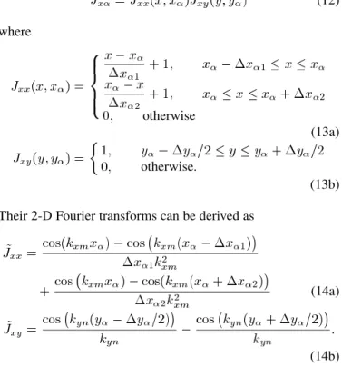
-direction be (12) where otherwise (13a) otherwise. (13b) Their 2-D Fourier transforms can be derived as
(14a)
(14b) It is important to note that the transforms (14) are trigonometric functions weighted by powers of or . It can be validated that the transforms of basis functions for currents in the -direc-tion can be expressed in a similar way.
The Galerkin’s procedure is used to set up the final MoM matrix, of which the th element can be expressed as
(15) After some algebraic manipulations with simple trigonometric identities, evaluation of can be reduced to
(16)
where or and and or .
Fig. 2 summarizes the procedure for establishing the final MoM matrix. First, partition the circuit and find the required 2-D NUFFT interpolation coefficients for four sets of sampling points . Second, evaluate the double summa-tions of products in (16) by the 2-D NUFFT. If the impressed and load currents are in the same directions, only five calls of 2-D NUFFTs will be needed. Finally, recombine the five sum-mations to set up the final MoM matrix.
When the currents on input and output feed lines are obtained, the complex amplitudes of the incident and reflected current
Fig. 2. Solution procedure for evaluating the MoM matrix.
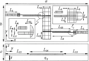
Fig. 3. Hairpin resonator in shielded box and its mesh scheme in analysis. Structure parameters are" = 10:2; L = 0:7; L = 1:01; L = 2:74; L = 8; L = 6; w = 1; w = 1:19; g = 0:2; and g = 0:8. All dimensions are in millimeters.
waves can be extracted by using the generalized pencil-of-func-tion (GPOF) method [21], and the scattering parameters can be obtained via standard circuit theory.
IV. RESULTS
Three examples are used to demonstrate the proposed tech-nique for analyses of microstrip circuits. They include a com-pact miniaturized hairpin resonator [22], microstrip interdig-ital capacitor, and wide-band bandpass filter [23]. Consider a hairpin resonator with a mesh scheme shown in Fig. 3. The thickness of dielectric substrate is mm, and the dimen-sions of shielding box are 23.6 18.15 16 mm . To reflect rapid current density variations near edges of conductors, the sampling points are chosen according to , where , and can be the length or width of the conductor. A uniform sampling, however, is used herein on feeding lines in the -direction, as indicated in the plot, which is required by the GPOF method.
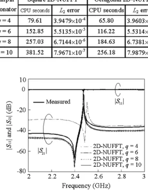
Table I lists the CPU seconds and errors in analysis of the hairpin resonator obtained by the 2-D NUFFTs with octagonal and square neighborhoods for and . The CPU time is measured with a MATLABprogram of version 5.3 on a personal computer with a Pentium IV processor of 1.6 GHz.
TABLE I
COMPARISON OFCPU TIME ANDL ERROR OFONECALL OF THE2-D NUFFTINANALYSIS OF AHAIRPINRESONATOR
Fig. 4. Measured and calculatedS-parameters of the hairpin resonator.
The calculation of the error is based on the results obtained by direct computation of (1).
Both the square and octagonal schemes have identical reg-ular Fourier matrices and column vectors for determining the interpolated coefficients, which have closed-form expressions and are independent of frequency. It means that the interpola-tion coefficients can be stored in computer memory once the mesh scheme is defined. Thus, the CPU time for steps 1–3 is not included in Table I. In step 4, the CPU time for one regular
2-D FFT with size 2 2 , i.e., and ,
takes 3.02 s. The CPU time in Table I accounts for the calcula-tion of in (3) using and the interpolated coefficients.
Comparing the CPU seconds listed in Table I, one can see that the octagonal 2-D NUFFT uses only 76%, 72%, and 67% of that for the square neighborhood for and , respectively. In comparison with the errors, the octagonal and square 2-D NUFFTs have very close values for all listed values. Note that the errors decrease about one order in magnitude as is increased from 4, 6, 8, to 10.
Fig. 4 compares the simulation results with measurement data of the hairpin resonator. The shielding box is included in the ex-periment. The peak and deep frequencies of the curve for
have the least accuracy, while those for and have close values and a good agreement with the measured data. Away from these two frequencies, the three curves have 4–5 dB and 3–4 dB away from the measurement at 2.1 and 2.9 GHz, re-spectively. Since the results for and have very good consistency, is used for simulation herein.
Fig. 5. Normalized currents on the hairpin resonator at resonant frequencyf = 2:473 GHz. (a) jJ (x; y)j. (b) jJ (x; y)j.
Fig. 6. Microstrip interdigital capacitor and its discretization in analysis. Structure parameters are" = 10:2; L = 8; L = 1:6; L = 0:8; L = 1:2; L = 7:9; d = 0:4; e = 0:4; g = 0:2; and s = 0:2. All dimensions are in millimeters.
Fig. 5 plots magnitudes of the current densities on the hairpin at resonance. Both and are normalized with respect to the maximum in the circuit. The currents show relatively large magnitudes at edges and corners of the resonator. It re-flects flexibility and necessity of the nonuniform mesh scheme in efficient analysis of a planar microstrip circuit.
Fig. 6 plots the discretization of the interdigital capacitor. The dimensions of the shielded box are 18.6 18.6 16 mm . This circuit is chosen for demonstration due to its electrically small alternative fingers and gaps, and it is tough for simulation. In our nonuniform discretization, 327 cells are generated.
Fig. 7 shows the -parameters of the interdigital capacitor ob-tained by the octagonal 2-D NUFFT with . The simulation results obtained by the proposed method have a good agreement with the measurements including the enclosure. The CPU time for a frequency point is 123.69 s.
The structure is also simulated with the commercial soft-ware SONNET and the results are incorporated into Fig. 7. In SONNET simulation, two uniform discretizations are used. In the first, mm and mm, and it results in 1274 subdivisions. One frequency point takes 5 s in total. The second discretization uses mm, and it results in 3865 subdivisions. The Fourier transform, matrix filling, and matrix solver take 12, 55, and 63 s, respectively. One frequency point takes 130 s. Both cases have very close results. It can be
Fig. 7. Measured and calculatedS-parameters of the interdigital capacitor.
seen from Fig. 7 that the three sets of plots are in a reasonable agreement.
Comparing with the CPU seconds used in SONNET, we sug-gest that source codes for the FFT and matrix solver be imple-mented in a low-level computer language for saving the com-putation time. It is noted that our codes are developed under the MATLABenvironment.
The third example is a microstrip wide-band filter in a shielded box of sizes 30.352 30.352 16 mm . The dimen-sions of circuit layout are adopted from [23]. Fig. 8 shows the circuit division in our analysis. The reason why the circuit is chosen for demonstration is that the structure consists of two pairs of coupled microstrips with a very narrow linewidth and gap size of 0.125 mm and a section of wide microstrip of 7.74-mm width. Such a structure consists of strong dis-continuities at impedance junctions, which definitely need a fine discretization for simulation. Again, if a uniform mesh is used, either the narrow coupled lines will have insufficient cells for accurate analysis or the final MoM matrix may have an unacceptably large size for fine discretizations. Here, only 353 nonuniform cells are used, and 344 and 306 basis functions are used for and , respectively.
Fig. 9 plots the simulation and measured -parameters for the filter. The distance between the circuit and sidewalls is over 1.45 times the width of the low-impedance microstrip, and the top cover height is over 24 times the substrate thickness. These two sizes are chosen to approximate the circuit in an open space, as in [23]. The calculated results show a reasonable agreement
Fig. 8. Shielded microstrip wide-band filter and its associated mesh.L = 8; L = 0:56; L = 0:576; L = 0:69; L = 0:3605;L = 0:125; L = 0:125; L = 0:125; L = 5:19; L = 4:88; L = 0:38; L = 2:06; L = 1:9; L = 7:75; L = 11:3; t = 0:635; c = 16; " = 10:8. All dimensions are in millimeters.
Fig. 9. Measured and calculatedS-parameters of the wide-band filter.
with the measurements given in [23]. The CPU time for gener-ating a frequency point is 122.31 s.
V. CONCLUSION
A 2-D NUFFT technique incorporated with the SDA has been proposed for efficient analysis of microstrip circuits in a rect-angular enclosure. In this method, the mesh scheme has good flexibility since conductors can be discretized into fine cells near the edges and relatively large cells in regions with smooth cur-rent densities. The 2-D NUFFT algorithm can be implemented with grid points in a square or octagonal, i.e., reduced neighbor-hood. The convergence of the 2-D NUFFT algorithm has been discussed. As compared with a square neighborhood, the approx-imation with octagonal grid points leads to a smaller MoM matrix and preserves accuracy of results. In analysis of three microstrip circuits, each entry in the final MoM impedance matrix has five types of double summations, and all entries of each type can be obtained via one call of the 2-D NUFFT. The scattering param-eters of the hairpin resonator, an interdigital capacitor, and a wide-band filter are calculated and validated by measurements. The 2-D NUFFT algorithm has been proven as a useful ad-vance in the efficiency of MoM calculation. It may have wide-spread applications in science and engineering.
REFERENCES
[1] X. Zhang and K. Mei, “Time-domain finite difference approach to a cal-culation of the frequency-dependent characteristics of microstrip dis-continuities,” IEEE Trans. Microw. Theory Tech., vol. 36, no. 12, pp. 1775–1787, Dec. 1988.
[2] D. Bica and B. Beker, “Analysis of microstrip discontinuities using the spatial network method with absorbing boundary conditions,” IEEE
Trans. Microw. Theory Tech., vol. 44, no. 7, pp. 1157–1161, Jul. 1996.
[3] R. H. Jansen, “The spectral-domain approach for microwave integrated circuits,” IEEE Trans. Microw. Theory Tech., vol. MTT-33, no. 10, pp. 1043–1056, Oct. 1985.
[4] , “A 3D field theoretical simulation tool for the CAD of millimeter wave MMICs,” Alta Freq., vol. LVII, pp. 203–216, 1988.
[5] R. W. Jackson, “Full wave, finite element analysis of irregular microstrip discontinuities,” IEEE Trans. Microw. Theory Tech., vol. 37, no. 1, pp. 81–89, Jan. 1989.
[6] Z. Q. Chen and B. X. Gao, “Deterministic approach to full-wave anal-ysis of discontinuities in MIC’s using the method of lines,” IEEE Trans.
Microw. Theory Tech., vol. 37, no. 3, pp. 606–611, Mar. 1989.
[7] S. B. Worm, “Full-wave analysis of discontinuities in planar waveguides by the method of lines using a source approach,” IEEE Trans. Microw.
Theory Tech., vol. 38, no. 10, pp. 1510–1514, Oct. 1990.
[8] E. Drake, R. R. Boix, M. Horno, and T. K. Sarkar, “Effect of substrate dielectric anisotropy on the frequency behavior of microstrip circuits,”
IEEE Trans. Microw. Theory Tech., vol. 48, no. 8, pp. 1394–1403, Aug.
2000.
[9] G. V. Eleftheriades, J. R. Mosig, and M. Guglielmi, “An efficient mixed potential integral equation technique for the analysis of shielded MMIC’s,” in Proc. 25th Eur. Microwave Conf., Sep. 1995, pp. 825–829. [10] C. N. Capsalis, N. K. Uzunoglu, C. P. Chronopoulos, and Y. D. Sigourou, “A rigorous analysis of a shielded microstrip asymmetric step disconti-nuity,” IEEE Trans. Microw. Theory Tech., vol. 41, no. 3, pp. 520–523, Mar. 1993.
[11] A. Hill and V. K. Tripathi, “An efficient algorithm for the three dimen-sional analysis of passive microstrip components and discontinuities for microwave and millimeter-wave integrated circuits,” IEEE Trans.
Mi-crow. Theory Tech., vol. 39, no. 1, pp. 83–91, Jan. 1991.
[12] C. J. Railton and S. A. Meade, “Fast rigorous analysis of shielded planar filters,” IEEE Trans. Microw. Theory Tech., vol. 40, no. 5, pp. 978–985, May 1992.
[13] E. S. Tony and S. K. Chaudhuri, “Analysis of shielded lossy multilay-ered-substrate microstrip discontinuities,” IEEE Trans. Microw. Theory
Tech., vol. 49, no. 4, pp. 701–711, Apr. 2001.
[14] G. V. Eleftheriades, J. R. Mosig, and M. Guglielmi, “A fast integral equation technique for shielded planar circuits defined on nonuniform meshes,” IEEE Trans. Microw. Theory Tech., vol. 44, no. 12, pp. 2293–2296, Dec. 1996.
[15] K. Y. Su and J. T. Kuo, “A two-dimensional nonuniform fast Fourier transform (2-D NUFFT) method and its applications to the characteri-zation of microwave circuits,” in Asia–Pacific Microwave Conf., Seoul, Korea, Nov. 4–7, 2003, pp. 801–804.
[16] A. Dutt and V. Rokhlin, “Fast Fourier transforms for nonequispaced data,” SIAM J. Sci. Comput., vol. 14, pp. 1368–1393, Nov. 1993. [17] Q. H. Liu and N. Nguyen, “An accurate algorithm for nonuniform fast
Fourier transforms (NUFFT’s),” IEEE Microw. Guided Wave Lett., vol. 8, no. 1, pp. 18–20, Jan. 1998.
[18] K. Y. Su and J. T. Kuo, “An efficient analysis of shielded single and mul-tiple coupled microstrip lines with the nonuniform fast Fourier transform (NUFFT) technique,” IEEE Trans. Microw. Theory Tech., vol. 52, no. 1, pp. 90–96, Jan. 2004.
[19] T. Itoh, Numerical Techniques for Microwave and Millimeter-Wave
Pas-sive Structures. New York: Wiley, 1989, ch. 5.
[20] R. C. Hsieh and J. T. Kuo, “Fast full-wave analysis of planar microstrip circuit elements in stratified media,” IEEE Trans. Microw. Theory Tech., vol. 46, no. 9, pp. 1291–1297, Sep. 1998.
[21] Y. Hua and T. K. Sarkar, “Generalized pencil-of-function method for extracting poles of an EM system from its transient response,” IEEE
Trans. Antennas Propag., vol. 37, no. 2, pp. 229–234, Feb. 1989.
[22] M. Sagawa, K. Takahashi, and M. Makimoto, “Miniaturized hairpin res-onator filters and their application to receiver front-end MIC’s,” IEEE
Trans. Microw. Theory Tech., vol. 37, no. 12, pp. 1991–1996, Dec. 1989.
[23] W. Menzel, L. Zhu, K. Wu, and F. Bögelsack, “On the design of novel compact broad-band planar filters,” IEEE Trans. Microw. Theory Tech., vol. 51, no. 2, pp. 364–369, Feb. 2003.
Ke-Ying Su was born in Tainan, Taiwan, R.O.C.,
on March 16, 1974. He received the B.S. degree in applied mathematics from the National Sun Yet-Sen University (NSYSU), Taiwan, R.O.C., in 1996, the M.S. degree in mathematics from the National Central University (NCU), Taiwan, R.O.C., in 1998, and the Ph.D. degree in communication engineering from the National Chiao Tung University (NCTU), Hsinchu, Taiwan, R.O.C.
He is currently with the Design Service Division, Taiwan Semiconductor Manufacturing Company (TSMC) Ltd., Hsinchu, Taiwan, R.O.C. His research interests include the analysis of microwave circuits and numerical techniques in electromagnetics.
Jen-Tsai Kuo (S’88–M’92–SM’04) received the
Ph.D. degree from the Institute of Electronics, National Chiao Tung University (NCTU), Hsinchu, Taiwan, R.O.C., in 1992.
Since 1984, he has been with the Department of Communication Engineering, NCTU, as a Lecturer in both the Microwave and Communication Electronics Laboratories. He is currently a Professor with the De-partment of Communication Engineering, and serves as the Chairman of the Degree Program of Electrical Engineering and Computer Science (EECS), NCTU. During the 1995 academic year, he was a Visiting Scholar with the University of California at Los Angeles. His research interests include the analysis and design of microwave circuits, high-speed interconnects and packages, field-theoretical studies of guided waves, and numerical techniques in electromagnetics.