Ching-An Lin and Yaw-Kuen Jan
Abstract—This paper proposes a control system design for a
rapid thermal processing (RTP) system, which has four circular concentric lamp zones and four temperature sensors. The control system consists of a least square feedforward controller and an output feedback proportional plus integral (PI) controller. The goal is to maintain uniform temperature tracking for typical ramp-up and hold-steady profiles. A high-order nonlinear model describing the temperature dynamics of the rapid thermal processing (RTP) system is used for the feedforward controller design. A balanced reduced model, obtained from a linear model around a desired uniform steady-state temperature, is used for the design of the multiinput–multioutput (MIMO) PI controller. The PI controller gain matrices are designed using an LQR-based procedure. Tradeoff between robustness and performance of the system is discussed. Simulation results show the control system designed yields robust temperature tracking with good uniformity for a wide temperature range.
Index Terms—Output feedback, proportional plus integral (PI)
controller, rapid thermal processing (RTP), reduced order system, single-wafer process, temperature control, temperature measure-ment.
I. INTRODUCTION
R
APID thermal processing (RTP) is a relatively new man-ufacturing technology that is applied in the processing of silicon and gallium arsenide wafers [1], [2]. Maintaining wafer temperature uniformity while following fast temperature trajec-tories is a key requirement for RTP systems. Many approaches have been proposed for temperature control system design. For example, internal model control with gain-scheduling proposed by Schaper et al. [3]–[5], the quadratic dynamic matrix con-trol (QDMC) strategy with successive linearization proposed by Stuber et al. [6], closed-loop adaptive control [7], decentralized control [8], and control by iterative learning [9]. It is generally agreed that multizone multisensor feedback control is necessary to meet the stringent uniformity requirement especially when the wafer becomes bigger. For real-time implementation, it is also very desirable to have a simple controller that is not too dif-ficult to tune. The decentralized control with steady-state model proposed in [8] can be viewed as an effort in this direction.This paper proposes a control system design method for an RTP system with four concentric lamp zones. The control system consists of a feedforward least square open-loop
Manuscript received January 1, 1999; revised June 9, 2000. Recommended by Associate Editor, S. Nair. This work was supported by National Science Council under Grant NSC-88-2218-E009-005.
The authors are with the Department of Electrical and Control Engi-neering, National Chiao-Tung University, Hsinchu, Taiwan, R.O.C. (e-mail: [email protected]; [email protected]).
Publisher Item Identifier S 1063-6536(00)00517-0.
controller and a simple proportional integral (PI) feedback controller. One of the advantages of a PI controller is its simplicity: the controller order equals to the sensor number. It is also suitable for ramp-up and hold-steady temperature commands typical for RTP processes. The proposed design method involves establishing a model based on the uniform steady state, model reduction via balanced realization, and an LQR design for choosing the gain matrices. Robustness of the design is guaranteed by imposing a constraint, based on model reduction error, on the design requirement. Design tradeoff between dynamic performance and robustness is achieved by choosing the parameters in the LQR performance index. The controller designed is simple and the PI gain matrices can be easily tuned. Simulation results show that the control system designed yields robust temperature tracking with good uniformity over a wide range of temperature.
We consider an RTP system which has a circular chamber and four concentric lamp zones. A simplified schematic of the RTP system is shown in Fig. 1 [10]. The lamp configuration has been optimally designed for maintaining uniform temperature on the wafer. A detailed design procedure can be found in [10].
By dividing the wafer into concentric zones, starting from the center, and assuming that the temperature and the radiosity over each zone are uniform, we obtain a high-order nonlinear state equation in matrix form
..
. ... ...
..
. ... ... (1.1)
where , denotes the temperature of
the th wafer zone, and is the temperature of wafer edge, , is the heat flux generated by the th lamp, , is the ambient temperature of the th wafer zone, matrix describes the effect of conduction, matrices and describe the effect of radiation including reflection of the chamber wall, and matrix describes the convective heat transfer. A detailed derivation of (1.1) can be found in [11]. These matrices depend on the distribution of wafer temperature. In the design example, we take
for a 200-mm wafer.
This paper is organized as follows. Section II describes the control system structure. Section III establishes the relation be-tween sensor locations and steady-state performance and pro-poses a method to determine good sensor locations. Section IV
Fig. 1. A simplified schematic of the RTP system.
discusses the design of PI controller gain matrices. Design pro-cedure and simulation results are given in Section V. Section VI provides a brief conclusion.
II. CONTROLSYSTEMSTRUCTURE
The block diagram of the proposed control system is shown in Fig. 2. We use the open-loop feedforward control law proposed in [10], that is
..
. ... ...
(2.1) where is the desired temperature trajectory. As seen in [10], a criterion for choosing a lamp configuration, which de-termines , is to make the equation error
..
. ... ... (2.2)
small. To make the equations compact, we also define the fol-lowing variables: .. . ... .. . ... .. . and .. .
in Fig. 2. The control input is the sum of the open-loop control , defined in (2.1), and an additional input (to be provided by feedback), i.e.,
Fig. 2. The RTP system with feedforward and PI feedback control.
We measure the wafer temperature at four points (zones). Thus the measured output is
where is a matrix with all zero entries except a one in each row indicating the measurement location. Let
be the temperature error at the measured loca-tions. Thus
(2.3) The PI controller is described by
(2.4) where the constant matrices and are proportional gain and integral gain, respectively, to be designed.
Let be the temperature error vector. From (1.1) and (2.2), the equation describing the dynamics of is (2.5) where we have (2.6)–(2.8), shown at the bottom of the next page. Typical desired temperature trajectory in many RTP ap-plications can be characterized as a ramp at a constant positive slope followed by a hold [3]. Since the matrices and in (1.1) and hence (2.2) depend only on the temperature of the wafer, if the wafer temperature has uniformly reached the de-sired steady state, that is, the final value of , then these matrices become constant. Hence, in the sequel we will take them as constant matrices corresponding to a specified steady-state (final) value of . To simplify further, we take
high-order model (1.1) will be used.
Combining (2.3) through (2.5), the dynamic model of the closed-loop system is
(2.9) where
(2.10)
III. SENSORLOCATIONS ANDSTEADY-STATEPERFORMANCE
In this section we show that as long as the closed-loop system is stable, the steady-state temperature error is completely de-termined by the sensor locations and we propose a method to choose good sensor locations. Thus the subsequent design of the gain matrices and would not affect the steady-state performance.
Consider the closed-loop RTP system (2.9). Suppose the ma-trices and have been chosen so that the system is stable.1
Assume that the disturbance , a constant vector, as . We note that in view of (2.8) and (2.2), this assumption is equivalent to that the ambient temperature approaches constant steady state as .
We note first that closed-loop stability implies that , in (2.10), is nonsingular, which in turn implies that , the inte-gral gain matrix, is nonsingular. It is intuitively clear that must be nonsingular, otherwise a linear combination of the in-tegrator states would be unstable and unobservable. Let
and . From (2.5) and (2.4), we
have
and (3.1)
It then follows that the closed-loop steady-state temperature error is given by
(3.2)
1We will use “stable” to mean “asymptotically stable.”
and is independent of and . Let
, be the location indexes of wafer temperature to be measured. A criterion to choose , and hence
, is to make , where denotes the
infi-nite norm of a vector.
Let denote the th row of . Then ,
is the th row of . We think of the th row of as the coefficients of expressed as a linear combination of . Therefore, from (3.2),
if , satisfies
(3.3) then the th entry of in (3.2) satisfies
(3.4) This means that if one row of is interpolated from th and th rows of , then the corresponding entry of the closed-loop steady-state error is the deviation of corresponding entry of from a value interpolated accordingly from th and th entries of . This generally has the effect of making the curve of smoother than that of . The proposed method of choosing , is as follows. First, let be the
th column of and plot , with respect
to entry index . Second, let
and find indexes and to separate these curves so that all broken segments between each two neighboring indexes are nearly straight. These indexes , are then col-lected as if the resultant matrix is nonsingular. This approach is especially suitable when the associated broken seg-ments of are also nearly straight, as will be seen from the example in Section V.
IV. DESIGN OFGAINMATRICESBASED ON AREDUCEDMODEL
In this section we propose an LQR-based method for de-signing the gain matrices and . We first obtain a reduced-order model from the high-reduced-order linear system (2.5) and (2.3) via balanced realization [12]. The design problem is cast as an
(2.6) . .. ... ... .. . . .. . .. (2.7) and (2.8)
optimal LQR state feedback problem. Design parameters are in-cluded in the quadratic performance index to allow tradeoffs be-tween speed of response and robustness.
A. Reduced Order Model and Robustness Condition
Consider the open-loop controlled RTP system described by (2.5) and (2.3). The system is stable and, with the disturbance
neglected, is described by
(4.1)
The corresponding transfer matrix is .
Let
be the Hankel singular values of the system (4.1) [12]. Let the reduced-order system obtained from (4.1) via balanced realization, by keeping states, be
(4.2) where and are the state, input, and output, re-spectively. The reduced-order system is stable with transfer
ma-trix . It is well known that the
model reduction error satisfies [12]
(4.3)
where .
Consider now the PI controller for the reduced-order system (4.2) defined by the state equation
(4.4)
where is the state of the controller. If the closed-loop system described by (4.2) and (4.4) is stable, then the closed-loop system with the original plant (4.1) and the same controller ( and ) would be stable, provided [13]
(4.5)
where
B. Design of and
We now consider the design of and . If we take as the state of the closed-loop system (4.2) and (4.4), the equation can be written in state feedback form. More precisely, we have
and
where
and
Let the LQR cost function be
(4.6) where and are weighting parameters to be adjusted to meet transient and robustness requirements. For each and , there corresponds an optimal control law
which minimizes (4.6). The unique state feedback gain matrix can be computed by solving a matrix algebraic Riccati equa-tion [14]. Since is stable [14], is stable if there exist and such that . And this is true if is square and nonsingular, since we can set and
where .
If is not square and is nonsingular, based on a least square approximation of to , we let
and (4.7)
Controller gain matrices thus designed will give a property that a performance index of the original system is determined only by the value of the weighting parameter . We will prove this in the next section. Suppose the dimension of is with . The following proposition gives a sufficient condition for to be nonsingular. A proof of which can be found in [11].
Proposition 4.1: Let the singular values of the matrix
be with . If
then is nonsingular.
For given , since is uniquely determined (and thus are and ) by the given and , it remains to see how to choose and such that (4.5) is satisfied and the dynamic performance has the desired transient property.
C. Performance Analysis
We will first show that the dynamic performance is closely related to , the weighting parameter associated with the
inte-gral error. From (3.1), and is
independent of and . And we also have
(4.8) where and are states of the original system (2.9). The dependence of the dynamic performance on is described by the following proposition.
(b)
Proof: Assertion (a) follows from the Riccati equation as-sociated with the LQR problem and (b) follows from (a) and (4.8).
Remark: Condition (b) shows that is
inverse proportional to .
Note that the cost function in (4.6) is equal to
With such a cost function, small and generally give small . Since roughly is the gain from the ref-erence input to the control input , small and give small . Hence if has been designed large enough to get small and good transient response, we need to reduce in order to reduce the value of .
To summarize, when sensor locations have been determined, the following conditions are required for stability: 1) is nonsingular; 2) is stable; and 3) (4.5) must be satisfied in designing controller gain matrices. Note that if is square and nonsingular, is always stable. If is not square, we need to check that is nonsingular and the corresponding is stable. To satisfy condition 3) we should decrease ; to satisfy the requirement on dynamic performance we should increase .
V. DESIGNPROCEDURE ANDSIMULATIONRESULTS A. Design Procedure
The design procedure for the PI controller is summarized as follows.
Step 1) Use the method proposed in Section III to choose , the sensor locations.
Step 2) Find the smallest singular value of the matrix and perform balanced realization on
to get . Let be the smallest
satisfying and . Assign
the dimension of the reduced order system as . Step 3) Extract the reduced order system from the balanced
realization of . Choose small and large (with ) for the cost function given in (4.6).
Assign factors and with .
Step 4) Find the optimal which minimizes the cost func-tion. Assign gain matrices and as in (4.7).
Com-pute .
Step 5) Decrease and repeat Step 4) until the value of does not change significantly as decreases. Step 6) The design is completed if
iii) If is not stable then increase the dimen-sion of the reduced-order system by one and go to Step 3).
Remark: (a) Note that in Step 3) we assign factors and to make the adjustment of stop at a condition of
(b) In Step 2), the dimension can be arbitrarily chosen from
the integer set .
B. Simulation Results
The lamp configuration in [10] is used to simulate the per-formance of the proposed control system. The simulations for both closed-loop and open-loop controlled systems are based on the high-order nonlinear model with the effect of convection included. The physical parameters of the system under study are the following. 1) The thickness of the 200 mm wafer is 1 mm. The wafer has a total emissivity 0.7 and it is divided into 101 concentric zones. 2) The widths of the ring-type lamps and lamp 4 are fixed at 10 mm and the radius of the disk-type lamp 1 is 25 mm. 3) The radius of the chamber is 180.5 mm and this also is the radius of lamp 4. The height and radius of lamp 3 is 26 mm and 100 mm, respectively. The height and radius of lamp 2 is 87.9 mm and 84.2 mm, respectively. The wall and ceiling of the chamber have an emissivity of 0.5 except for these areas occupied by lamps. The chamber wall and ceiling are to-tally divided into 49 annular zones. 4) The ambient temperature
( C) of the th wafer zone is for .
The convective heat coefficient is approximated [15] as (W/m K).
The tracking error at time for temperature profile is defined as
The temperature profile ( C) used for the controller design is for
for (5.1)
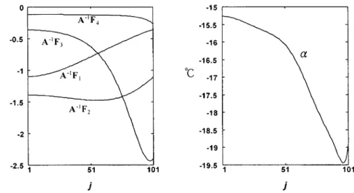
Following the design procedure, four columns of and the computed open-loop steady-state error, , are plotted in Fig. 3 for choosing . The computed steady-state tracking error, , is 19.4492 C. Since the most nonlinear
column of is , approximating by a
piecewise linear curve is most important. We thus choose .
The computed Hankel singular values of are .
Fig. 3. Four columns ofA F and open-loop steady-state error, .
TABLE I
SIMULATEDRESULTS FORDIFFERENTTRAJECTORIESWHENKANDG AREGIVEN IN(5.2)
for . With and starting from
, the design procedure gives
(5.2a)
and
(5.2b)
The value of the resultant is 32.3864, thus . To demonstrate the robustness of the PI controller (5.2), simulations are per-formed for three desired temperature trajectories: all start from 400 C but with three hold temperatures 1100 C, 1000 C and 1200 C beginning at . Convection effects
con-sidered include and
. The results are summarized in Table I which
in-cludes and
. It is clear that
is the most significant performance index for the temperature
controller. The second entry, ,
represents the damping behavior of the tracking error. The third
entry, , is used to compare with the
computed steady-state tracking error. The maximal tracking error during the entire heating process, , is less than 0.7 C for all these trajectories. Hence, the controller designed achieves good performance and robustness.
For all these cases, it turns that tracking error at
is very close to the computed steady-state tracking error, . When sensor noise is added to the simulation, roughly the same amount of sensor noise propagates to the tracking error.
We next consider a case where is not square. When the dimension of the reduced-order system is increased to six, the design procedure gives
(5.3a) and
Note that the entries of the gain matrices are much larger than that of the previous case. These control gains are also applied to these cases with different temperature trajectories. Simula-tions are performed with results shown in Table II. As the results show, the performance is close to that obtained in the previous case. Since the resultant and give a much higher value of
( while ),
the controller provides a faster response. The tracking errors are driven to steady state more quickly with a smaller peak,
.
VI. CONCLUSIONS ANDDISCUSSIONS
This paper proposes a method for RTP temperature control system design. The control system consists of a least square feedforward controller and a feedback controller. It is shown that for RTP systems with typical ramp-up and hold temperature profiles, a simple steady-state reduced order model is adequate for feedback design and very simple PI controller can be used to achieve good temperature tracking, uniformity, and robustness. A method for choosing good temperature sensor locations is also presented.
The design method prespecifies the feedback controller type (PI). With an appropriate choice of performance index, the de-sign reduces to the tuning of two parameters to quantitatively take dynamic performance and robustness into consideration. Systematic and simple tuning procedure is one attribute of the method that is different from RTP design methods proposed in the literature [3], [4], [6], [7], [16]. The simplicity of the PI controller, together with a simple tuning procedure, also makes on-line tuning possible, an advantage in real-time implementa-tion.
Thermal process of RTP, dominated by radiation and conduc-tion, exhibits highly damped and nonoscillatory dynamic re-sponse. It thus allows very accurate low-order approximation (the list of Hankel singular values in the example confirms this) and this in turn makes PI control suitable. In general the simplest (decentralized) -channel multiinput–multioutput (MIMO) PI controller requires tuning parameters if the channels are to be independently tuned. In the design example, there are only two parameters for a four-input–four-output system and they seem adequate. The reason is that, for the RTP system, the actuators are all of the same type (lamps) and the performance require-ment is dominated by uniformity, thus each channel is of the
same importance and hence only two parameters are required. The small number of tuning parameters makes the design ap-proach attractive.
ACKNOWLEDGMENT
The authors would like to thank the reviewers for their com-ments and suggestions which improved the paper.
REFERENCES
[1] R. B. Fair, Rapid Thermal Processing: Science and Technology. New York: Academic, 1993.
[2] P. Singer, “Rapid Thermal Processing: Progress Rep.,” Semiconductor International, May 1993.
[3] C. D. Schaper, M. M. Moslehi, K. C. Saraswat, and T. Kailath, “Mod-eling, identification, and control of rapid thermal processing sys-tems,” J. Electrochem. Soc., vol. 141, no. 11, pp. 3200–3209, Nov. 1994.
[4] C. D. Schaper, “Real-time control of rapid thermal processing semi-conductor manufacturing equipment,” in Proc. Amer. Contr. Conf., June 1993, pp. 2985–2989.
[5] C. D. Schaper, M. Moslehi, K. Saraswat, and T. Kailath, “Control of MMST RTP: Repeatability, uniformity, and integration for flexible man-ufacturing,” IEEE Trans. Semicond. Manufact., vol. 7, pp. 202–219, May 1994.
[6] J. D. Stuber, T. F. Edgar, J. K. Elliott, and T. Breedijk, “Model-based control of rapid thermal process,” in IEEE Proc. 33rd Conf. Decision Contr., Dec. 1994, pp. 79–85.
[7] S. Belikov and B. Friedland, “Closed-loop adaptive control for rapid thermal processing,” in Proc. 34th Conf. Decision Contr., Dec. 1995, pp. 2476–2481.
[8] C. D. Schaper, T. Kailath, and Y. J. Lee, “Decentralized control of wafer temperature for multizone rapid thermal processing systems,” IEEE Trans. Semicond. Manufact., vol. 12, pp. 193–199, May 1999.
[9] J. X. Xu, Y. Chen, T. M. Lee, and S. Yamamoto, “Temperature iterative learning control with application to RTPCVD thickness control,” Auto-matica, vol. 35, pp. 1535–1542, 1999.
[10] Y. K. Jan and C. A. Lin, “Lamp configuration design for rapid thermal processing systems,” IEEE Trans. Semicond. Manufact., vol. 11, pp. 75–84, Feb. 1998.
[11] Y.-K. Jan, “Lamp Configuration and Control System Design for Rapid Thermal Processing Systems,” Ph.D. dissertation, Nat. Chiao-Tung Univ., Hsinchu, Taiwan, R.O.C., 2000.
[12] K. Zbou, F. C. Doyle, and K. Glover, Robust and Optimal Con-trol. Englewood Cliffs, NJ: Prentice-Hall, 1995.
[13] B. A. Francis, Lecture Notes in Control and Information Sci-ences. New York: Springer-Verlag, 1987.
[14] T. Kailath, Linear Systems. Englewood Cliffs, NJ: Prentice-Hall, 1980. [15] H. A. Lord, “Thermal and stress analysis of semiconductor wafers in a rapid thermal processing oven,” IEEE Trans. Semicond. Manufact., vol. 1, pp. 105–114, Aug. 1988.
[16] P. P. Apte and K. C. Saraswat, “Rapid thermal processing uniformity using multivariable control of a circularly symmetric 3 zone lamp,” IEEE Trans. Semiconduct. Manufact., vol. 5, pp. 180–188, Aug. 1992.
Ching-An Lin received the B.S. degree from the
National Chiao-Tung University, Taiwan, R.O.C., in 1977, the M.S. degree from the University of New Mexico, Albuquerque, in 1980, and the Ph.D. degree from the University of California, Berkeley, in 1984, all in electrical engineering.
He was with the Chung-Shan Institute of Science and Technology from 1977 to 1979, and with Inte-grated Systems Inc. from 1984 to 1986. Since June 1986, he has been with the Department of Electrical and Control Engineering, the National Chiao-Tung University, Taiwan, where he is a Professor. His current research interests in-clude multivariable control and signal processing.
Yaw-Kuen Jan received the B.S. degree in electrical
engineering from the National Taiwan University, Taiwan, R.O.C., in 1986, and the M.S. degree in control engineering from the National Chiao-Tung University (NCTU), Taiwan, in 1990.
Since 1990, he has been a Vice-Engineer in the Chung-Shan Institute of Science and Technology. He is currently pursuing the Ph.D. degree in control en-gineering at NCTU, and his research interests are in lamp configuration design and temperature control in rapid thermal processing.