Object Coverage with Camera Rotation in Visual
Sensor Networks
Tzung-Shi Chen Chih-Ping Chen
Dep. of Computer Sci. and Information Eng. National University of Tainan
[email protected], [email protected]
Hua-Wen Tsai
Dep. of Computer Info. and Network Eng. Lunghwa University of Science and Technology
[email protected] Abstract ― In this paper, an object coverage algorithm in
visual sensor networks is proposed. When sensors equipped camera with rotating capability in the moni-toring environment are deployed randomly, the images of target object with circle shape may be captured by dif-ferent camera nodes in difdif-ferent orientations at the same time. In order to achieve the full coverage of objects, there might be lots of redundant image data to consume the transmission energy in visual sensor networks. An approach is proposed to solve this problem. It is tried to reduce the cover set of camera nodes by rotating camera of sensors. Such set can cover the maximum angle of view of the object. In addition, a mapping is proposed for find out the coverage problem for target objects with convex polygons. Therefore, by applying the proposed algorithm, cameras can capture images of the convex polygon object in terms of circle. The simulation results show that our approach can reduce the number of sensors while pre-serving the maximum coverage range of object.
Index Terms―angle of view, camera node, convex
poly-gon, object coverage, visual sensor networks.
I. INTRODUCTION
A visual sensor networks (VSN) consists of tiny visual sensor nodes called camera nodes, which integrate the image sensor, embedded processor, and wireless transceiver [9]. In VSN, all sensor nodes are equipped with cameras and they are re-sponsible for capturing the images of the target [3]. VSNs also provide some high-level services to the user so that the large amount of data can be dis-tilled into information of interest using specific queries [4].
Unlike general sensor networks, the covered range of visual sensors is determined by the cam-eras' field-of-view (FOV) instead of sensing range [3]. Thus, camera nodes can just partially cover objects. Another difference between visual sensor
networks and other types of sensor networks is the nature and volume of information the individual sensors acquire. Unlike most sensors, cameras are directional in their field of view, and they capture a large amount of visual information which may be partially processed independently of data from other cameras in the network.
In VSNs, we are more interested in the im-age/vision data than scalar data. There are many applications for VSNs [1] [9]. Due to the limited power resources, it is beneficial to select a mini-mally sufficient subset of sensors to preserve the coverage while reducing energy consumption. However, in VSNs, camera sensors generate a huge amount of data compared to scalar sensors. Processing and transmitting such data by generally low-power sensor nodes is challenging due to their computational and bandwidth requirements [1]. In [5] [7], the authors also showed that message transmission is the major source of energy dissipa-tion in sensor networks. Thus, our goal is to achieve the full coverage of objects by selecting a suitable cover set of camera nodes. A suitable cov-er set is a set which contains as few camcov-era nodes as possible to be able to cover the entire object. Only the data of selected cover set needs to be transmitted to the sink so that it can avoid trans-mitting the redundant data. It can save energy covers the whole object in using the minimum cover set.
The object coverage problem in visual sensor networks is investigated. An object is monitored by several camera nodes surrounding it in a moni-toring environment. The monimoni-toring environment can be in a parking space, forest, lake and so on. Many papers on object monitoring assume that the
object of interest can be covered by one single sensor, but it is not reasonable in VSNs. Our ob-jective is to make sure that the perimeter of object which we concern is completely covered by the sensors. The problem is defined as angle coverage since the portion of perimeter covered by a sensor is in terms of angle. If there are many camera nodes in the monitoring area, it is easy to preserve full coverage of object by combining the data that all camera nodes transmit to sink. However, it is not an energy efficient approach as the heavy transmission load will drain the batteries of sen-sors quickly. In order to save energy, the data should be collected selectively.
Minimizing the amount of data transmission can help prolong the network lifetime. In [2], Chow, Lui, and Lam defined the Minimum Cover problem as identifying a set of sensors which pre-serve full angle coverage with minimum number of sensors. However, they can not rotate cameras of camera nodes to cover the extension of objects. Hence, a Rotating Camera Coverage algorithm (RCC) which aims at getting complete angle cov-erage with minimum cover set by rotating cameras of camera nodes is proposed here. By fulfilling the greedy-based algorithm, RCC, nodes will be se-lected as large coverage as possible into the mini-mum cover set. The scalable coverage can be ex-tended forward or backward by rotating the cam-era. The best node into minimum cover set will be selected until the object can be fully covered. Fur-thermore, the coverage problem of convex poly-gon is studied as well. A mapping is addressed to map an arbitrary convex polygon into a circumcir-cle. In simulation, the number of sensors in terms of RCC compared with the previous work [2] is reduced.
The rest of this paper is organized as follows. In Section II, the related work about coverage prob-lem is reviewed. Section III is the probprob-lem state-ment and network model in this paper. In Section IV, the proposed algorithms are described. In Sec-tion V, the simulaSec-tion results are presented. Finally, Section VI concludes this work.
II. RELATED WORK
In visual sensor networks, coverage problem is
an important research issue which is concerned with how an object or an area is monitored by sensors.
Soro and Heinzelman [8] studied the coverage problem in video-based sensor networks. Video cameras have the unique feature of capturing im-ages of objects. Objects are not necessarily near the cameras. Hence the objects which are covered by the camera can be far from the camera. In vid-eo-based sensor networks, the sensing range of sensor nodes is replaced with camera's field of view (FOV). In this work, it is assumed that all the camera nodes are mounted on a plane and they are directed towards the service plane. The simulation results showed that because of the unique way that cameras capture data, the traditional algorithm does not give expected results in terms of coverage preservation. However, in a visual sensor network, it is not common that all the cameras monitor the area in one plane as the case in [8]. Generally speaking, the sensors are distributed randomly in the network with arbitrary orientations.
In [2] [3], Chow et al. focused on the perimeter coverage problem. They considered a tracking system where an object of interest is monitored by sensors surrounding it. The portion of the target's perimeter covered by a sensor is expressed in terms of angle. Their objective is to preserve the full angle coverage and maintaining the target's perimeter being completely covered.
Though Chow et al. proposed the FIND_MIN_COVER algorithm to identify mini-mum set of sensors, they assumed the object is circular and the sensor nodes which equipped with stationary cameras. In our work, in order to cover the extension of objects and to preserve the full angle coverage with minimum number of sensors, A Rotating Camera Coverage algorithm (RCC) is proposed. It allows camera nodes rotate cameras arbitrarily. We also study the coverage problem of convex polygon. The arbitrary convex polygon which can be mapped into a circumcircle is dis-cussed. Therefore, by fulfilling RCC, we can also monitor the convex polygon with full angle cov-erage.
III. NETWORK MODEL AND PROBLEM S TATE-MENT
Assumptions, network model, problem state-ment for the coverage, and the coverage problem for arbitrary convex polygon will be discussed in this section.
A. Assumptions
In this paper, there are the following assump-tions: (1) The object is circular and static; (2) Cameras are adjusted to the suitable focal distance; (3) Camera nodes are randomly distributed and static in the network; (4) Cameras can rotate 360° to cover the object; (5) Object and each camera node know their physical locations.
Because camera nodes are deployed randomly, only camera nodes which are around the object with appropriate distance and orientation can cap-ture images of the object. In order to view the en-tire object, gathering all the images from the sur-rounding sensors is an intuitive idea. However, the camera nodes may be close to each other in the monitoring area and thus the captured images are highly correlated. Hence, sending all the images to the sink will waste a lot of energy.
In Figure 1, the shaded circle means the ob-ject to be monitored. Camera nodes are represented by the little circles with different col-ors. Each camera node is assigned a unique num-ber. The sets of coverage, {4, 6, 10, 13, 17, 21} and {6, 10, 13, 17, 21} are able to preserve all the perimeter of object. It is easy to see that node 4 is a redundancy which can be removed.
Figure 1: Monitoring environment with camera nodes B. Covered Range
Chow, Lui, and Lam [3] described that covered range is defined as the portion of perimeter of the object covered by a sensor node. In our work, we also represent the covered range in terms of angle.
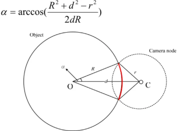
The ranges of the perimeter of the object can be identified by camera nodes. In Figure 2, we show that how a camera node obtains its covered range if the object is circular with a radius R. Addition-ally, 2α is the covered angle, r is the sensing range of the camera node, and d is the node distance between the object and the camera node. Since every camera node is aware of its physical location, the value of d can be acquired. Then, the covered angle can be calculated by using the Cosine Law as the following equation:
) 2 arccos( 2 2 2 dR r d R (1)
Figure 2: The covered range of the object
Figure 3 shows that the different distance be-tween the object and the camera node can affect the covered range while d1 and d2 are represented
as the distances between the camera-node and the center of the object. Covered range is equivalent to the angle of view captured by camera-nodes. Thus, the longer node distance makes the larger captured range. Similarly, under the same node distance, the larger the FOV, the larger the captured range is.
Figure 3: Different distances between the object and the camera node
C. Camera Rotation
In order to cover the portion of the object not covered by any other camera nodes first, we as-sume cameras can rotate their angles. If a camera has FOV (θ), for most of cases the covered range will become larger while rotating cameras either clockwise or counterclockwise except for some
cases. We define Φ° as the angle of rotating cam-era. Besides, si and ti are the start radian of covered range on the object and the end radian of covered range on the object, respectively. After cameras rotating, si becomes si(Φ) and ti becomes ti(Φ). We also describe the lemmas as follows. Throughout this paper, we omit the proof for all of lemmas due to paper length limitation.
Lemma 1: If both the extended lines of FOV of
camera are exactly secant to the circular object, the first two intercross points which are formed by two secant lines will be a chord. The chord is the smallest chord than any other chords generated by the same camera node.
Lemma 2: If all cameras have the same FOV (θ)
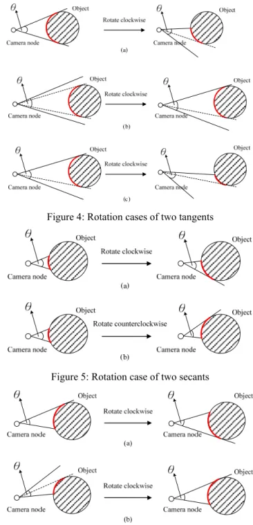
and when they illuminate the object exactly with-out the cases of two tangents (both the extended lines of FOV of camera are tangent to the circular object), the covered range will become larger while rotating cameras clockwise or counter-clockwise.
In what follows, we analyze seven situations of coverage while rotating cameras. As the case in the left-hand side in Figure 4(a), both the extended lines of FOV of camera are exactly tangent lines to the object. But after rotating camera clockwise, the covered range becomes smaller. Owing to the changes of orientation of the camera, the right graph of Figure 4(a) shows that the camera node can just cover a small portion of the object in its FOV. In the left-hand side of Figure 4(b), the node distance is longer than that in Figure 4(a) so that both the extended lines of FOV of camera are away from the object. When both the extended lines of FOV of camera are away from the object which locates in the FOV of camera, it is the same as the case of exactly tangent lines to the object. Therefore, we will not rotate the camera as the case in the left-hand side of Figure 4(b) since the covered range is the same as the right graph of Figure 4(b). As mentioned above, we will not ro-tate camera as the case in the left-hand side of Figure 4(c).
In Figure 5, both the extended lines of FOV of camera are secant lines to the object. We can see that in the same conditions but node distance, the covered range with two secants is smaller than it
with two tangents. Thus, in the left-hand side of Figure 5(a) and the left-hand side of Figure 5(b), rotating camera clockwise or counterclockwise to make covered range become larger is helpful. Af-ter rotating cameras as in Figure 5, the extended lines of FOV of camera are one tangent and one secant. Then, it is not necessary to go on rotating the camera because the covered range will not be increased.
Figure 4: Rotation cases of two tangents
Figure 5: Rotation case of two secants
Figure 6: Rotation cases of one tangent and one secant
shown in Figure 6. When the extended lines of FOV of camera are exactly tangent and secant to the object, we may rotate the camera to another direction to cover another portion of object. In the right-hand side of Figure 6(a), the covered range is the same as that in the left-hand side of Figure 6(a) because the object is circle. The case as in Figure 6(b) is good for rotating since the covered range can be expanded and the original covered portion of the object does not change. Consequently, the covered range in the right-hand side of Figure 6(b) becomes larger than that in the left-hand side of Figure 6(b).
As the three cases illustrated in Figure 4, cam-eras will not be rotated since the covered range will not be expanded. Additionally, if both ex-tended lines of FOV of camera are tangent lines to the object, the covered range is the maximum. In Figure 5, if the extended lines of FOV of camera are two secants to the object, rotating to the status with one tangent and one secant is the maximum covered range. In Figure 6, after rotating cameras, the extended lines of FOV of camera may cause two conditions: one tangent and one secant or two tangents as shown in Figure 4. The covered range is affected by rotating camera; therefore, cameras are rotated to cover a certain portion of the object if it can cover.
D. Problem Statement
Due to the rotation of cameras, each portion of perimeter of the object covered by a camera node may increase or decrease after cameras rotating. In our point of view, rotating a certain camera node may cause another camera node become redundant. Then, the redundant node can be removed so that the cover set become smaller. On the other hands, if there is a gap between capture ranges, rotating cameras may solve this problem. We name the problem of finding Minimum cover Set by Rotat-ing Camera as MSRC problem and it is defined as follows:
Definition 1: (Minimum Cover Set) Given a set
of sensors S, let the covered range of sensor node i
S be V(i) = [si, ti]. If ti < si , sensor i covers 0°
of the perimeter. A set D S is a cover if for each angle γ [0°, 360°], there exists a sensor i in D such that γ [si, ti]. UiDV(i) = [0°, 360°].
A set F S is a minimum cover set if it is the smallest in size among all the possible sets of
sen-sors which preserve the widest angle coverage.
□
Definition 2: (MSRC Problem) The MSRC
prob-lem is to find out the minimum cover set which is defined by rotating cameras, and how to select the first node into the minimum cover set. □
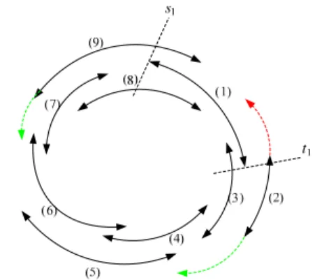
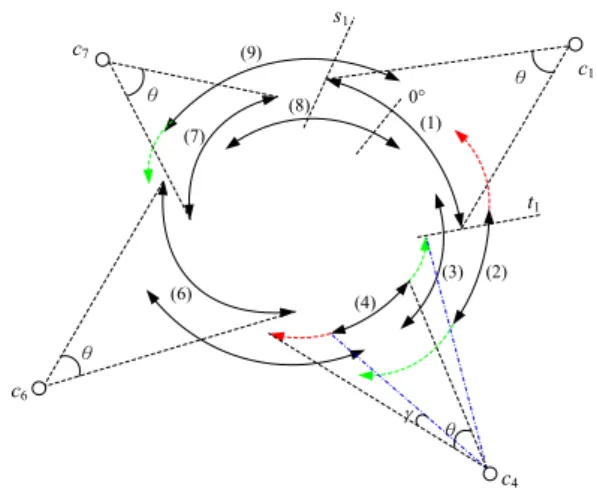
In Figure 7, we suppose 9 camera nodes sur-rounding an object, and each arrow represents the covered range of one node. We assume the start angle of Node 1 is s1, and the end angle of Node 1
is t1. The green arrow means the covered rang
which can increase by rotating camera. The red arrow means the covered range which will de-crease after rotating camera. Without rotating cameras, let Node 1 be the first selected node and searching clockwise, {1, 3, 4, 6, 7, 9} can be iden-tified by applying the FIND_MIN_COVER algo-rithm which Chow et al. proposed. But in this Fig-ure, after rotating cameras by applying our RCC algorithm, the minimum cover set will be {1, 2, 5, 6, 9} which just contains 5 nodes.
Figure 7: Minimum cover set with camera rotation E. Integer Programming
According to the MSRC problem we have de-fined above, it can be formulated as integer pro-gramming (IP) constraints as follows.
Given:
N sensor nodes: Ci , i=1,2,…N, C: the cover set of all sensors, A: the subset of C,
θ: the initial angle of FOV,
Variables:
ti°: the end radian of covered range on the object
Φ°: the angle of rotating camera, 0°≦Φ°≦360° si(Φ)°: the rotated start radian of covered range on the object
ti(Φ)°: the rotated end radian of covered range on the object
k: the number of set A
Ak: the covered range by camera
cover (Ak): the coverage summation of Ak
a: if sensors can capture the object, then a is 1,
else 0 Objective: cover(A )k 360° Subject to: (1)
N n n nx
a
1 360° (2) 1k 2 n (3) xk ti si 180°, if si(Φ) < ti(Φ), xk Ak, 0 ≦Φ≦ 360° (4) xk ti 360°si 180°, if si(Φ) > ti(Φ), k k A x , 0 ≦Φ≦ 360° (5) cover (A ) = k n k N n n nx
x
A
a
,
1Based on constraints (1) and (2), we can know that to solve the MSRC problem is an NP-complete problem. Consequently, the Rotating Camera Coverage algorithm (RCC) we proposed to solve this problem is discussed in Section IV.
F. Convex Polygon
In this subsection, we study the coverage prob-lem of convex polygon. We define the arbitrary convex polygon which can be mapped into a cir-cumcircle. Therefore, by fulfilling RCC, we can also monitor the convex polygon with full angle coverage. We assume the location of the center of the circle is known, and so is each vertex of the convex polygon. In Figure 8, the object is represented by shaded convex polygon which is covered by camera nodes, and the red arcs represent its covered range. Because of the rela-tionship between camera orientation and the edge of convex polygon, we assume that the captured images would be clear when the included angle
between camera orientation and edge of convex polygon is more than Ψ or equal to Ψ, where Ψ = 20°. In most cases, the visible angle of LCD mon-itors is 140°, thus we suppose (40/2)° to be the right or the left visible angle in this paper. Other-wise, the vectors in Figure 8 which start form the center of circle “O” to intercross the arc of the cir-cle. Thus, the red points on the convex polygon can be mapped to the red point on the arc of the circle. By Lemma 3, we can find a circle to contain entire convex polygon. Lemmas 4 and 5 are to ex-plore the relationship between the points on an ar-bitrary convex polygon and the points on the cir-cumcircle.
Figure 8: The coverage of convex polygon
Lemma 3: There is a circle exists to contain an
arbitrary convex polygon.
Lemma 4: There is a “one-to-one” relationship
between the points on an arbitrary convex polygon and the points on the “minimum” circle.
Lemma 5: There is a “onto” relationship between
the points on an arbitrary convex polygon and the points on the “minimum” circle.
IV. ROTATING CAMERA COVERAGE A LGO-RITHM
As mentioned above, rotating cameras to select the minimum cover set may have two advantages: make the minimum cover set become smaller and the gap problem can be solved. Since Pottie and Kaiser proved that message transmission is the major source of energy dissipation in sensor net-works [6], to keep the loading of transmission down is necessary. Hence, Chow et al. developed the Minimum Cover algorithm,
and where , Minn 2 k 1 C A Ak k
FIND_MIN_COVER, to identify a set of sensors which preserve the widest angle coverage with minimum number of data to be sent. However, they can not rotate cameras of camera nodes to cover the extension of objects. Therefore, we pro-posed Rotating Camera Coverage algorithm (RCC) which aims at getting complete angle coverage with minimum cover set by rotating cameras. Due to the difficulty of NP-Complete problems, our algorithm, RCC, is a kind of heuristic algorithms.
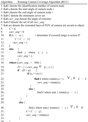
A. Centralized Algorithm
Algorithm: Rotating Camera Coverage Algorithm (RCC) 1: Let i denote the identification number of camera node 2: Let si denote the start angle of camera node i
3: Let ti denote the end angle of camera node i
4: Let C denote the minimum cover set 5: Let curr_ang denote the angle of criterion 6: Let D denote the set of all curr_ang
7: Let sec denote the extended lines of FOV of camera are secant to object 8: C = φ
9: curr_ang = 0
10: if (ti < si) { // determine if covered range is across 0° 11: C = C ∪ {i} 12: curr_ang = ti 13: } 14: else { 15: find j where tj ≧ ti 16: curr_ang = tj 17: } 18: where (curr_ang < 360) { 19: D = { i | curr_ang [si , ti ) } 20: if (D = φ) { 21: if (sk ==sec) {
22: find k where rotate(sk) = ti ,i S - C
23: curr_ang = rotate(tk)
24: }
25: else {
26: find k where min { rotate(sk) - ti }
27: }
28: }
29: else {
30: find j where max{ rotate(tj) - ti } i D
31: C = C ∪ {j} 32: curr_ang = rotate(tj)
33: }
34: }
Figure 9: Rotating Camera Coverage Algorithm
In Figure 9, algorithm RCC is proposed. We in-itiate the minimum cover set C as empty, and the
current_angle is set to be 0°. We determine if there
is any covered range spans across 0°. If there is no covered range to span across 0°, we will choose the node with largest covered range as the first node and then continue selecting the next node clockwise or counterclockwise. Otherwise, we will choose all the covered range spans across 0° as the first node. We will not rotate the first node even if
it is allowed to rotate. Assume a camera node k is selected, so that current_angle will be set to tk.
Thus, when the first node is identified, the
cur-rent_angle is set to be the end angle of that node.
We select the next node by comparing the covered range of three cases as follows.
Case 1: A neighbor j of k that has largest tj, and
the camera of tj can not rotate, thus the covered range will not be changed.
Case 2: A neighbor j of k that the camera of tj can
rotate to extend the covered range and its covered range can also connect with the previous covered range.
Case 3: The covered range of node j which does
not connect with the selected covered range can extend backward to connect the previous covered range by rotating camera, and its end angle, tj, will not change.
When the first node is selected and then after comparing the three cases of rotating, the covered range with maximum tj will be the second node, and its end angle is set to be the current_angle. The process will continue until the current_angle is more than or equal to 360°. For the example in Figure 10, the green arrow means the covered rang which can increase by rotating camera. The red arrow means the covered range which will de-crease after rotating camera. Each FOV is set to be θ, and γ is the rotating angle of c4 (also Node 4). Due to the covered range of Node 1 and Node 8 span across 0°, there are four cover sets will be found by fulfilling RCC. We choose Node 1 to be the first node and then search clockwise and coun-terclockwise respectively to identify two cover sets. Another two cover sets are generated by choosing Node 8 as the first node, and we also search clockwise and counterclockwise. After ro-tating, we can identify {1, 2, 5, 6, 9}, {1, 9, 6, 4, 2}, {8, 1, 2, 5, 6, 9} and {8, 7, 6, 4, 3, 1}. Ob-viously, {1, 2, 5, 6, 9} and {1, 9, 6, 4, 2} are min-imum cover sets. However, when searching clockwise in {1, 2, 5, 6, 9}, Node 2 and Node 9 are rotated, and we only rotate Node 9 with searching counterclockwise in {1, 9, 6, 4, 2}. Therefore, {1, 9, 6, 4, 2} is the optimal minimum cover set.
(1) (2) (3) (4) c4 (6) (7) (8) (9) s1 t1 0° θ θ θ c6 c7 θ c1
Figure 10: Covered range span across 0° B. Distributed Algorithm
Our distributed version of RCC is based on FIND_MIN_COVER. The main difference be-tween RCC and FIND_MIN_COVER is the rota-tion of cameras. In the distributed algorithm, each sensor needs to obtain the covered range of their neighbors only. That is, if the covered range of sensor i is [si, ti], i knows the covered range of neighbor j if si ≦ sj ≦ ti or si ≦ tj ≦ ti. Ac-cording to the example in Figure 10, node c1
knows the covered ranges of neighboring nodes c2,
c3, c8, and c9. At first, we describe how a node
knows whether it is in a minimum cover set or not. After getting the covered ranges from neighbors, a node ck will determine whether it is in a minimum
cover set. Then, node ck checks whether it fulfills
either one of the two following conditions: (1) node ck covers an angle that is not covered by
oth-ers, or (2) node ck does not have any backward
neighbor and tk is largest among all its neighbors. After knowing that node ck itself is in a minimum
cover set, it announces to its neighbors that it is selected and then starts to identify the next sensor.
Based on RCC, when node ck is selected, the
current angle will be set to be tk. The next node to be included should be a neighbor j of k that has largest tj. However, node ck can identify j with its
local information of neighborhood, and it will then notify node cj by sending a selected message.
Hence, the selected node can find the next node accordingly. Other neighbors of k who can over-hear the message to j would also aware that they are not selected.
V. SIMULATION
We present the simulation result of our algo-rithm by using C++. We study the performance of RCC under the scenario of visual sensor networks. We also compare the performance between RCC and FIN_MIN_COVER. Then we describe the si-mulation results with different parameters.
A. Simulation Environment
In our simulation environment, the whole net-work area is set to be 26 × 26 grids. We assume the width of each grid is one unit distance, and there is at most one camera node in one grid. The orienta-tions of all camera nodes and its locaorienta-tions are as-signed randomly. Due to camera nodes are dep-loyed randomly, the probability that a grid has a node depends on the density. We use 0.6 as the probability, and the radii of the object which is as-sumed to be circular are 4, 5 and 6. The object lo-cated at (12, 12) and the node distance is between 8 and 13. We define “node distance” as the dis-tance between camera node and the center of cir-cular object. If the node distance is out of the range we set, we will not consider that node. We also consider the FOV of cameras as 20, 30, 40 degrees and 330 nodes are deployed in the grid to monitor the object.
We prefer to rotate the camera nodes with the extended lines of FOV secant to the object. We make the table of our parameters as follows.
B. Simulation Results
FOV = 20, Radius = 5
Angle of Coverage (degree)
160 180 200 220 240 260 280 300 320 340 360 380 Mi n imu m Cov e r No de s 20 25 30 35 40 45 50 55 RCC FIND_MIN_COVER
Figure 11: The performance with FOV = 20 and r = 5
In Figure 11, we compare RCC and FIND_MIN_COVER with seven different angle of coverage, and the FOV of all camera nodes are 20,
the radius of the object is 5. Each point in the fig-ure represents the average value of minimum cov-er nodes. The black line with black points is the simulation results of RCC, and the dotted line with white points is the simulation results of FIND_MIN_COVER. We use ceiling functions to map a real number to the next largest integer. Thus, the minimum cover nodes are showed by integers not decimals. In each angle of coverage 180, 210, 240, 270, 300, 330 and 360 (degree), we run RCC and FIND_MIN_COVER 100 times to generate the numbers of minimum cover nodes with the same parameters. The results show that using RCC can decrease the numbers of minimum cover nodes. On the other hands, the more angle of cov-erage we want to cover, the more camera nodes which can cover the object we need.
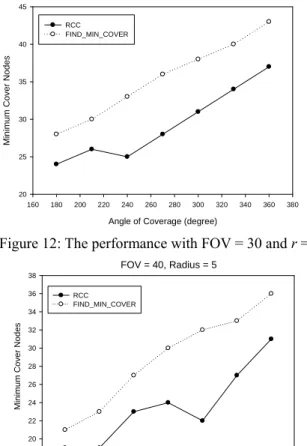
In Figures 12 and 13, we adjust the FOV of cameras to be 30 and 40 respectively. It can be found that if the radius of the object is invariable, as the FOV increases, the numbers of minimum cover nodes decrease.
FOV = 30, Radius = 5
Angle of Coverage (degree)
160 180 200 220 240 260 280 300 320 340 360 380 Mi nimu m Co ver N ode s 20 25 30 35 40 45 RCC FIND_MIN_COVER
Figure 12: The performance with FOV = 30 and r = 5
FOV = 40, Radius = 5
Angle of Coverage (degree)
160 180 200 220 240 260 280 300 320 340 360 380 Minim u m Cov e r Nodes 18 20 22 24 26 28 30 32 34 36 38 RCC FIND_MIN_COVER
Figure 13: The performance with FOV = 40 and r = 5
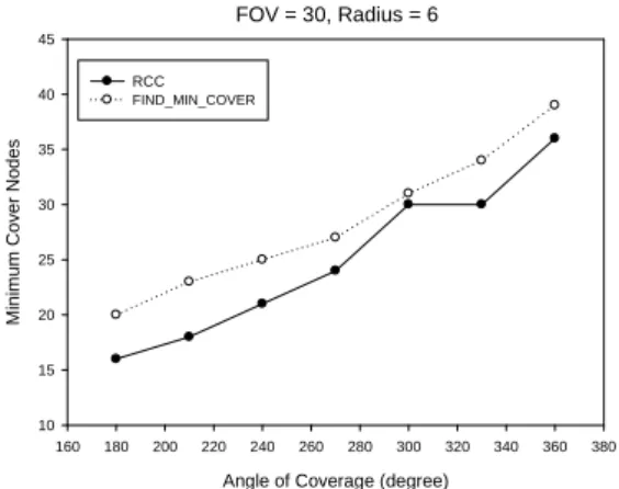
In Figures 14 and 15, we set the FOV as 30 and the radii of the object are 4 and 6 respectively. In different radius of the object, the larger radius of the object makes more requirements of camera nodes. Although the size of object becomes large, the simulation results show that the performance of our algorithm, RCC, is better than the FIND_MIN_COVER. Thus, we can efficiently define the minimum cover set by applying RCC.
VI. CONCLUSIONS AND FUTURE WORK
In order to identify the minimum cover set of sensors, the algorithm, Rotation Camera Coverage algorithm (RCC) was proposed. In addition, the coverage problem of convex polygon has been discussed. The arbitrary convex polygon can be mapped into a circumcircle. Therefore, by fulfil-ling RCC, we can also monitor the convex poly-gon. We also state the problem of finding Mini-mum cover Set by Rotating Camera as MSRC problem, and according to the MSRC problem, it can be formulated as integer programming (IP) constraints. The results showed that using RCC can decrease the numbers of minimum cover nodes. On the other hands, the more angle of cov-erage we want to cover, the more camera nodes which can cover the object we need. The simula-tion results also showed that the performance of our algorithm, RCC, is better than the FIND_MIN_COVER. In the future, we will take the energy consumption into account, and try to solve the handoff problem in terms of object movement in visual sensor networks.
FOV = 30, Radius = 4
Angle of Coverage (degree)
160 180 200 220 240 260 280 300 320 340 360 380 Mi n imum Cov e r Node s 14 16 18 20 22 24 26 28 30 RCC FIND_MIN_COVER
FOV = 30, Radius = 6
Angle of Coverage (degree)
160 180 200 220 240 260 280 300 320 340 360 380 Mi ni mu m C o v e r N o des 10 15 20 25 30 35 40 45 RCC FIND_MIN_COVER
Figure 15: The performance with FOV = 30 and r = 6
ACKNOWLEDGES
This work is supported in part by National Science Council under grant no. NSC-98-2221-E-024-008, Taiwan.
REFERENCES
[1] I. F. Akyildiz, T. Melodia, and K. R. Chowdhury, "A survey on wireless multimedia sensor networks,"
Com-puter Networks, vol. 51, no. 4, pp. 921-960, Mar. 2007.
[2] K.-Y. Chow, K.-S. Lui, and E. Y. Lam, "Maximizing angle coverage in visual sensor networks," in IEEE
In-ternational Conference on Communications, Glasgow,
UK, pp. 3516-3521, Jun. 2007.
[3] K.-Y. Chow, K.-S. Lui, and E. Y. Lam, "Wireless sensor networks scheduling for full angle coverage," in
Multi-dimensional Systems and Signal Processing, vol. 20,
is-sue 2, pp. 101-119, Jun. 2009.
[4] K. Obraczka, R. Manduchi, and J. J. Gar-cia-Luna-Aveces, "Managing the information flow in visual sensor networks," in Proceedings of 5th
Interna-tional Symposium on Wireless Personal Multimedia Communications, vol. 3, pp. 1177-1181, Honolulu,
Ha-waii, USA, Oct. 2002.
[5] G. J. Pottie and W. J. Kaiser, "Wireless integrated net-work sensors," in Communications of the ACM, 2000, vol. 43, issue 5, pp. 51-58, May 2000.
[6] K. Romer, and F. Mattern, "The design space of wireless sensor networks," IEEE Wireless Communications, vol. 11, issue 6, pp.54-61, Dec. 2004.
[7] V. Raghunathan, C. Schurgers, S. Park, and M. B. Sri-vastava, "Energy aware wireless microsensor networks," in IEEE Signal Processing Magazine, vol. 19, issue 2, pp. 40-50, Mar. 2002.
[8] S. Soro and W. Heinzelman, "On the coverage problem in video-based wireless sensor network," in Workshop on
Broadband Advanced Sensor Networks, Boston, MA,
USA, vol. 2, pp. 932-939, Oct. 2005.
[9] S. Soro and W. Heinzelman, "A Survey of Visual Sensor Networks," Advances in Multimedia, vol. 2009, Article ID 640386, 21 pages, 2009.