Dye-Sensitizer Solar Cells
國立高雄大學化工及材料系
楊乾信
太陽能電池
太陽光→ 材料 → 電能
(光子,Photon) (電勢,Electricity)
Photovoltaic device
標準太陽光模擬器照射下太陽電池的效率
分析
傳統太陽電池製作方法
方法 特徵 應用材料 現況 直拉法 1.得單晶 2.成本高 單晶矽 量產 鑄錠法 1.成本低 多晶矽 量產 塗佈燒結法 1.簡單 2.厚與品質難 控制 CdS/CdTe 小批量 電沉積法 1.簡單 2.水污染 CdS/CdTe 小批量 双源沉積法 1.組成易控制2. 設備複雜 CdS/CuInSe2 開發中 CVD法 1.設備簡單 2.品質難控制 多晶矽、非晶 矽、GaAs 小批量2004年全球前十大太陽能元件廠商
排 名
廠 商
國 別
佔有率
1
SHARP
日本
21%
2
BP Solar
英國
8%
3
京 瓷
日本
8%
4
Shell Solar
荷蘭
7%
5
三菱電機
日本
7%
6
三 洋
日本
7%
7
Q-Cells
德國
5%
8
RWE Schott Solar
德國
5%
9
Isofoton
西班牙
4%
(德國Sonnen, Bayern)
大型PV 發電系統
PV系統容量:1.7 MWp,集中設置
Inverter:18 個97 kW 市電併聯型Inverter
資料來源:工研院材料所德國Mont-Cenis玻璃屋拍攝,93年05月
太陽電池充電夾克
ScotteVest於CES展示了一件功能強大的夾克。整合了太陽能
面板,能用來給放在口袋中的移動電話、PDA、Game Boy、
MP3播放器及其他移動設備充電。2004年春該款夾克的零售
價將為300美元,不帶太陽能系統的款式則為200美元。
Mobile phone with PV power supply
A telephone booth supplied by photovoltaicswith an energy management system
有機太陽能電池的優點
及未來發展
優點
:
超薄
可以彎曲
可貼覆在大的面積上
低污染性
未來發展
:
提升光電效率
降低成本
Lifetime Costs EfficiencyFirst commercial DSC module produced by STI
(www.sta.com.au)
Courtesy Dr. WinfriedHoffman, CEO, RWE, SCHOTT Solar GmbH
各式DSSCs整體效率演進
染料敏化型太陽能電池 vs.光合作用
光合作用機制圖 染料敏化型太陽能電池
e
-e
-FTO Glass
Electrolyte
TiO
2with monolayer of dye
FTO Glass
Pt Catalyst
Counter electrode
Working electrode
染料敏化太陽電池結構
FTO glass FTO glassTiO2 with monolayer of dye
Electrolyte Pt Catalyst
實驗步驟
用Doctor blade method
製備薄膜電極
浸泡染料一天
覆上Platinum電極
並封裝
注入電解液
(0.1MLiI, 0.05MI2, 0.5MTBP/acetonitrile)
量測
溶膠凝膠法製備
Voc Vmax
Isc
效率提升-改善J
sc
,V
oc
,及F.F
Improvement of J
scA . TiO2 Photolectrode
Enhance the path length of the incident light ► Light-Scattering Effect Enlarging the surface area of the mesoscopic film ► Post-treatment Increase dye absorbed amount ► TiO2 surface area
Decrease recombination ► Barrier Layer (Coated with metal oxide)
B . Dye
Purity ► Develop Purification technology
Improvement of V
ocDecrease Dark Current ► Surface modification of Photoelectrode TiO2 Conducting band negative shift ► Additive like TBP ect.
Improvement of F.F
Decrease Series resistances ► TCO resistance,Pt electrode modification, Cell gap
Current Collection ► Pattern Design
TEM分析TiO
2
奈米結晶粒子
Fig. (a)原生粉末 (b)本實驗室粉末
A(101) R(101) A(200) A(105) A(101) R(101) A(200) A(105) (101) (112) (200) (211) Fig. (a)P25粉末 (b)本實驗製得之粉末繞射圖
(a)
(b)
X-光繞射圖譜(銳鈦礦結晶)
2-theta 20 30 40 50 60 70Int
ens
ity(
a.
u.
)
FTO TiO2 film (101) (004) (200) (105,211) (204)Raman shift (cm-1) 200 400 600 800 R am an int ensi ty ( a. u. ) TiO2 film A A A A A 2-Theta (degree) 20 30 40 50 60 70 In te n is ty (a .u .) FTO hydrothermal film (101) (112) (200) (105,211) (204)
14 13 12 11 10 9 8 7 6 5 4 3 2 1 ppm 2.490 3.422 3.439 4.695 6.889 6.909 7.152 7.172 7.202 7.220 7.372 7.390 7.409 7.491 7.512 7.732 2. 00 2. 11 6. 29 4. 29 2. 09 1. 03 13 14 ppm 14 13 12 11 10 9 8 7 6 5 4 3 2 1 ppm 2.482 2.486 2.491 2.495 2.499 3.311 4.721 7.149 7.171 7.211 7.229 7.285 7.304 7.322 7.445 7.465 7.484 7.621 7.643 7.817 4. 00 3. 63 2. 01 1. 07 1. 93 4. 08 2. 04 1. 46 14 13 12 11 10 9 8 7 6 5 4 3 2 1 0 ppm 2.491 3.347 4.635 7.238 7.260 7.663 7.685 7.820 6. 01 5. 98 5. 94 2. 95
Table 1. Maximum absorption data of the as-synthesized dyes.
a Absorption spectra of dyes measured in EtOH with the concentration of 5×10⁻⁵ M;
ε is the extinction coefficient at maximum absorption.
b Absorption spectra of dyes adsorbed on TiO
2 photo-electrode.
Dye ε,M λmax/nmUV a λmax/nmUV b
TPAR1 35264 455 460
TPAR2 44827 467 519
(HOMO) (LUMO) TPAR1 TPAR2 (HOMO) (LUMO) TPAR3 (LUMO) (HOMO)
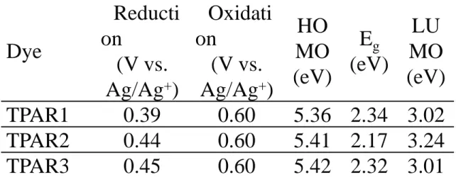
Table 2. Optical and electrochemical properties of TPAR dyes. Dye Reducti on (V vs. Ag/Ag+) Oxidati on (V vs. Ag/Ag+) HO MO (eV) Eg (eV) LU MO (eV) TPAR1 0.39 0.60 5.36 2.34 3.02 TPAR2 0.44 0.60 5.41 2.17 3.24 TPAR3 0.45 0.60 5.42 2.32 3.01
Wavelength (nm) 400 450 500 550 600 650 700 IP C E (% ) 0 10 20 30 40 50 60 70 80 90 TPAR1 TPAR2 TPAR3
Voltage (V) 0.0 0.1 0.2 0.3 0.4 0.5 0.6 J (m A cm -2 ) 0 2 4 6 8 10 12 14 16 TPAR1 TPAR2 TPAR3
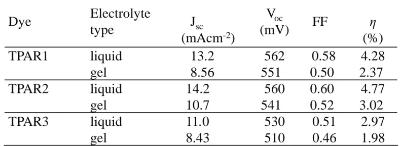
Table 3. Photovoltaic performance of DSSCs sensitized with as-synthesized TPAR dyes. Dye Electrolyte type Jsc (mAcm-2) Voc (mV) FF η (%) TPAR1 liquid gel 13.2 8.56 562 551 0.58 0.50 4.28 2.37 TPAR2 liquid gel 14.2 10.7 560 541 0.60 0.52 4.77 3.02 TPAR3 liquid gel 11.0 8.43 530 510 0.51 0.46 2.97 1.98
(TPA) (FTPA)
14 13 12 11 10 9 8 7 6 5 4 3 2 1 ppm 2.490 3.422 3.439 4.695 6.889 6.909 7.152 7.172 7.202 7.220 7.372 7.390 7.409 7.491 7.512 7.732 2. 00 2. 11 6. 29 4. 29 2. 09 1. 03 13 14 ppm
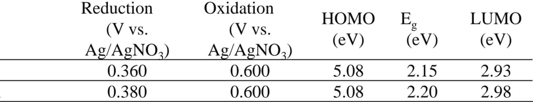
Table 1. Optical and electrochemical properties of TPAR and PTPAR dyes. Dye Reduction (V vs. Ag/AgNO3) Oxidation (V vs. Ag/AgNO3) HOMO (eV) Eg (eV) LUMO (eV) TPAR 0.360 0.600 5.08 2.15 2.93 PTPAR 0.380 0.600 5.08 2.20 2.98
Table Estimates of efficiency the effects from the 25-1 fractional factorial design with the defining relation I=ABCDE.
(薄膜厚度) (Pt電極的製備)
TiO2 film thickness( m) 5 10 E ff ici ency( % ) 0 2 4 6 8 Pt counter-electrode sputtered spin-coated E ff ici ency( % ) 0 2 4 6 8 10
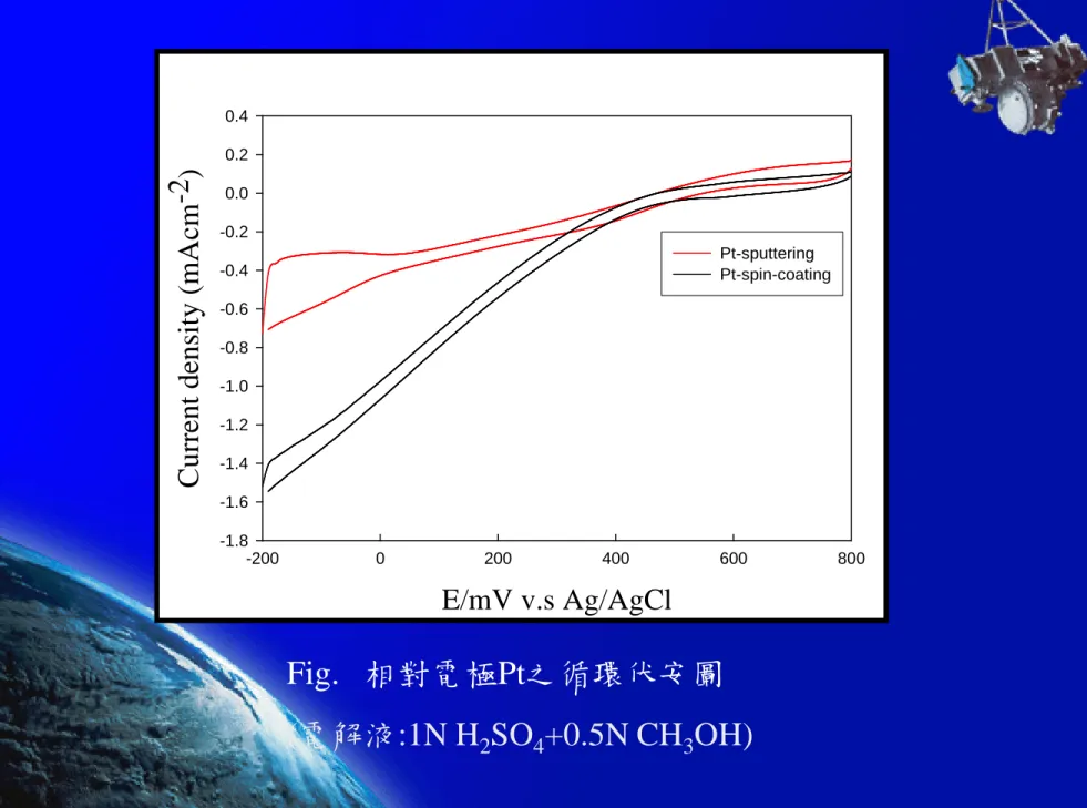
Fig. 相對電極Pt之循環伏安圖 (電解液:1N H2SO4+0.5N CH3OH) E/mV v.s Ag/AgCl -200 0 200 400 600 800 C ur rent dens it y ( m A cm -2 ) -1.8 -1.6 -1.4 -1.2 -1.0 -0.8 -0.6 -0.4 -0.2 0.0 0.2 0.4 Pt-sputtering Pt-spin-coating
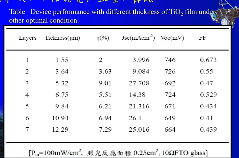
Table Device performance with different thickness of TiO2 film under other optimal condition.
最佳化條件,分別為FTO(10Ω)導電玻璃(A);15% PEG (B); MPN電解液(D);spin-coated Pt (E)
混合實驗設計法於染料敏化太陽能電池中的應用
Dye composition
Run x1(Adye) x2(Bdye) x3(Cdye) η(%) Jsc(mAcm-2) Voc(mV) FF
1 1 0 0 5.65 16.8 630 0.53 2 0 1 0 5.03 12.9 699 0.56 3 0 0 1 5.91 17.6 698 0.48 4 1/3 1/3 1/3 8.89 24.1 712 0.52 5 1/2 1/2 0 7.85 20.9 690 0.54 6 0 1/2 1/2 5.45 12.0 762 0.59 7 1/2 0 1/2 8.52 26.0 703 0.46 8 2/3 1/6 1/6 8.19 23.6 719 0.50 9 1/6 2/3 1/6 9.04 25.4 719 0.49 10 1/6 1/6 2/3 8.26 22.4 711 0.52 11 3/4 1/4 0 8.52 23.9 697 0.51 12 1/4 3/4 0 9.06 24.9 726 0.50 13 1/4 0 3/4 7.51 21.5 704 0.49 14 3/4 0 1/4 8.68 27.1 692 0.46 15 0 3/4 1/4 10.49 29.8 747 0.47 16 0 1/4 3/4 9.67 25.9 732 0.51
Table Design matrix and experimental results of A-B-C ternary dyes.
短路電流密度對染料組成之等高線圖
0.3
0.2
Fig. 效率對染料組成之等高線圖
0.3
0.5
Voltage(V) 0.0 0.2 0.4 0.6 0.8 Jsc (m A /c m 2 ) 0 5 10 15 20 25 30 35
Voc= 747mV
Jsc= 29.8mA/cm
2η = 10.4%
FF = 0.47
PUI的合成
Quasi-Solid State DSSCs
Voltage(V) 0.0 0.2 0.4 0.6 0.8 J( mA /cm 2 ) 0 10 20 30 40 1 2 3 4 6 7 5Sol-gel TiO2-N3 dye –CAN
(10% PUI-Mw300000)-Pt元件以 不同膜厚之J-V特性曲線圖
實境動態測試影片
1
混成式太陽光電與風力發電案例
資料來源:Renewable Energy The Solution to Climate Change,