切換式磁阻電動機驅動系統
之效率提昇策略
研究生:黃文楠 指導教授:鄧清政
國立交通大學 電機與控制工程學系
摘 要 論文中提出一新式之基於分析模式推導結論的切換式磁阻電動機驅動系統之效 率提昇策略,而此效率考量和控制方法乃由該電動機之模式而產生應用想法,其乃 於獲知等效磁化電感對時間之變化之下,藉著調置相電流命令與電壓間之比例而實 現其作動之功能;此效率提昇策略在本論文中經由探討後,構成實用上可行之效率 提升方法,其是運用此電動機參數間之連結關係而能於驅動之操作時,由設定之調 動規則,在不超過輸出性能需求所設定之範圍下執行命令,而經步階數值之更動, 調置電流命令值來搜尋驅動系統運作下可能存在的效率提昇數值。 在完整之效率提昇之控制架構中,考量等效磁化電感為電流與該馬達轉子轉動 位置之函數下,先採用模糊類神經網路來求算出電流、位置和該電感之映射關係, 再運用模糊類神經網路,近似地計算出與輸出轉矩相關之電感對位置偏微分量;此 外,數種需求之參數的新式估測和測量之架構與方法,包含有電阻值、電感值、互 感值、轉矩值和轉速值,亦於本論文中提出,而提供其與效率提昇架構之整合和合 併之可能考量;本論文也提出一類神經網路,在驅動系統未飽和運作下,乃為輸出 性能判斷之核心單元,而於高比例飽和運作之系統中,則與前述模糊類神經網路共 組性能判斷之雙核心。此外,於高性能切換式磁阻電動機驅動之考量下,二類就納 入電阻值變動或互感影響下之性能提升架構,亦運用電流補償之做法於此論文中進驗證所提出之相關論點之研究平台,乃針對可能運用於電動機車與洗衣機的切 換式磁阻電動機而組構二系統,其實驗與模擬結果皆部份驗證了所提出架構之效 能;此二式切換式磁阻電動機驅動系統實驗平台顯示了於五分之一,二分之一和全 載之額定功率下,在效率提升上分別展現了百分之三點五、百分之五和百分之七點 一,以及百分之三、百分之二點二和百分之五點一的效率提昇程度。
An Efficiency Improvement Strategy for Switched
Reluctance Motor Drives
Student: Wen-Nan Huang Advisor: Prof. Ching-Cheng Teng
Department of Electrical and Control Engineering National Chiao-Tung University
A
BSTRACTA new control concept, the strategy of efficiency improvement for switched reluctance motor (SRM) drives applying derivation results based on analysis model, is proposed in this dissertation. The presented efficiency consideration and its control approach are inspired and originated from an SRM model, whereas can be realized by regulation of the ratio of the phase current command to voltage within derivatives of equivalent magnetic inductance with respect to time. Moreover, the efficiency improvement strategy is further discussed for constructing the applicable driving scheme in practical usage, operating based on the assigned regulation rule for searching the upgraded efficiency that may exist for the SRM drives by step-type variation of current command. The linking relation of parameters of SRM’s model is utilized to execute commands under operation of SRM drives while no exceeding to the setting ranges according to the outputted performance requirement.
For the overall control scheme of the efficiency improving mechanism, a fuzzy neural network (FNN) system is applied to approximately compute the partial derivative of the equivalent magnetic inductance profile for the SRM with respect to the rotor position and current, while the inductance is obtained firstly by the mapping scheme of the FNN for relations among the position, current, and the inductance as well. In addition, several new estimation schemes and measurement approaches for getting the needed parameters, including the parameters of resistance, inductance, mutual inductance, torque, and speed, are also presented for considerations of the integration and combination to the efficiency improving schemes for extending its feasibility. Furthermore, an artificial neural network (ANN) is presented to establish the core unit with outputted performance judgment
the FNN’s scheme for high-portion saturation working. Besides, two performance enhancement schemes that can deal with the variation of the resistance or take the mutual inductance into account by current compensation are discussed for the high-performance SRM dives.
The research platforms for verification related to these issues are implemented applying two SRMs for possible applications of electrical bikes and washing machines, respectively. Simulation and experimental results partly demonstrated the validity of the capability of the proposed strategy with efficiency improvement up to 3.5 %, 5 %, and 7.1 % for one application target, and 3 %, 2.2 %, and 5.1 % to the other practice, both under the testing of ratio of 0.2, 0.5, and 1, rated power of the applied SRM drives.
誌謝
總覺得,人生即似是一齣在時間舞台上的戲,角色的扮演與戲份的安排,乃依 據自我的人生理想與規劃所撰寫之生命劇本而決定;這一段博士學位之研究與學習 過程,除了使我進一步地朝向教育實踐的理想而邁進外,更於生命的觀閱上,得到 寶貴經驗的累積,謝謝在這段過程中所出現過的所有人、事、物,給了我無限的觀 點啟發和想法之引導,讓我可以在人生的航程中,獲得猶如羅盤與星辰所提供的方 位資訊,可以破浪前行而不憂偏離目的,可以享受開發新大陸的冒險經歷,而不懼 迷失回行之航道。 在這一段求學旅程中,感謝指導老師 鄧清政教授,在控制學理、研究觀點、 分析方法,而更乃至人生經驗的傳承,在鄧老師的言談間,讓我總是找得到出口, 而能繼續前行,亦感謝學位審查之評審委員們,潘晴財教授、謝冠群教授、王啟旭 教授、廖德誠教授,您們對於本論文之審酌與指示,給予文楠對於未來研究產生莫 大之引導與啟發的力道,即如潘教授所鼓勵:「未來就看自己了!」我想我已真切體 會到責任與老師們的期許。 要感謝清雲科技大學電機與資訊學院 吳英秦教授,數年來持續對文楠的關懷 與建議;而當然一切的現在,都是過去的點滴累積而成,謝謝在文楠心中所啟蒙建 立的研究進行片段之典範的台北科技大學 蕭俊祥教授,其深刻地影響了我在研究 觀點之態度與做法;謝謝白豪禪寺 禪心師父所帶給我的人生觀與理想,使我能真 誠地面對自我,並能將人文與科技結合的理念,存在心中而度過許多的難關。 感謝國立交通大學所提供之完善學習環境;謝謝工業技術研究院在研究過程中 提供之研發與實驗環境,除了使我在學術研究的框架上,可以見到貼近真實業界與 應用的鴻溝,而能於茲得到重要的體認與突破現實之作法;謝謝教育部與國家科學 委員會在研究經費上的補助,也謝謝許多熱心教導我的師長們。 真的有太多太多的人出現在這過程中,默默地或直接或間接地,給予了我生活 的養份,謝謝給我寶貴建議與支持的方志行學長、陳慕平經理、陳婉珮學姊、李慶 鴻學長、林保童大哥;謝謝學妹 Lala 常給我之互補看法和 Shampoo 的鼓舞建議, 謝謝彥伶的支持,使我能度過關鍵的時刻;謝謝林滿足小姐、子瑜、麗如,分別在 學校和工業技術研究院行政等諸事務的協處,還有許許多多的人,洪丈力學長、標 哥、明哲大哥、郁雯、柏燊、楊志鈞、陳銘賓、阮琪盛、胡博、先離去的建武、陳 福琦大哥、豪揚、存堯、九十年明新科技學院電機系四甲班和四乙班,以及九十五 年東南技術學院3A 班的學生們,謝謝大家,令我滿足地、完整地扮演了我的戲份。 最後,我要將最大感謝的心意傳達給父母和家人,謝謝這份永遠不變的愛,使 我具有更大的力量向前邁進,謝謝!謝謝!我會盡全力繼續演出我的角色,累積自 己為其他人服務的努力,而不忝為知識份子,並在浩瀚的未來中,發揮所學的意義 和價值。Contents
viAbstract (in Chinese) i Abstract (in English) iii Acknowledgement (in Chinese) v Contents vi List of Tables ix List of Figures x Nomenclature xiv
Chapter 1 Introduction
...11.1 Motivations and Objectives...4
1.2 Technology Trends from Literature...7
1.2.1 Academic Research Statistics...7
1.2.2 Patent Information... 11
1.3 Contributions of the Dissertation ...18
1.4 Organization of the Dissertation...19
Chapter 2 Preliminary Concept and Applying
Strategy
...232.1 Modeling of Switched Reluctance Motors...23
2.2 Primary Classification for Switched Reluctance Motor Drives ...27
2.3 Utilizing Computation Scheme Based on Fuzzy Neural Networks ...28
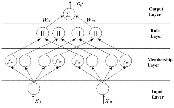
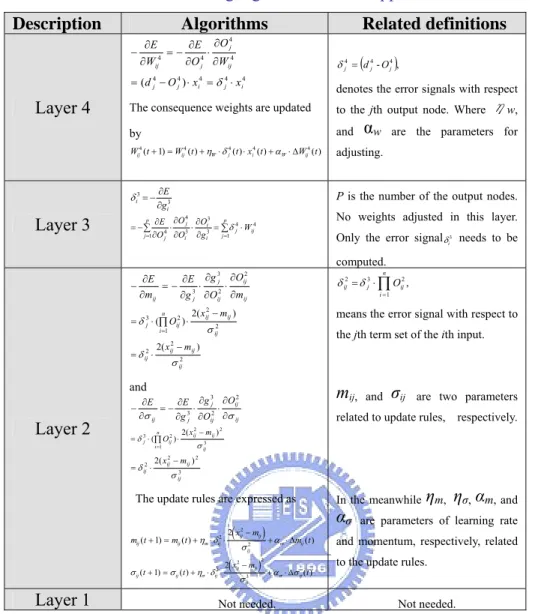
2.3.1 Four-Layer Feedforward Fuzzy Neural Networks...28
2.3.2 Partial Derivative Computation Scheme...32
Chapter 3 Parameters Identification Approaches
...333.1 Inductance Estimation ...33
3.1.1 Off-Line Scheme...35
3.1.2 On-Line Scheme...42
3.2 Resistance Estimation...42
3.3 Mutual Inductance Estimation...44
3.4 Speed and Torque Estimations ...46
3.4.1 Artificial Neural Network-Based Scheme...46
3.4.2 Fuzzy Neural Networks-Based Scheme...53
Chapter 4 Efficiency Control for Switched
Reluctance Motor Drives
...544.1 Conventional Dealing Opinions ...56
4.2 Reluctance-Based Analysis Concept ...57
4.2.1 Scheme with Inductance Information...58
4.2.2 Scheme without Speed Sensor Information...60
4.3 Power Relation for Optimizing Efficiency Planning...61
4.3.1 Optimizing Concept...62
4.3.2 Electrical Signals Planning...65
4.4 Efficiency Regulation Capability ...67
4.5 Constant Efficiency Application...68
4.5.1 Applied Speed Range...70
4.5.2 Applied Torque Range...70
4.6 Efficiency Observer Application ...70
Chapter 5 Performance Enhancement Study
...725.1 Compensation Rule for Resistance Variation ...72
5.2 Compensation Rule for Mutual Inductance Effect...73
5.3 Verifications...75
Chapter 6 System Implementation
...856.1 Introduction to Schemes and Functions ...85
6.2 Hardware Description...86
6.2.1 Block Diagrams for Functionalities...87
6.2.2 Efficiency Computation...87
6.3 Computer-Based Processing Structure ...88
7.2 Experimental Results...94 7.3 Performance Comparison ...97
Chapter 8 Conclusions
...101 8.1 Outlined Achievements ...101 8.2 Future Works ...104Bibliography
...107Appendix A-Applied Switched Reluctance Motor
Information
... 111Appendix B-Mechanical Parameters
... 112Appendix C- Patent Information of Japan
... 113Appendix D- Main Pages of the Datasheets of
Applying Chips for Power Computation
...121Vita
...123List of Tables
Table 1-1: The comparison for some motor in drive systems. ...4
Table 1-2: Information of efficiency-topic paper. ... 11
Table 1-3: SRM-related markets’ volume in 2005. ... 11
Table 1-4: Some application examples in product types...12
Table 1-5: The statistic plots based on US issued patents (issued before 2003)13 Table 1-6:MAYTAG washing machine related patents...15
Table 2-1:Learning algorithms for the applied FNN...32
Table 2-2: The comparison results for two operation conditions. ...37
Table 4-1: Arrangement of some common concepts for speed sensorless conrtrol techniques of SRM drives...60
Table 4-2: The operational planning for efficiency regulation...68
Table 5-1: The performance comparison results. ...78
Table A-1: The parameters’ information of the two SRMs. ... 111
Table B-1: The mechanical parameters of the applied SRMs. ... 112
List of Figures
Figure 1-1: The overview of electric machine drives research focuses based on
SRM...1
Figure 1-2: Information of paper amount statistic from INSPEC(time from 1994-2001). ...8
Figure 1-3: Information of research topics from INSPEC(time from 1994-2001). ...8
Figure 1-4: Information of cross-field research from INSPEC (time from 1994-2001). ...8
Figure 1-5: Information of paper amount statistics from IEEE(time from 1994-2001). ...9
Figure 1-6: Information of research topics from IEEE(time from 1994-2001). .9 Figure 1-7: Information of cross-field research from IEEE(time from 1994-2001). ...10
Figure 1-8: Information of paper amount based on countries from IEEE(time from 1994-2001)...10
Figure 1-9: The product-type SRM drives with patent protection. ...15
Figure 1-10: The operation flowchart of this research. ...21
Figure 1-11: The illustration of the organization for this dissertation...22
Figure 2-1: Cross section of an 8/6 SRM. ...24
Figure 2-2: The torque-current-inductance relation. ...26
Figure 2-3: The work plots for the magnetizing of the operation: (a)Unsaturated magnetizing; (b) Saturated magnetizing...26
Figure 2-4: The conventional SRM drive scheme...27
Figure 2-5: The simple analysis scheme for the drives based on circuit functions:(a) Voltage-controlled scheme;(b) Current-controlled scheme. 27 Figure 2-6: The FNN-based training scheme. ...28
Figure 2-7: The operation flow of estimation...29
Figure 2-8: The applied four-layer schematic representation for the kth output. ...29
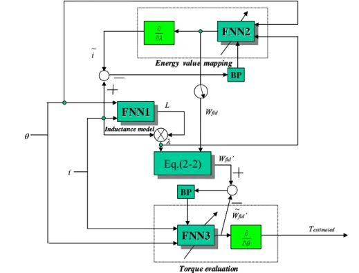
Figure 2-9: The overall schematic representation of the FNN analysis model for torque computation...35
Figure 2-10: The applicable scheme of the FNN analysis model for speed computation. ...35
Figure 2-11: The overall SRM drives scheme for verification...36
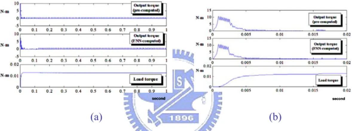
Figure 2-12: The torque estimation results of rated speed command:(a)Full-time period results ;(b)Transient results...37
Figure 2-13: The torque estimation results of 1/40 rated speed command:(a)Full-time period results;(b)Transient results...37
Figure 2-15: The speed estimation results of 1/40 rated speed command. ...38
Figure 3-1: Conventional inductance measurement methods for the SR motors: (a) The scheme that servo control motor is required for positioning; (b) The scheme that an angle measurement ruler and fix mechanism are needed for positioning. ...34
Figure 3-2: The relation for measurement...35
Figure 3-3.: The series type LC circuit related to the SRM. ...36
Figure 3-4: The parallel type LC circuit related to the SR motor...37
Figure 3-5: The linking relation of the proposed measurement method. ...41
Figure 3-6: The operation procedure for the inductance measurement...41
Figure 3-7: Resistance computation scheme-derivative type...44
Figure 3-8: Resistance computation scheme-Integral type. ...44
Figure 3-9: The operation flow for the dynamic model.. ...45
Figure 3-10: The ANN-based estimation scheme. ...48
Figure 3-11: The two-layer ANN for parameters estimation. ...49
Figure 3-12: The schematic representation for speed estimation...50
Figure 3-13: The schematic representation for torque estimation...52
Figure 3-14: The torque estimation computation procedure. ...53
Figure 3-15: The torque estimator scheme based on FNN...53
Figure 4-1: The loading types...56
Figure 4-2: The analysis scheme for SRM drives. ...57
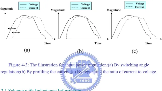
Figure 4-3: The illustration for input power regulation:(a) By switching angle regulation;(b) By profiling the current;(c) By regulating the ratio of current to voltage...58
Figure 4-4: The verification of the inductance mapping: (a) pre-measured inductance value; (b) the FNN learned inductance value; (c) the error between the two inductance value; (d) the overlaping plot...59
Figure 4-5: The difference plot of the torque computation:(a) under rated speed command; (b) under 1/40 rated speed command. ...60
Figure 4-6: Illustration for relation among powers. ...62
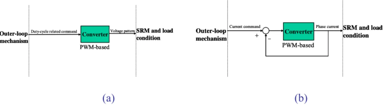
Figure 4-7: The operation scheme that without directly voltage-controlled capability...62
Figure 4-8: The operation scheme that with directly voltage-controlled capability...63
Figure 4-9: The illustration of optimizing concept...63
Figure 4-10: The function block for efficiency optimizing operation...64
Figure 4-11: Duty-cycle controlled scheme with adding of current control loop. ...65
Figure 4-12: Current hysteresis control scheme...65
current control. ...66
Figure 4-15: The comparison of estimated and pre-measured equivalent magnetic inductance that can be referred to efficiency capability...67
Figure 4-16: The operation schemes with performance judgment:(a)FNN-based scheme ;(b)ANN-based scheme;(c) Hybrid scheme. ...69
Figure 4-17: The information of applied speed range...70
Figure 4-18: The information applied torque range. ...70
Figure 4-19: The observer opinion to the proposed strategy...71
Figure 5-1: The current command compensation scheme based on change of resistance. ...73
Figure 5-2 : The overall schematic representation of the proposed model ...75
Figure 5-3: Resistance computation result. (1000 r/min, by derivative type) ...76
Figure 5-4: Resistance computation result. (1000 r/min, by integral type)...76
Figure 5-5: Operation record for compensation. ...76
Figure 5-6: The related results of speed command 925rpm without current compensation...77
Figure 5-7: The related results of speed command 925rpm with current compensation...77
Figure 5-8: The current compensation command...78
Figure 6-1: The modified base of SRM drives for verification...85
Figure 6-2:Photos of outward appearance and the taking apart states for the applied SRMs:(a) SRM 1;(b) SRM 2. ...86
Figure 6-3: The electric properties information acquiring scheme. ...87
Figure 6-4: The block diagram for functionality evaluation. ...87
Figure 6-5: The operation for efficiency computation scheme based on the logic relation...88
Figure 6-6: The experimental platform for torque/speed estimation...89
Figure 6-7: The set-up experimental scheme for efficiency index verification.89 Figure 6-8: The representative scheme of experimental setup for inductance measurement...90
Figure 6-9: The processing scheme for the computer-based system...90
Figure 7-1: The optimizing efficiency control scheme for the SRM drive. ...92
Figure 7-2: The developed driving circuit that is applied to SRM 1 related measurement and estimation. ...92
Figure 7-3: The developed driving circuit that is applied to SRM 2 related measurement and estimation. ...93
Figure 7-4: The measurement scheme for the optimizing efficiency operation. ...93
Figure 7-5: An example of the PC monitoring screen under operation...94
Figure 7-6: The comparison of the inductance profile at 6000r/min for the SRM 1. ...94
Figure 7-7: The comparison of the inductance differential value with respect to rotor angle of SRM 1 by the proposed estimation method and
post-computed method. ...95 Figure 7-8: The comparison of the inductance profile for the SRM 2 - 1 Ampere (under-saturation condition). ...96 Figure 7-9: The comparison of the inductance profile for the SRM 2 - 6 Ampere (saturation condition). ...96 Figure 7-10: The response record for the optimizing efficiency
operation(240r/min)...97 Figure 7-11: The comparison of the inductance values at aligned position for
SRM 1...98 Figure 7-12: The comparison of the inductance values at unaligned position for
SRM 1...98 Figure 7-13: The comparison of the inductance values at aligned position for
SRM 2...99 Figure 7-14: The comparison of the inductance values at unaligned position for
SRM 2...99 Figure 7-15: The efficiency comparison for SRM 1 (with ordinate of 100 times
transformation). ...100 Figure 7-16: The efficiency comparison for SRM 1 (with ordinate of 100 times
Nomenclature
Wr : motor speed
Vdc : DC bus voltage of the driving circuit
i: current V: voltage Te: outputted torque
Tl: loading torque
Bm: viscous coefficient
Jm: rotor moment of inertia
Eff: efficiency t : time
Suffix x: general phase representation Superscript
A,B,C,D a,b,c,d:
specific phase representation
Pin: input power
Pout: output power
L: equivalent magnetic inductance (inductance) M: mutual inductance
λ: flux linkage R: phase resistance
im1: the current flows through Lx
Vm: the supply voltage
t0: initial analysis time for series type circuit
ist0: the current value flows through Lx at t0
Cm1: the adding capacitor
Vm1: the voltage of Cm1 for series type circuit
Vst0: the voltage of Cm1 at t0
im2: the current flows to the branch leg with Lx
im: the supply current
t01: initial analysis time for parallel type circuit
ipt0: the current value flows through Lx at t01
Cm2: the adding capacitor for parallel type circuit
Vm2: the voltage of Cm2
Chapter 1 Introduction
Chapter 1 Introduction
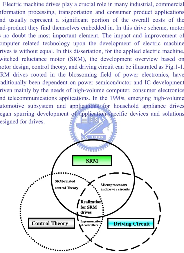
Electric machine drives play a crucial role in many industrial, commercial, information processing, transportation and consumer product applications and usually represent a significant portion of the overall costs of the end-product they find themselves embedded in. In this drive scheme, motor is no doubt the most important element. The impact and improvement of computer related technology upon the development of electric machine drives is without equal. In this dissertation, for the applied electric machine, switched reluctance motor (SRM), the development overview based on motor design, control theory, and driving circuit can be illustrated as Fig.1-1. SRM drives rooted in the blossoming field of power electronics, have traditionally been dependent on power semiconductor and IC development driven mainly by the needs of high-volume computer, consumer electronics and telecommunications applications. In the 1990s, emerging high-volume automotive subsystem and applications for household appliance drives began spurring development of application-specific devices and solutions designed for drives.
SRM
Control Theory Driving Circuit
SRM-related
control Theory Microprocessors and powe r circuits
Realization for SRM drives Imple mentati on of controllers SRM
Control Theory Driving Circuit
SRM-related
control Theory Microprocessors and powe r circuits
Realization for SRM drives
Imple mentati on of controllers
Figure 1-1: The overview of electric machine drives research focuses based on SRM.
Chapter 1 Introduction
decades. SRM is characterized by high power density, high robustness with temperature up to 600 centigrade degrees, simple structure for low materials and manufacturing cost, and wide speed range, is double- salience that having no winding in its rotor. Because of the above advantages, the research for putting it into more extensive industrial and daily-life applications attracts a lot of attention recently. Though SRM takes advantages on several aspects, performance and related estimation methods still need more related efforts involved to make SRM apply to high precision servo-level applications. However, SRM has drawbacks such as high non-linearity of coupling parameters relation, which is difficult to improve performance of controllers design, described in [31,67]. Obviously, the future research of SRM should not only focus on motor design, driving circuit development, and control strategies that applied, but also take the motor parameters estimation and identification into account, which all are the important requirements for various kinds of SRM drives. A comparative information of the popularly applied motors among DC brush motor, induction motor (IM), permanent magnet synchronous motor (PMSM), and SRM is arranged in Table 1-1. To date, induction motors have mainly been used for heating, ventilation and air conditioning (HVAC) applications, however, there is significant research being done worldwide for evaluation of such applications while an SRM is utilized. So far the overall cost involving the market-volume issue for SRM drives makes it uneconomical to expand their application to home appliances but it is the objective of this dissertation achieved by presenting an optimizing efficiency strategy to make the SRM own more advantages while considering it as applicable usage conforming to the strictly regulated energy saving with acceptable performance. The needed driving circuit to the SRM is similar to a brushless DC motor (BLDC) or AC vector variable frequency drive (VFD). Insulated gate bipolar transistor (IGBT) are typically used in an SRM drive’s inverter section. As such, SRM drives product design today is focused on producing cost-effective custom designs for different SRM designs under development for specific applications. Based on our experience within this research and discussion according to the visiting information from TECO Corp., SAMPO Technology Corp., and DELTA Electronics, Inc., the requirement to enhance the functionality of the SRM drives is one important gap to make them with more attention to consider the feasibility to putting them into present high-volume applications, no matter in household usage or industrial practice. The current trend in SRM drives’ development is to design the drive to meet the specific requirements such as efficiency improving, being a useful way to discuss the controller operation mechanism to the drive and may contribute a lot for some specific applications.
Chapter 1 Introduction
Besides, under some survey information during the evaluation phase of this research, a topic that can be clearly found is the need for energy conservation and higher efficiency is global. It affects both products and processes. It spans industrial, commercial and consumer applications. It may be driven both by government mandate and by the need for greater productivity in order to be competitive in increasingly-global markets according to industrial opinion. In addition, in our daily life, a product with better efficiency regulation capability is expected as well. So far, energy conservation and efficiency manifests itself in the drive market by increasing the demand for use of drives in fans, pumps and compressors used in building HVAC systems, industrial HVAC systems, water and wastewater pumping systems, building water delivery systems, chemical processing, utility equipment, material-handling equipment, household appliances, commercial refrigeration, etc.. A strategy that may result in a significant improvement in efficiency of the SRM drives is naturally becoming the driving force to proceed this research.
The design process for the topics discussed in the consideration of both traditional and advanced research and development related to design problems of products usually focused on the functionality. The needs (N), applying approaches(A), bringing benefits(B), and owning competitions(C), that is, so-called NABC analysis method, and the opinions can be concluded easily from the former description in needs, benefits, and competitions, hence, the approaches that construct the highly connected NABC chains should be devoted for researcher in this field. Based on author’s observation, an efficiency improvement strategy for SRM drives is needed and it motivates me to find a useful approach to achieve this goal. Moreover, the strategy can also drive development of more advanced control schemes to optimize performance for SRM drives is another expectation.
The important factor in electrical drives is high efficiency and low cost. The SRM has the rugged and simple structure in which no winding, no magnets and no brush on the rotor, thus, its manufacturing techniques is relative simple and the manufacturing cost is lower than the other machines, such as synchronous machine, DC machine, and induction machine. The SRM has had inherent advantages on those issues, but needs more feasible approach to promote its features for acceptance in applications. It can be observed that the number of SRM commercial product is still very small, and only few of these have volumes of more than 100,000 per year[54].
Chapter 1 Introduction Table 1-1: The comparison for some motor in drive systems.
Types Items DC brush motor IM PMSM SRM Volume × ※ ○ ◎ Cost of material ※ ○ × ◎ Cost of manufacturing ※ ○ ※ ◎ Reliability ○ ※ ※ ◎ Speed range ※ ○ ※ ◎ Power range ○ ◎ ※ ◎ Robustness ※ ○ ※ ◎ Efficiency ○ ※ ◎ ○ Torque ripple ○ ○ ○ × Noise ○ ○ ○ ※
Position information Without-applicable Without-applicable Needed Needed
Driving circuit Needed Without-applicable Needed Needed
Main application Servo Servo/Power Servo Power
◎:Excellent ○:Better ※:Good ×:Inferior
1.1 Motivations and Objectives
Switched reluctance motor, the electrical machine utilizes reluctance torque, is gaining acceptance in variable speed applications worldwide. In electrical machines related research, one of the most challenging tasks is the complexity of the implementing for the efficiency control, mentioned in[1,3,13,14,41,48,50,56,57,59]. Only few have considered the efficiency improvement among the SRM drives studies issued on that by a simple control strategy for ease of practical applications. For the efficiency research, most efforts have been devoted to the SRM structure design and it can be clearly realized from [19,48,49,53], which is focused on the modified type and special design for motor phase number, flux path, and air gap parameters to achieve the efficiency improvement. The circuit topologies for SRM drives are also taken to be the research topics for the efficiency research, such as dual-decay converter, C-dump inverter, and modified (n+1) switch converter, which have been described in [56,57], respectively. Besides of that, the current profile via switching angle control is also applied to involve the efficiency related research opinions [18]. To integrate the considerations
Chapter 1 Introduction
originate from a motor model research, a method that being proposed is the optimizing efficiency control which makes use of the parameter information based on the equivalent magnetic inductance, hereafter can be described as inductance, without losing the conventional performance requirement in a simple way. The optimizing efficiency control is a novel current command decision method for adding the efficiency regulation capability for the SRM drives[24,25,75,76]. In practice, the proposed optimizing efficiency strategy needs some information of parameters to form a control scheme with considerations of actual operation states. Thus, followings will also arrange the related research topics for parameters that may be needed or helpful to this efficiency improving approach. .
Inductance:
For improving the performance of SRM drives, several approaches had been proposed and focused on the inductance measurement related issues. The frequency of inducing signal would be useful to enhance the measurement precision, addressed in [6,12,33,34,36,37,60]. The position estimation using the information of inductance profile to excite the stator winding at appropriate instant is applied referred to [58,44]. Besides of that, the inductance information is also taken in SRM sensorless drives applying resonant method, linked control strategy design, and flux estimation, respectively, in [58,60,33,34].
Mutual inductance:
A method that provides dynamically analytical information reflecting accurate working properties of SRM is needed [4,10,11,24,26,27,29,54,55]. However, most analytical schemes are either based on the simplified model or sophisticated mathematical computations, which means elimination of some parameters that are not measurable during operation or complex analytical functions may be involved. Broadly speaking, the SRM adjacent phases have overlapping current conduction, and hence there exists mutual flux linkages between these adjacent phases that result in mutual inductance between the windings. Some researchers have been devoted to the related studies for the influence of the mutual inductance in SRM drives [30,54]. Thus, the practical SRM drives system applied in the applications, such as high-speed and high-performance drives, to contain identification scheme of all affection parameters, including the mutual inductance, has been the trend in drive technology as long as it allows an easy utilization relationship with
Chapter 1 Introduction
been utilized to try to achieve both the improvement of parameters estimation and drives performance [26,29,30,54,55].
Resistance:
In sensorless drive, the parameter of phase resistance, hereafter can be called resistance, plays a crucial role to the speed estimation [2,61]. The resistance of switched reluctance motor may change with temperature obviously, and it has been the goal to find the value under operation described in [61,65]. Especially in low-speed operation, the influence of the resistance may lead to a larger portion to the estimation of speed[31,65]. Generally speaking, direct measurement, one-point probe measurement, two-point probe measurement, linear four-point measurement, and nonlinear measurement can be applied in resistance measurement, however, it may not be accepted in practice for consideration of convenience of usage and cost related issues.
Speed:
Designs of Sensorless’ SRM drives have eliminated the encoder in systems. Most sensorless methods monitor the current and voltage in each winding of the motor in order to estimate the inductance from which position can be inferred by the use of look-up tables. In order to reduce cost and increase reliability and minimize sensitivity to line voltage and temperature variations, new sensorless techniques are under development, such as Mavrik Motors (U.S.) staggered tooth design motor system. Other techniques shape an induced voltage in an inactive phase of the motor adjacent to an energized phase in order to estimate the shaft position of the motor’s rotor. Related researches on the parameters identification and estimation for SRM have moved toward on-line estimation from off-line operation and computation described in [25,31]. Furthermore, there are more researches focusing on the combination of parameters estimation applied in sensorless drives discussed in [31,45].
Torque:
Many methods proposed for estimation of torque address fundamental issues about requirement of reflecting its accurate properties [38,41,52]. However, most analytical schemes are based on the simplified linear torque model and sophisticated mathematical computations may involve, or require large numerical tables for looking up [22,23,39,40,42]. Furthermore, the linear model contradicts the fact of high proportion magnetic saturation
Chapter 1 Introduction
operation for SRM, which means that the neglect of nonlinear effect probably yield poor computation results. Likewise, during on-line operation, the model structures and parameters of SRM may differ from the standstill ones due to the related effects of saturation and losses, especially at high current, which makes the previous schemes practically difficult to implement and thus can only be accurately described by a nonlinear model
[52,64,45]. Besides, some parameters of SRM are highly nonlinear functions
of phase current, rotor position, and rotor speed. They are not measurable during operation, and are hard to be expressed with analytical functions
[40,44]. Hence, a estimation model is needed herein to construct a torque
model to improve the torque evaluation capability. Moreover, it is also expected that being with the information acquired and computed from the torque estimation model, it can be applied for further speed estimation based on the motor electromagnetic derivation and it is applicable for speed sensorless applications.
1.2 Technology Trends from Literature
To observe more information for SRM drives, some databases are chosen to depict the trend of the related research, which include INSPEC (an indexing service for physics, engineering, computer science, and related fields. It also can be said as the database for Physics, Electronics, and Computing), Explore of IEEE (Institute of Electrical and Electronics Engineers), USPTO Patent Full-Text and Full-Page Image Databases, esp@cenet, and JP-Patnet Industrial Property Digital Library.
1.2.1 Academic Research Statistics
Figure 1-2 shows the published papers related to switched reluctance motor drives from 1994-2001 in INSPEC database. It keeps to attract the research effort to being involved. Fig. 1-3 illustrates the states of the research topics during this statistic period. It can be told that the research for actual application, which is the issue with minimum paper amount, is the key to narrow the gap to actual market [69]. A cross-field research statistics is made as well, shown in Fig.1-4, in which there are 66 papers may include at least two main topics on motor orientated design, control, overall drives, applications, and so forth.
Chapter 1 Introduction 0 10 20 30 40 50 60 70 80 Amount 1994 1995 1996 1997 1998 1999 2000 2001 Time 49 49 73 53 39 38 68 48 0 10 20 30 40 50 60 70 80 Amount 1994 1995 1996 1997 1998 1999 2000 2001 Time 49 49 73 53 39 38 68 48
Figure 1-2: Information of paper amount statistic from INSPEC(time from 1994-2001).
0 20 40 60 80 100 120 140 160 150 153 108 34 38 Amount Motor orientated
Control Drive Application Other
Classification 0 20 40 60 80 100 120 140 160 150 153 108 34 38 Amount Motor orientated
Control Drive Application Other
Classification
Figure 1-3: Information of research topics from INSPEC(time from 1994-2001).
0 20 40 60 80 100 120 140 160 Amount 1994-1995 1996-1997 1998-1999 2000 2001 Cross-field :(66) (15) (15) (15) (9) (12) Motor orientated Control Drive Application Other Time 0 20 40 60 80 100 120 140 160 Amount 1994-1995 1996-1997 1998-1999 2000 2001 Cross-field :(66) (15) (15) (15) (9) (12) Motor orientated Control Drive Application Other Time 0 20 40 60 80 100 120 140 160 Amount 1994-1995 1996-1997 1998-1999 2000 2001 Cross-field :(66) (15) (15) (15) (9) (12) Motor orientated Control Drive Application Other Time 0 20 40 60 80 100 120 140 160 Amount 1994-1995 1996-1997 1998-1999 2000 2001 Cross-field :(66) (15) (15) (15) (9) (12) Motor orientated Control Drive Application Other Time
Chapter 1 Introduction
By the similar analysis procedure, Fig.1-5 to Fig.1-7 illustrate the results of information from IEEE database. They obviously show the similar trends and development focuses. Fig.1-8 shows the amount order among the counties of the world. United States of America takes the leading role and Taiwan ranked in Top-10 in the time interval from 1994-2001. However, the drives of SRM exists a gap due to the relative less application with concerning issues in actual practice even the academic papers and published materials keeping growth, and most conferences related to electric drives include whole sessions on SRM .
0 10 20 30 40 50 60 70 80 90 Amount 19 94 19 95 19 96 19 97 19 98 19 99 20 00 20 01 Time 75 51 85 57 57 89 87 76 0 10 20 30 40 50 60 70 80 90 Amount 19 94 19 95 19 96 19 97 19 98 19 99 20 00 20 01 Time 75 51 85 57 57 89 87 76
Figure 1-5: Information of paper amount statistics from IEEE(time from 1994-2001).
Motor orientated
Control Drive Application Other
0 50 100 150 200 250 141 235 206 27 59 Amount Classification Motor orientated
Control Drive Application Other
0 50 100 150 200 250 141 235 206 27 59 Motor orientated
Control Drive Application Other
0 50 100 150 200 250 141 235 206 27 59 Amount Classification
Chapter 1 Introduction 0 20 40 60 80 100 120 140 160 180 1994-1995 1996-1997 1998-1999 2000 2001 :(91) (15) (24) (23) (11) (18) Motor orientated Control Drive Application Other Cross-field Amount Time 0 20 40 60 80 100 120 140 160 180 1994-1995 1996-1997 1998-1999 2000 2001 :(91) (15) (24) (23) (11) (18) Motor orientated Control Drive Application Other Cross-field Amount Time
Figure 1-7: Information of cross-field research from IEEE(time from 1994-2001).
0 20 40 60 80 100 Amount USA PRC Korea(N/S) UK Japan Indian Germany French Taiwan Italy Romania Poland Country Other 0 20 40 60 80 100 Amount USA PRC Korea(N/S) UK Japan Indian Germany French Taiwan Italy Romania Poland Country Other
Figure 1-8: Information of paper amount based on countries from IEEE(time from 1994-2001).
For narrowing the discrepancy between research and application, a novel strategy to the efficiency topic should be one solution to breakthrough the bottleneck. From the statistic results from 2002 to 2005 based on IEEE data, arranged in Table 1-2, an interesting opinion can be concluded as that the efficiency-related topic is a field attracting research effort with a ratio around 10% of the totally published papers in each year, however, it worth more research to be devoted in that for shortening the application gap and apparently forming a research group conforming to today’s energy requirement.
Chapter 1 Introduction Table 1-2: Information of efficiency-topic paper.
Time Paper amount Efficiency-related
paper amount Ratio(%)
2002 215 27 12.6
2003 214 16 7.5
2004 209 17 8.1
2005 112 12 10.7
1.2.2 Patent Information
By the information of related seminar from DELTA Electronics, Inc., which was partly presented referring the information of “A Global Market Research and Industry Outlook Report on Electronic Motor Drives 2001-2005” by Drives Research Corporation of Laguna Hills, California USA, Table 1-3 arranges the portion of the usages in specific product markets, which depict the mainly applying usages for the issued patents.
Table 1-3: SRM-related markets’ volume in 2005.
Applications Clothes washer drum Air conditioner fans Refrigerator fans
Portions AC VFD 33% UMD 18% SRD 17% BLDC 16% PMAC 16% BLDC 97% SRD 3% BLDC 90% SRD 10%
Note 1: SRD denotes SRM drives.
Note 2:PMAC is expressed for permanent magnet AC motor. Note 3: UMD is expressed for universal motor dirves.
The power semiconductor technology on which SRM drives are based can be considered mature. IGBTs were introduced in the late-1980s. By the mid-1990s, most AC and brushless drives manufacturers had learned how to use, apply and control IGBTs or MOSFETs and were using them in their low-voltage drives systems.
Table 1-4 arranges some remarkable applications of SRM drives in the world for applications close to power source usage.
Chapter 1 Introduction Table 1-4: Some application examples in product types.
Company/organization Product type/ function Features
Tridelta Industries Inc. Floor cleaning machine.
Electric bike.
Low start current. Multi-functions. Variable speed.
Emerson Electric Co. High-volume rolling cylinder-type washing machine. Higher efficiency. Without gear box.
Emerson Motor Co. Vacuum pumping.
Speed range more than 31000 r/min. Life cycle more than 10000 hours. High speed ratio.
Ford Automobile Co. Power steering. High power density.
Low cost. AMC, Densei and Westinghouse
Electronics Co. Traction car.
High power.
Airplane’s manufactures in UK Flight brake plate actuator. High power. High reliability.
Military of USA Generator. Jet’s petroleum pump. High reliability. Conforming to military standard.
More information related to those products, it can be found by the following companies or web addresses as:
Emerson Electric(USA), Emerson Motor(USA)( www.srdrives.com), Tridelta Industries, Westinghouse(USA), Allenwest(UK), Densei(Japan), AMC(www.amc-inc.com),
Motorsoft(www.motorsoftmotors.com), and so forth.
Example 1:
Switched Reluctance Motor Traction Drives
AccuSwitch-3000
VSR Servo Controller TracMotion-2000 VSR Traction Drive
HighPower
VSR Servo Motors TracMotion VSR Traction Motors
(Product information from AMC Web page) Example 2:
(Product information from Emerson web page)
High rate of filing patents exist especially in the United States, Europe, and Japan [67]. Followings will present some statistics information based on these regions. The statistic plots of US patents including life cycle of
Chapter 1 Introduction
technology, the leading countries in patent issued amount, international patent classification (IPC), and the leading patents based on cited number, are arranged in Table 1-5.
Table 1-5: The statistic plots based on US issued patents (issued before 2003) Main key
words Statistic plots using software of PatentGuider (Learning Tech. Co.)
Lift cycle of technology Leading cited patents SRM
IPC classification Leading countries
Lift cycle of technology Leading cited patents Washing
machines +SRM
IPC classification Leading countries
SRM +
torque
Chapter 1 Introduction
IPC classification Leading countries
Technology lift cycle Leading cited patents SRM + torque + noise
IPC classification Leading countries
Based on the patent information in the United States of America, it is clear that, the development of SRM and SRM drives is still laying in a growth phase for a long-term analysis for technologies. Besides, during the same ending time of 2003, patents issued by Japan related to keywords of SRM reach number of 321(the related items are collected in Appendix C), however, the strategy of motor design using interior permanent magnet (IPM) is the main stream. Meanwhile, there merely own 75 patents in Euro-patent database with the latest data collection date of May 2002 using the searching keyword of SRM. By the two statistic sources, system enhancement coming from control opinions still contribute less for SRM drives.
As the former mentioned high-volume rolling cylinder-type washing machine (brand: MAYTAG) using the SRM produced by Emerson Co.(specified as SRM 2 and the related information is given in Appendix A and Appendix B), the related introduction can be found in the web (http://www.srdrives.com/html/apps/emerson.htm) as shown in Fig.1-9.
Chapter 1 Introduction
Figure 1-9: The product-type SRM drives with patent protection.
To observe more development trend and information of the leading company, Emerson Electric Co, Table 1-6 arranges the related patents (issued by US ) for this product shown in Fig. 1-9.
Table 1-6:MAYTAG washing machine related patents
Number Date Title Abstract
5,467,025 November 14, 1995 Sensorless rotor position measurement in electric machines
A sensorless rotor position measurement system comprises a digital processor (6) which receives signals from current and flux sensors (7, 8) of the current and flux associated with a phase winding of the machine. The measurement of the current and flux is enabled at a predicted reference rotor position. The measurements are compared with stored values of current and flux and an error between the actual and the predicted reference position calculated. The calculated rotor position can then be used to predict the instant the rotor will reach the next reference position. 5,637,972 June 10, 1997 Rotor position encoder having features in decodable angular positions
A rotor position encoder for an electric motor includes a discate member mounted to rotate with the rotor shaft. The encoder has a set of radially extending features formed with angularly evenly spaced leading edges and unevenly spaced trailing edges. The leading edges induce a signal in a sensor that corresponds to the relative timing of power switches for each motor phase, The trailing edges define a cyclical code by which motor controlling circuitry is able to determine the phase of rotation of the rotor and thus establish the correct power switch actuation sequence. An electric motor control system and methods of starting electric motors also provide significant advantages.
Chapter 1 Introduction encoder having features in decodable angular positions
shaft. The encoder has a set of radially extending features formed with angularly evenly spaced leading edges and unevenly spaced trailing edges. The leading edges induce a signal in a sensor that corresponds to the relative timing of power switches for each motor phase. The trailing edges define a cyclical code by which motor controlling circuitry is able to determine the phase of rotation of the rotor and thus establish the correct power switch actuation sequence. An electric motor control system and methods of starting electric motors are also shown.
5,563,488 October 8, 1996 Control of switched reluctance machines
A control system for and method of controlling a switched reluctance generator to maintain stable control of the generator in the continuous current mode. This is achieved by sensing the load on the generator, the speed of the rotor and the position of the rotor with respect to each phase winding in order to derive switching command signals to maintain the volt-seconds applied to the winding in each phase period so as to inhibit progressive flux growth in the phase windings by actuation of the controller switches.
5,545,964 August 13, 1996 Control of switched reluctance machines
A control system for and method of controlling a switched reluctance generator to maintain stable control of the generator in the continuous current mode. This is achieved by sensing the load on the generator, the speed of the rotor and the position of the rotor with respect to each phase winding in order to derive switching command signals to maintain the volt-seconds applied to the winding in each phase period so as to inhibit progressive flux growth in the phase windings by actuation of the controller switches.
5,469,039 November 21, 1995 Control of switched reluctance machines
A control system for and method for controlling a switched reluctance generator to maintain stable control of the generator in the continuous current mode. This is achieved by sensing the load on the generator, the speed of the rotor and the position of the rotor with respect to each phase winding in order to derive switching command signals to maintain the volt-seconds applied to the winding in each phase period so as to inhibit progressive flux growth in the phase windings by actuation of the controller switches. 5,446,359 August 29, 1995 Current decay control in switched reluctance motor
A control circuit (10) for controlling the residual or tail current decay in a single phase or polyphase SRM winding when a phase is switched from active to inactive. A Hall-effect type sensor (30) senses rotor position of the SRM. Current flows through a winding (W) of the motor when the motor phase winding is active; and, current flow into the winding decays to zero when the phase becomes inactive. Semiconductor switches (22) direct current flow into the winding when the phase is active and then redirect residual energy in the winding between an energy recovery circuit and an energy dissipation circuit when the phase becomes inactive. A PWM signal generator (44) provides PWM operating signals to the switches to control current flow first into the winding and then between the recovery and dissipation circuits. A control module (42), or microprocessor (52) with a PWM output, is responsive to rotor position information for controlling operation of the PWM signal generator. The signal generator provides PWM signals having one set of signal characteristics when
Chapter 1 Introduction there is current flow to the winding and a different set of characteristics when there is not. This produces alternate intervals of zero voltage and forced commutation residual current decay while the phase is inactive. During the decay interval, both the PWM frequency and pulse duty cycle are variable to produce a current decay scheme which eliminates ringing and motor noise.
5,461,295 October 24, 1995 Noise reduction in a switched reluctance motor by current profile manipulation
Apparatus (10) for controlling the current profile (P2) in a single or polyphase SRM (M) during the active portion of a phase. Switches (S1, S2) are closed during an active portion of a phase to direct current flow into a winding (W). A Hall effect sensor (14) and other sensors are used to sense various operating parameters of the SRM. A PWM signal generator (16), or microprocessor (20) is responsive to the sensor inputs to provide PWM operating signals (G2) to at least one of the switches to control current flow to the winding. The operating signals modulate the switch(es) for switch operation to be controlled as a function of the signal characteristics of the operating signals. This allows the current supply to the winding to be in accordance with the current profile. According to the profile, current flow is initially rapidly increased from zero to a peak value (I.sub.p ') when the phase becomes active. The current is then allowed to decrease from this peak to a second and lesser value (I.sub.p) by the time the phase becomes inactive. Current decays from this second value to zero when the phase becomes inactive. The transition in the current profile which occurs when the phase switches from active to inactive is no longer an abrupt transition, but is rather a more moderate one. This smoother transition reduces the amount of ringing in the motor, which normally occurs when current flow into the winding ceases, thereby to reduce motor noise.
5,786,646 July 28, 1998 Method and apparatus for aligning a rotor position transducer
An improved method and apparatus for aligning and mounting a rotor position transducer element to the shaft of an electric motor. One embodiment of the invention is is an apparatus and method for aligning and mounting a RPT element in the form of a shutter assembly. Specifically, the shutter contains a perforated extended portion that surrounds the opening for the shaft. An annular clamp ring, made of metal or other suitable material slip fits over the protruded portion of the shutter. The clamp ring can also further comprise so-called "ears" or other non-annular portions that cause it not to be circular in cross-section. The clamp ring allows the shutter to be securely fastened to the shaft of the rotor without causing torsional force which could cause misalignment of the shutter with respect to the optical sensor, or misalignment of the rotor to the stator assembly, or both.
As shown in Table 1-6, control strategy plays a portion to the protection of the product development, but the concept to improve the efficiency still is lacked.
Chapter 1 Introduction
1.3 Contributions of the Dissertation
The main contributions of this dissertation are addressed by outlined items as follows:
1)The scheme of optimizing efficiency control which applies the parameter’s linking relation is proposed.
2)The operation of efficiency regulation is realized by programming the ratio of phase current command to voltage within the inductance information under operation.
3)The FNN estimation scheme for parameters is constructed and integrated into the optimizing efficiency control scheme.
4)The mentioned parameters estimation schemes that can/may be integrated/combined into the proposed SRM drives are discussed as well as the analysis of the applicability of efficiency observer in future research.
5)The survey information of academic papers and issued patents of SRM and SRM drives are both presented in some statistics forms.
6)New approaches based on an artificial neural network (ANN) computation scheme related to parameters such as inductance, resistance, and outputted speed and torque are presented with capability of application of SRM sensorless drives and has been applied to providing the performance judgment information to the optimizing efficiency mechanism.
7)Two concepts of current command compensators operating under variations of resistance and existence of mutual inductance, which can enhance the capability of SRM drives including the proposed optimizing efficiency strategy, are presented.
8)Simulation models have been constructed for the SRM drives development.
Chapter 1 Introduction
9)Information and discussion on applicable drive schemes are arranged for reference of future research and emerging applications.
10)A verification system applying two SRMs is organized and realized by the platforms intended to demonstrate the SRM drives system in a efficient way.
Increased emphasis on energy conservation is leading researchers to look for better approaches to use energy efficiently. Usually, the drive for the need of more efficient power devices, results in the expense of higher cost, and complicating the cost-performance trade-off issues. The proposed optimizing efficiency strategy can deal with it within appropriate cost in hardware but with portable software concept that may be realized in a embedded system or module-like IC.
1.4 Organization of the Dissertation
The work presented in this dissertation has peoceeded according to the research procedure expreesed in Fig.1-10 and organized in eight chapters. These eight chapters are structured as follows:
Chapter 1 is entitled “ Introduction”. The details follow as the topics of 1.1 Motivations and Objectives, 1.2 Technology Trends from Literature, 1.2.1 Academic Statistics, 1.2.2 Patent Information, 1.3 Contributions of the Dissertation, and 1.4 Organization of the Dissertation, which arrranges the information for the states related to this research.
Chapter 2 is entitled ” Preliminary Concept and Applying Strategy”. It follows the sections of 2.1 Modeling of Switched Reluctance Motors, 2.2 Primary Classification for Switched Reluctance Motor Drives, 2.3 Utilizing Computation Scheme Based on Fuzzy Neural Networks, 2.3.1 Four-Layer Feedforward Fuzzy Neural Networks, 2.3.2 Partial Derivative Computation Scheme, and 2.4 Simulations and Analysis, which prensent the preliminary backgound for this research.
Chapter 1 Introduction
parameters’ estimaiton or measurement approaches are derived and discussed in this chapter. It follows the sections of 3.1 Inductance Estimation, 3.1.1 Off-Line Scheme, 3.1.2 On-Line Scheme, 3.2 Resistance Estimation, 3.3 Mutual Inductance Estimation, 3.4 Speed and Torque Estimations, 3.4.1 Artificial Neural Network-Based Scheme, 3.4.1.1 Speed, 3.4.1.2 Torque, and 3.4.2 Fuzzy Neural Networks-Based Scheme.
Chapter 4 is entitled ” Efficiency Control for Switched Reluctance Motor Drives” . The efficiency improvement mechanism and concept is introduced in this chapter. The operation and concpet of the optimizing concpet is disscussed in this chapter as well. The sections comes as 4.1 Traditional Dealing Opinions, 4.2 Reluctance-Based Analysis Concept, 4.2.1 Scheme with Inductance Information, 4.2.2 Scheme without Speed Information, 4.3 Power Relation for Optimizing Efficiency Planning, 4.3.1 Optimizing Concept, 4.3.2 Electrical Signals Planning, 4.4 Efficiency Regulation Capability, 4.5 Constant Efficiency Application, 4.5.1 Applied Speed Range, 4.5.2 Applied Torque Range, and 4.6 Efficiency Observer Application.
Chapter 5 is entitled ” Performance Enhancement Study” . Two current command compensation schemes are described in this chapter. The details followed by 5.1 Compensation Rule for Resistance Variation, 5.2 Compensation Rule for Mutual Inductance Effect, and 5.3 Verifications.
Chapter 6 is entitled ” System Implementation” . It follows the sections of 6.1 Introduction to Schemes and Functions, 6.2 Hardware Description, 6.2.1 Block Diagrams for Functionalities, 6.2.2 Efficiency Computation, and 6.3 Computer-Based Processing Structure. The system functionalities of circuits and the connections for schemes are described and illustrated.
Chapter 7 is entitled” Experimental Test and Analysis.” It describes the sections of 7.1 Experimental Setup, 7.2 Experimental Results, and 7.3 Performance Comparison. Several experimental results are given in this chapter to validate the performance and feasibility of the proposed optimizing efficiency control strategy.
Chapter 1 Introduction
Chapter 8 is entitled ”Conclusions”. All achievements are summarized and the research conclusions are drawn herein. Some achievements are re-described in this chapter and it includes the sections of 8.1 Outlined Achievements and 8.2 Future Works.
Motivations Industrial requireme nts Literature infor mati on Problem formulation Objective definition Applying system
Experimental setup and verification strategy Feasibility Realization Result collection Conforming to target no no yes Finished part of research yes Motivations Industrial requireme nts Literature infor mati on Problem formulation Objective definition Applying system
Experimental setup and verification strategy Feasibility Realization Result collection Conforming to target no no yes Finished part of research yes
Figure 1-10: The operation flowchart of this research.
A systematic illustration for the dissertation, shown in Fig.1-11, that may help in further understanding for the purpose of organization of the research.
Chapter 1 Introduction
Chapter 1 for SRM drives development understanding and to take as reference
Chapter 2 for introducing preliminary concept to SRM and SRM drives with mainly
applied estimation scheme Chapter 3 for applicable schemes related to
parameter estimation and measurement Chapter 8 for conclusion of the future development
of technology in this field of study
Chapter 4 for describing opinions of efficiency improvement to SRM drives Chapter 5 for ideas proposing of performance
enhancement strategy to SRM drives Chapter 6 and Chapter 7 both for introduction
and illustration of the set-up for verification
Applicable range P ro ced u re
Chapter 2 Preliminary Concept and Applying Strategy
Chapter 2 Preliminary Concept and
Applying Strategy
System modeling is a fundamental problem in system theory and many engineering problems as well as the important research topic in design and analysis of development tasks. A model with competence of obtaining the behaviour of the controlled plant is requested to support and enhance the control developments. In recent years, computational-intelligence techniques such as artificial neural networks, fuzzy logic, genetic algorithms, combined neuro-fuzzy approaches, and other nonlinear and biologically inspired techniques have become valuable tools to describe and help to upgrade variable control related indexes under plants with variable parameters effect, described in [5,25,42,41,52]. Fuzzy neural network (FNN), owning the adaptive mapping and fault-tolerant features, is usually a good choice for tackling the modeling problem. Because of highly nonlinear characteristics of the SRM, all the control schemes can not be avoided to deal with the control force related to these parameters, as classified in 1.1, even not fully considerable[7,8,15,17,21,22,23,40,63]. Normally, it may be realized by using a look-up table, i.e., the look-up table uses stored magnetic characteristics to provide the reference value, but it takes relative large space requirement to memory in processing unit. In addition, the fault tolerant capability is in lacked to such arrangement. As description above, FNN is taken to construct the mapping among inductance-related information, such as current, position, and torque, and introduced the applied scheme in this section as well.
2.1 Modeling of Switched Reluctance Motors
The machine shown in cross section in Fig.2-1 has eight stator poles and six rotor poles and is denoted as an 8/6 SRM. Each stator pole is surrounded by a coil, and the coils of two opposite stator pole are connected in series to form each of the four phase windings. The four phase windings are connected in sequence to a power converter that may be normally trigger either by a set of signals from shaft position sensor or various estimation-based strategies actuation method.
Chapter 2 Preliminary Concept and Applying Strategy
Figure 2-1: Cross section of an 8/6 SRM.
The direction of rotation can be driven to be either clockwise or counterclockwise by controlling the sequence of the current injecting to phase windings. To achieve high torque and power from a given frame size, most SR motors are operated so that the poles are significantly saturated when aligned and energized.
The reluctance of SRM changes with rotor position and phase current, which apparently affects the SRM’s output. The phase voltage equation of SRM can be expressed in the form of
dt d R i V x x x λ + ⋅ = (2-1)
where suffix x means phase a, b, and c, or successive letters; V,i, R, and λ
respectively denote phase voltage, phase current, resistance, flux linkage (product of phase current i and inductance L).
To find an expression for the motor torque production, the energy relation is firstly written as the field energy, which can be arranged as Eq.(2-2):
) , ( ) , ( ' θ λ λ θ fld fld i i W W = ⋅ − (2-2)
where θ, Wfld, W'fld, are the rotor position, field energy, and co-energy, respectively. The field energy and co-energy are nonlinear functions as pairs of parameters (current i, and rotor position θ) and (flux linkage λ, and rotor position θ).
![Fig. 3-10 shows the parameters relation when constructing the proposed ANN scheme [26,30], representing the main concept of this section](https://thumb-ap.123doks.com/thumbv2/9libinfo/8234657.171093/68.892.237.629.435.710/parameters-relation-constructing-proposed-scheme-representing-concept-section.webp)