國 立 交 通 大 學
應用數學系
碩 士 論 文
廣義的 Shuffle-Exchange 網路之
最佳全體對全體私人化交換
Optimal All-to-All Personalized
Exchange in General
Shuffle-Exchange Networks
研 究 生:陳柏澍
指導教授:陳秋媛 教授
中 華 民 國 九 十 六 年 六 月
廣義的 Shuffle-Exchange 網路之
最佳全體對全體私人化交換
Optimal All-to-All Personalized Exchange
in General Shuffle-Exchange Networks
研 究 生:陳柏澍 Student:Richard B. Chen
指導教授:陳秋媛 Advisor:Chiuyuan Chen
國 立 交 通 大 學
應 用 數 學 系
碩 士 論 文
A Thesis
Submitted to Department of Applied Mathematics
College of Science
National Chiao Tung University
in Partial Fulfillment of the Requirements
for the Degree of
Master
in
Applied Mathematics
June 2007
Hsinchu, Taiwan, Republic of China
廣義的 Shuffle-Exchange 網路之
最佳全體對全體私人化交換
研究生:陳柏澍
指導老師:陳秋媛 教授
國 立 交 通 大 學
應 用 數 學 系
摘 要
全體對全體私人化交換溝通(all-to-all personalized exchange communication)出現在 許多平行與分散式處理系統之應用。在文獻[12]中,Yang 以及 Wang 運用拉丁方 陣的技巧,針對了具有 unique-path 以及 self-routable 性質的多級式連接網路,提出 了時間複雜度為O(N)的最佳全體對全體私人化交換演算法。所有在文獻[12]中被 討論到的網路(包括 shuffle-exchange 網路),皆滿足 1 2n N = + (N 表示多級式網路的 輸入及輸出端的個數,n+1是多級式網路的階級數)。值得注意的是,Yang 以及 Wang 的演算法要求多級式網路中的每一階級裡的所有交換器的狀態都必須相同;換句話 說,Yang 以及 Wang 的演算法使用階級控制技術。在文獻[7]中,Padmanabham 提 出 了 廣 義 的 shuffle-exchange 網 路 ; 在 廣 義 的 shuffle-exchange 網 路 中 , 1 2 2n <N ≤ n+ ,不再要求 1 2n N = + 。由於廣義的 shuffle-exchange 網路不一定具有 unique-path 性質,因此無法使用 Yang 以及 Wang 的演算法。本論文的目的即在於: 針對廣義的 shuffle-exchange 網路,提出兩個最佳全體對全體私人化交換演算法。和 Yang 以及 Wang 的演算法不同的是,我們的演算法沒有使用拉丁方陣,也不要求網 路要具有 unique-path 性質。我們的第一個演算法使用階級控制技術,而且適用於任 何的N;我們證明了:當要求使用階級控制技術、而且 1 1 2 2 2n− + n ≤N ≤ n+ 時,此演 算法是最佳的。我們的第二個演算法不使用階級控制技術、而且只適用於N =2n+2 時;我們證明了,此演算法是最佳的。 關鍵詞:多級式網路,平行與交換式計算,全體對全體溝通,全體對全體私人化交 換。
中 華 民 國 九 十 六 年 六 月
Optimal All-to-All Personalized Exchange
in General Shuffle-Exchange Networks
Student: Richard B. Chen
Advisor: Chiuyuan Chen
Department of Applied Mathematics National Chiao Tung University
Abstract
All-to-all personalized exchange communication has been widely applied in many parallel and distributed processing applications. In [14], by the Latin square method, Yang and Wang proposed an optimal all-to-all personalized exchange algorithm for the unique-path, self-routable multistage interconnection networks (MINs). All the networks considered in [14], including the famous shuffle-exchange networks, satisfy
N = 2n+1, in which N is the number of inputs (outputs) and n + 1 is the number
of stages of the network. Do notice that Yang and Wang’s algorithm requires the states of all the switches of a stage to be identical; i.e., the stage control technique is used. In [9], Padmanabham proposed the general shuffle-exchange network (GSEN) with 2n < N ≤ 2n+1. Since a GSEN is not necessarily a unique-path MIN, Yang
and Wang’s algorithm may not apply. The purpose of this paper is to propose two optimal all-to-all personalized exchange algorithms for GSENs. Unlike Yang and Wang’s algorithm, we abandon the Latin square method and the requirement on the unique-path property. The first algorithm uses the stage control technique and works for arbitrary N . We will prove it is optimal when the stage control technique is assumed for 2n−1+ 2n≤ N ≤ 2n+1. On the contrary, the second algorithm does
not use the stage control technique and works only for N = 2n+ 2. We will prove
that it is optimal.
Keywords: multistage interconnection network, parallel and distributed com-puting, all-to-all communication, all-to-all personalized exchange.
誌 謝
光陰似箭,歲月如梭,轉眼間兩年已經過去了。還記得當初考上國
立交通大學應用數學系,是組合界擁有堅強師資陣容的系所。懷著期待
的心情進入。
組合組擁有優秀師資,以及團結和睦氣氛!在這種環境下,同學間
不僅生活上感情融洽,課業上也互相扶持。短短的時間內,老師們的教
導更開闊我的視野。感謝陳秋媛老師的演算法等課程、傅恆霖老師的圖
論課程、翁志文老師的組合編碼等課程,以及黃大原老師的設計理論等
課程。不只是理論的教導,更展延相關的應用。
其中最感謝的老師,莫過於我的指導老師:陳秋媛教授。她不只是
老師,更像是一位朋友。學業上,教了我許多知識;生活上,更像是患
難相助的好朋友。在待人處事方面,也開導我許多。
還有要感謝國立中央大學的單維彰老師。他曾是我大學導師,也教
過我許多科目。也因為老師的關係,讓我除了數學,在電腦知識、技能
方面也有好的表現。
最後感謝我同屆的同學:介友、宜廷、文強、澍仁、國安、張圳、
雁婷、妙玲,由於你們在生活及課業的互相幫忙,讓我在這兩年留下美
好回憶。還有同學:威雄、鈺傑、子鴻、志文以及博士班的學長:國元、
宏賓。有你們的參與下,讓我的生活多采多姿!
最後感謝我的父母,從小拉拔我、栽培我,持續鼓勵、支持我。你
們是我成功最大推手!感恩的心,不止於此,僅以微薄紙筆,代表我心!
Contents
Abstract (in Chinese) i
Abstract (in English) ii
Acknowledgement iii
Contents iv
List of Figures v
1 Introduction 1
2 Some preliminaries 4
3 All-to-all personalized exchange in GSENs with stage control 6 4 All-to-all personalized exchange in GSENs with N = 2n+ 2 10
List of Figures
1 Communications among processors using an MIN. . . 2
2 A 10 × 10 MIN which is also a 10 × 10 GSEN. . . . 2
3 The states of a 2 × 2 swtich. . . . 3
4 The network configuration of the GSEN in Figure 2. . . 5
5 An example of phase 1 of Algorithm GSEN-ATA-2. . . 20
1
Introduction
Processors in a parallel and distributed processing system often need to communicate with other processors. The communication among these processors could be one-to-one,
one-to-many, or all-to-all. In particular, all-to-all communication can be further classified
into all-to-all broadcast and all-to-all personalized exchange. In all-to-all broadcast, each processor sends the same message to all other processors; while in all-to-all personalized exchange, each processor sends a specific message to every other processor. This paper focuses on all-to-all personalized exchange.
All-to-all personalized exchange occurs in many important applications (for exam-ple, matrix transposition and fast Fourier transform (FFT)) in parallel and distributed computing. Since a processor can send only one message in each time unit, the time to complete all-to-all personalized exchange is Ω(N), where N is the number of processors in the given network. The all-to-all personalized exchange problem has been extensively studied for hypercubes, meshes, and tori; see [8, 14] for details. As was mentioned in [14], although the algorithm for a hypercube achieves optimal time complexity, a hypercube suffers from unbounded node degrees and therefore has poor scalability. On the other hand, although a mesh or torus has a constant node degree and better scalability, its algorithm has a higher time complexity [14]. An MIN (defined later) is considered to be a better choice for implementing all-to-all personalized exchange due to its shorter communication delay and better scalability.
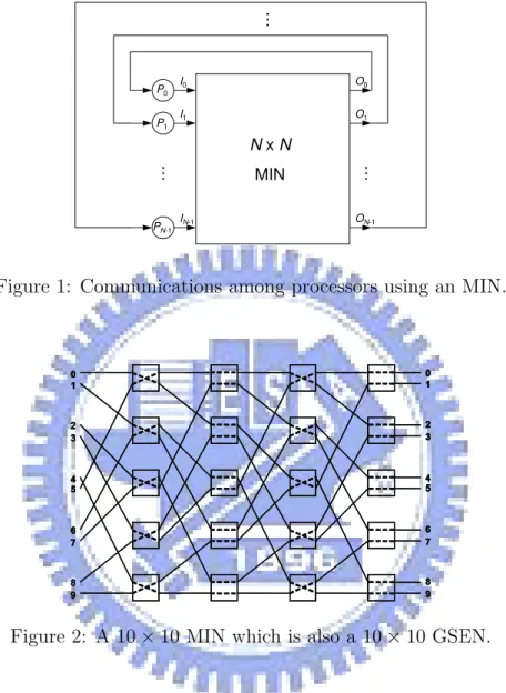
Given N processors P0, P1, · · · , PN −1, an N × N multistage interconnection network
(MIN) can be used for communication among these processors as shown in Figure 1, where
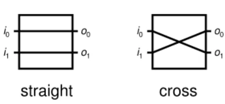
N × N means N inputs and N outputs. Figure 2 shows an example of a 10 × 10 MIN.
A column in an MIN is called a stage and the nodes in an MIN are called switches (or
switching elements or crossbars). Throughout this paper, an MIN means an N × N MINs
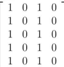
[1, 2, 3, 5, 7] for switches of other sizes. It is well known that a 2 × 2 switch has only two possible states: straight or cross, as shown in Figure 3.
N x N MIN P0 P1 PN-1 I0 I1 IN-1 O0 O1 ON-1 … … …
Figure 1: Communications among processors using an MIN.
0 1 2 3 4 5 6 7 8 9 0 1 2 3 4 5 6 7 8 9 0 1 2 3 4 5 6 7 8 9 0 1 2 3 4 5 6 7 8 9 0 1 2 3 4 5 6 7 8 9 0 1 2 3 4 5 6 7 8 9 0 1 2 3 4 5 6 7 8 9 0 1 2 3 4 5 6 7 8 9 0 1 2 3 4 5 6 7 8 9 0 1 2 3 4 5 6 7 8 9
Figure 2: A 10 × 10 MIN which is also a 10 × 10 GSEN.
Obviously, it is meaningless to consider a network that does not have a path between an arbitrary pair of input and output. An MIN is unique-path if there is a unique path between each pair of input and output. An MIN is self-routable if the routing decision at a switch depends only on the addresses of the source and the destination. In [14], Yang and Wang proposed an optimal all-to-all personalized exchange algorithm for a class of unique-path, self-routable MINs.
Yang and Wang’s algorithm [14] uses stage control (see [10]), which is a commonly used technique to reduce the cost of the network setting for all-to-all personalized exchange
cross straight i0 i1 i0 i1 o0 o1 o0 o1
Figure 3: The states of a 2 × 2 swtich.
communication. Stage control means that the states of all the switches of a stage have to be identical. With stage control, a single control bit (0 for straight and 1 for cross), or in other words, one electronic driver circuit, can be used to control all the switches of a stage. Thus the number of expensive electronic driver circuits needed is significantly lower than that of individual switch control.
Throughout this paper, N denotes the number of processors in a given MIN and
n + 1 is the number of stages in a given MIN. Since each switch is of size 2 × 2, N is an
even integer. All the networks considered in [14], including the famous shuffle-exchange networks, satisfy N = 2n+1. Shuffle-exchange networks have been proposed as a popular
architecture for MINs; see [4, 5, 6, 9, 11]. In [9], Padmanabhan proposed the general
shuffle-exchange network (GSEN) with 2n < N ≤ 2n+1. The N terminals in an N × N
GSEN are numbered 0, 1, · · · , N − 1 and the shuffle-exchange operation on N terminals is the permutation π defined by
π(i) = (2i + ¹ 2i N º ) mod N, 0 ≤ i ≤ N − 1.
See Figure 2 for an example. In the remaining part of this paper, we will simply use a GSEN to denote an N × N GSEN. Notice that in a shuffle-exchange network, N = 2n+1,
while in a GSEN, 2n< N ≤ 2n+1.
Although Yang and Wang’s algorithm [14] is optimal, it works only for unique-path MINs. Since a GSEN is not necessarily a unique-path MIN, Yang and Wang’s algorithm may not apply. Besides, Yang and Wang’s algorithm requires constructing a Latin square
in advance and allocating memory for storing the Latin square. In [14], the time for constructing the Latin square is not counted in the optimal O(N) communication delay. The purpose of this paper is to propose two optimal all-to-all personalized exchange algorithms for GSENs. Unlike Yang and Wang’s algorithm, we abandon the Latin square method and the requirement on the unique-path property. The first algorithm uses the stage control technique and works for arbitrary N. We will prove it is optimal when the stage control technique is assumed for 2n−1+ 2n≤ N ≤ 2n+1. On the contrary, the second
algorithm does not use the stage control technique and works only for N = 2n+ 2. We
will prove that it is optimal.
This paper is organized as follows: Section 2 gives some preliminaries. Section 3 is our first all-to-all personalized exchange algorithm. Section 4 is our second all-to-all personalized exchange algorithm. Concluding remarks are given in the final section.
2
Some preliminaries
In a GSEN, the switches are aligned in n + 1 stages: stage 0, stage 1, · · · , stage n. Each stage ` consists of N/2 switches denoted as s`
0, s`1, · · · , s`N/2−1 and s`(i+1) mod N is
considered to be the successive switch of s` i.
The network configuration of an MIN is defined by the states of its switches. Since a GSEN has N
2 × (n + 1) switches, the network configuration of a GSEN can be represented
by an N
2 × (n + 1) matrix in which each entry is defined by the state of its corresponding
switch. And, when the stage control technique is used, the network configuration of a GSEN can be represented by a number between 0 and 2n+1− 1. For example, the network
configuration of the GSEN in Figure 2 can be represented by the matrix in Figure 4 or by the number 10, which is (1010)2.
A permutation of an MIN is one-to-one mapping between the inputs and outputs. For an MIN, if there is a permutation that maps input i to output p(i), where p(i) ∈
1 0 1 0 1 0 1 0 1 0 1 0 1 0 1 0 1 0 1 0
Figure 4: The network configuration of the GSEN in Figure 2.
{0, 1, · · · , N − 1} for i = 0, 1, · · · , N − 1, then we will use
µ 0 1 · · · N − 1 p(0) p(1) · · · p(N − 1) ¶ or simply use p(0) p(1) · · · p(N − 1)
to denote the the permutation. Given a network configuration of an MIN, a permutation can be obtained. For example, the network configuration shown in Figure 2 maps input 0 to output 1, input 1 to output 4, input 2 to output 6, · · · , and input 9 to output 8; this configuration obtains the permutation
1 4 6 0 7 2 9 3 5 8.
Permutations realizable by an MIN are called admissible permutations. Not all of the
N ! permutations are realizable by an MIN. For example, the identity permutation is not
realizable by the MIN in Figure 2.
An N ×N Latin square is an N ×N matrix A = (ai,j) , i, j = 0, 1, · · · , N −1, such that
entries ai,j are in the set {0, 1, · · · , N − 1} and no two entries in a row or a column are
identical. In [14], Yang and Wang found that: to realize all-to-all personalized exchange for a unique-path, self-routable MIN, one only needs to arrange N network configurations so that their corresponding admissible permutations form an N ×N Latin square. By using this Latin square method, Yang and Wang [14] proposed an optimal all-to-all personalized exchange algorithm for a class of unique-path, self-routable MINs; see also [7, 8, 12, 13, 15].
In this paper, ⊕ denotes the XOR operation. As a reference, 0 ⊕ 0 = 0, 0 ⊕ 1 = 1, 1 ⊕ 0 = 1, 1 ⊕ 1 = 0.
3
All-to-all personalized exchange in GSENs with
stage control
In a GSEN, the messages are transmitted in a pipelining pattern. In the following, a
round means a process to transmit all the messages of the current stage to the next stage.
Before proposing our first all-to-all personalized exchange algorithm for GSENs, we will prove that when 2n+ 2n−1 ≤ N ≤ 2n+1 and the stage control technique is used, at least
2n+1+ n rounds are required to complete all-to-all personalized exchange in a GSEN. The
following lemma plays an important role in the remaining proofs.
Lemma 1. If the network configuration x maps input 0 to output j, then the network
configuration (x + 2n) mod 2n+1 maps input N/2 to the same output j. Moreover, x and
(x + 2n) mod 2n+1 differ only in the setting of stage 0.
Proof. Since the shuffle pattern makes input 0 and input N/2 link to the same switch of the stage 0, we have the lemma.
See Figure 2 for an illustration of this lemma. It is not difficult to see that the network configuration 10 maps input 0 to output 1 and the network configuration (10 + 8) mod 16, which equals 2, maps input 5 to the same output 1. Before going further, we introduce a definition. Output j is called a unique-path output of input i if the path between them is unique.
Lemma 2. If j is a unique-output of input 0, then j is also a unique-path output of input
Proof. Suppose to the contrary that the path between input N/2 and output j is not unique. Then by Lemma 1, the path between input 0 and output j will not be unique. Lemma 3. Input 0 has exactly 2N − 2n+1 unique-path outputs; these unique-path outputs
are consecutive and they are 2n+1− N, 2n+1− N + 1, · · · , N − 1.
Proof. Since the path between 0 and the switch sn
i is unique for 2n− N2 ≤ i ≤ N2 − 1,
we have this lemma.
The following lemma is obvious and its proof is omitted.
Lemma 4. Suppose j is a unique-path output of input 0. Then when the stage control
technique is used, the network configuration that maps 0 to j is exactly j.
Corollary 5. Suppose j is a unique-path output of input 0. Then when the stage control
technique is used, the network configuration that maps N/2 to j is exactly (j + 2n) mod
2n+1 .
Proof. This corollary follows directly from Lemma 1, Lemma 2, and Lemma 4.
We now derive a lower bound on the number of rounds required to complete all-to-all personalized exchange in a GSEN.
Theorem 6. When 2n + 2n−1 ≤ N ≤ 2n+1 and the stage control technique is used, at
least 2n+1+ n rounds are required to complete all-to-all personalized exchange in a GSEN.
Proof. By Lemma 3, U = {2n+1−N, 2n+1−N +1, · · · , N −1} is the set of unique-path
outputs of input 0. When 2n+2n−1 ≤ N ≤ 2n+1, we have S = {2n−1, 2n−1+1, · · · , 2n−1+
2n− 1} ⊆ U. Note that |S| = 2n. Let
and
S2 = {2n−1+ 2n, 2n−1+ 2n+ 1, · · · , 2n+1− 1, 0, 1, · · · , 2n−1− 1}.
By Lemma 4, the 2n network configurations in S
1 are required for input 0 to get to all the
outputs in S. By Corollary 5, the 2n network configurations in S
2 are required for input
N/2 to get to all the outputs in S. Since
S1∪ S2 = {0, 1, · · · , 2n+1− 1},
when the stage control technique is used, at least 2n+1network configurations are required
to complete all-to-all personalized exchange. Since at least 2n+1 network configurations
are required and it takes n + 1 rounds for a message to travel through a GSEN, we have this theorem.
We are now ready to propose our first all-to-all personalized exchange algorithm for GSENs. This algorithm uses the stage control technique and has two phases. The first phase is the message preparing phase and in this phase, personalized messages that need to be sent out from each processor are inserted into the message queue of that processor. The second phase is the message sending phase and in this phase, personalized messages are sent out from the message queue of each processor.
Algorithm GSEN-ATA-with-Stage-Control. Phase 1: The message preparing phase.
• The (n+1)-digit binary representations xnxn−1· · · x0 of numbers 0, 1, · · · , 2n+1−1
are sequentially generated and the labels of every input of the GSEN (the label of input 0 is 0, the label of input 1 is 1, etc) are equipped with the current binary representation xnxn−1· · · x0.
• Before a label enters switch sji, sji is set to straight if xn−j = 0 and set to cross if
• When a label reaches an output, a personalized message is prepared; in particular,
if label s reaches output t, then a personalized message that processor s wants to send to processor t is prepared and is inserted into the message queue of processor s.
Phase 2: The message sending phase.
• The (n+1)-digit binary representations xnxn−1· · · x0 of numbers 0, 1, · · · , 2n+1−1
are sequentially generated and the personalized messages in the message queue of every input of the GSEN are equipped with the current binary representation
xnxn−1· · · x0.
• Before a message enters switch sji, sji is set according to the rules used in phase 1.
• When a message reaches an output, that output receives a personalized message
for it.
End of the algorithm.
Theorem 7. Algorithm GSEN-ATA-with-Stage-Control is correct and takes 2(2n+1+ n)
rounds.
Proof. To prove the correctness of this algorithm, it is sufficient to prove that for an arbitrary pair of input i and output j, i can get to j. Since the stage control technique is used, there are only 2n+1 possible network configurations. The network configuration for i
to get to j is therefore a number in 0, 1, · · · , 2n+1− 1. Since Algorithm
GSEN-ATA-with-Stage-Control uses every number in 0, 1, · · · , 2n+1− 1 as one of its network configurations,
i can get to j. It is obvious that the above algorithm takes 2(2n+1+ n) rounds.
Corollary 8. When 2n + 2n−1 ≤ N ≤ 2n+1 and the stage control technique is used,
Proof. By Theorem 7, Algorithm GSEN-ATA-with-Stage-Control takes O(2n+1 + n)
rounds. By Theorem 6, when the stage control technique is used, the number of rounds required to complete all-to-all personalized exchange in a GSEN is Ω(2n+1+ n). We now
have this corollary.
4
All-to-all personalized exchange in GSENs with
N = 2
n+ 2
In this section, we will propose our second all-to-all personalized exchange algorithm for GSENs and we will assume that the given GSEN has exactly N = 2n+ 2 nodes. The
differences between our two algorithms are: The first algorithm uses the stage control technique and each phase of the algorithm requires 2n+1 + n rounds (notice that 2n <
N ≤ 2n+1). On the contrary, each phase of the second algorithm requires only N + n
rounds and only the first 2n(note that N = 2n+2) rounds use the stage control technique.
The following is the second algorithm; it also has two phases: the message preparing phase and the message sending phase.
Algorithm GSEN-ATA-2.
Phase 1: The message preparing phase.
• The (n + 1)-digit binary representations xnxn−1· · · x0 of numbers 0, 1, · · · , 2n− 1,
2n+ 2n−1, and 2n+ 2n−1+ 1 are sequentially generated and the labels of every
input of the GSEN (the label of input 0 is 0, the label of input 1 is 1, etc) are equipped with the current binary representation xnxn−1· · · x0.
• Before a label enters switch sji, sji is set according to the number x with which the label is equipped.
If x is neither 2n+ 2n−1 nor 2n+ 2n−1+ 1, then:
sji is set to straight if xn−j = 0 and set to cross if xn−j = 1.
If x is 2n+ 2n−1 or 2n+ 2n−1+ 1, then:
if j = 0 or j = n, then sji is set to straight if xn−j = 0 and set to cross if
xn−j = 1; otherwise, sji is set to straight if i ⊕ xn−j = 0 and set to cross if
i ⊕ xn−j = 1.
• When a label reaches an output, a personalized message is prepared; in particular,
if label s reaches output t, then a personalized message that processor s wants to send to processor t is prepared and is inserted into the message queue of processor s.
Phase 2: The message sending phase.
• The (n + 1)-digit binary representations xnxn−1· · · x0 of numbers 0, 1, · · · , 2n− 1,
2n+ 2n−1, and 2n+ 2n−1+ 1 are sequentially generated and the personalized
messages in the message queue of every input of the GSEN are equipped with the current binary representation xnxn−1· · · x0.
• Before a message enters switch sji, the switch is set according to the rules used in phase 1.
• When a message reaches an output, that output receives a personalized message
for it.
End of the algorithm.
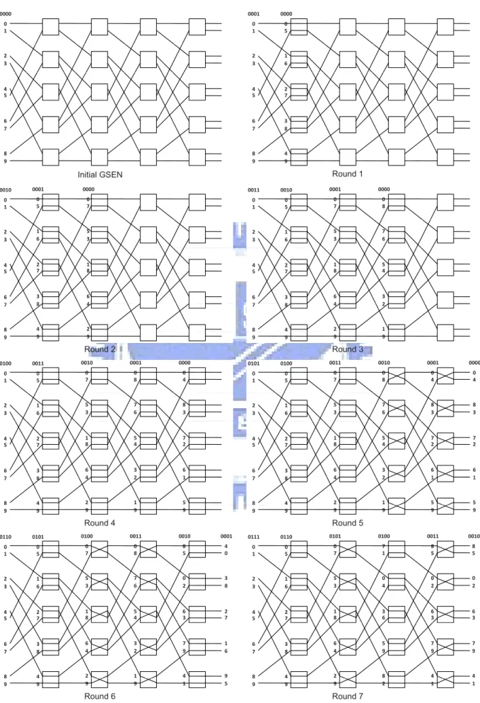
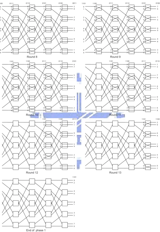
Phase 2 of Algorithm GSEN-ATA-2 is similar to phase 1 of Algorithm GSEN-ATA-2 except that a personalized message (instead of the label i) is sent from input i. So we only give an example for phase 1; see Figures 5 and 6. In these two figures, each 0-1 string is the binary representation of the number x with which a label is equipped. From these
two figures, the labels arriving at the outputs are as follows. for output 0 : 0 4 8 5 7 6 1 3 2 9 for output 1 : 4 0 5 8 6 7 3 1 9 2 for output 2 : 8 3 0 2 1 5 7 9 6 4 for output 3 : 3 8 2 0 5 1 9 7 4 6 for output 4 : 7 2 6 3 0 9 4 5 1 8 for output 5 : 2 7 3 6 9 0 5 4 8 1 for output 6 : 6 1 7 9 4 8 0 2 5 3 for output 7 : 1 6 9 7 8 4 2 0 3 5 for output 8 : 5 9 4 1 3 2 6 8 0 7 for output 9 : 9 5 1 4 2 3 8 6 7 0
It is not difficult to see that Algorithm GSEN-ATA-2 completes all-to-all personalized exchange for a GSEN with N = 10 nodes.
In the remaining part of this section, we will prove that Algorithm GSEN-ATA-2 is correct and optimal. Recall that the switches of stage ` are s`
0, s`1, · · · , s`N/2−1 and s`0
is considered to be the successive switch of s`
N/2−1. The following two observations are
based on the assumption that the setting of every switch of stage 0 is straight:
Observation 1. At stage 1, only one switch is reachable from input i. At stage 2, exactly 2 switches are reachable from input i and these switches are consecutive. In general, at stage `, 0 ≤ ` ≤ n, exactly 2`−1 switches are reachable from input i and these
switches are consecutive. At stage n (i.e., the last stage), exactly 2n−1 switches are
reachable from input i and these switches are consecutive.
Since the switches of stage ` that are reachable from input i are consecutive, we only need to know the first one; suppose s`
C` is this switch. Then we have the following observation.
Observation 2. C` = ½ i mod N/2 if ` = 0 , 2`−1(2i + b2i Nc) mod N/2 if 1 ≤ ` ≤ n.
We now use the above two observations to prove a lemma.
Lemma 9. If i ≤ N/2−1, then for each phase of Algorithm GSEN-ATA-2, after
perform-ing the first N + n − 2 rounds, only one switch of stage n (the last stage) is not reachable from input i. Moreover, if this unique switch is sn
qi, then qi = (2
Proof. When the stage control technique is used and the setting of every switch of stage 0 is straight, there are only 2npossible network configurations: 0, 1, · · · , 2n− 1. For each
phase of Algorithm GSEN-ATA-2, its first 2n rounds use the stage control technique and
the switches are set according to the (n + 1)-digit binary representations xnxn−1· · · x0 of
the numbers 0, 1, · · · , 2n− 1. So by Observation 1, for each phase of Algorithm
GSEN-ATA-2, after performing the first 2n+ n = N + n − 2 rounds, the number of switches
of stage n that are reachable from input i is 2n−1. Since each stage consists of 2n−1+ 1
switches, only one switch of stage n is not reachable from i. By Observation 2, if this unique switch is sn
qi, then qi = (Cn+ 2
n−1) mod N/2, i.e., q
i = (2n−1− 2i) mod N/2.
The following corollary follows directly from Lemma 9.
Corollary 10. q0 = 2n−1 and qi = (qi−1− 2) mod N/2 for i = 1, 2, · · · , N/2 − 1.
The proof of the following lemma is similar to that of Lemma 9 and is omitted here. Lemma 11. If i ≥ N/2, then for each phase of Algorithm GSEN-ATA-2, after performing
the first N + n − 2 rounds, only one switch of stage n (the last stage) is not reachable from input i. Moreover, if this unique switch is sn
qi, then qi = (2
n−1− 2i − 1) mod N/2.
The following corollary follows directly from Lemma 11.
Corollary 12. qN/2 = 2n−1− 1 and qi = (qi−1− 2) mod N/2 for i = N/2 + 1, N/2 +
2, · · · , N − 1.
Let M1 (M2), an N2 × (n + 1) 0-1 matrix, be the network configuration defined as
follows. For each 0 ≤ ` ≤ n, column ` of M1(M2) contains the setting of switches of stage
` at round 2n+ ` + 1 (2n+ ` + 2). When we do not want to specify which one of M 1 and
M2 is used, we will simply use M to denote either M1 or M2. From Algorithm
of 2n+ 1 and 2n+ 2, respectively. Since 2n+ 1 = (1100 · · · 00)
2 and 2n+ 2 = (1100 · · · 01)2,
the first n columns of M1 and M2 are identical and
(i) each entry in column 0 of M is 1,
(ii) 1 and 0 appear alternatively in column 1 of M,
(iii) 0 and 1 appear alternatively in column 2, column 3, · · · , column n − 1 of M, (iv) each entry in column n of M1 (M2) is 0 (1).
See the following for an illustration.
M1 = 1 1 0 0 · · · 0 0 0 1 0 1 1 · · · 1 1 0 1 1 0 0 · · · 0 0 0 1 0 1 1 · · · 1 1 0 ... · · · 1 0 1 1 · · · 1 1 0 1 1 0 0 · · · 0 0 0 1 0 1 1 · · · 1 1 0 M2 = 1 1 0 0 · · · 0 0 1 1 0 1 1 · · · 1 1 1 1 1 0 0 · · · 0 0 1 1 0 1 1 · · · 1 1 1 ... · · · 1 0 1 1 · · · 1 1 1 1 1 0 0 · · · 0 0 1 1 0 1 1 · · · 1 1 1
For convenience, denote the two subports on the left-hand (right-hand) side of a 2 × 2 switch i0 and i1 (o0 and o1); see Figure 3. In a GSEN, the right-hand side of every stage
has exactly N ports: port 0, port 1, · · · , port N − 1. For convenience, let p`
i denote the
label of the port on the right-hand side of stage ` that is reachable from input i. When the network configuration M is used, the following two properties hold.
Property A. If i ≤ N/2 − 1 and 1 ≤ ` < n, then port p`
i is an o0-subport.
Property B. If i ≥ N/2 and 1 ≤ ` < n, then port p`
i is an o1-subport.
The following two lemmas will be used to prove that input i can reach switch sn qi by
using the network configuration M.
Lemma 13. If i ≤ N/2 − 1, then input i can reach switch sn
qi by using the network
configuration M. Moreover, input i can get to outputs 2qi and 2qi + 1 (the two outputs
connecting to sn
Proof. Let sn
ti be the switch of stage n (the last stage) that is reachable from input i
when the network configuration M is used. First consider the case that i = 0. Clearly, input 0 reaches switch s0
0 via i0-subport. Since input 0 reaches s00 via i0-subport and the
setting of s0
0 is cross, input 0 reaches switch s12·0+1 (i.e., s11) via i0-subport. Since input 0
reaches s1
1via i0-subport and the setting of s11 is straight, input 0 reaches switch s12·1+0 (i.e.,
s2
2) via i0-subport. For ` = 2, 3, · · · , n − 1, since input 0 reaches s`2`−1 via i0-subport and
the setting of s`
2`−1 is straight, input 0 reaches switch s`+12·2`−1+0 (i.e., s`+12` ) via i0-subport.
In particular, when ` = n−1, input 0 reaches switch sn
2n−1, which is switch snq0. So t0 = q0.
Next consider the case that 0 < i ≤ N/2 − 1. By Corollary 10, to prove this lemma, it remains to prove that
ti = (ti−1− 2) mod N/2 for i = 1, 2, · · · , N/2 − 1.
To prove the above statement, it suffices to prove that
pn−1i = (pn−1i−1 − 2) mod N for i = 1, 2, · · · , N/2 − 1.
Again, to prove this statement, it suffices to prove that (∗) p`
i = (p`i−1+ 2`+1) mod N for 1 ≤ ` ≤ n − 1.
We will prove (*) by induction on `. It is not difficult to see that (*) holds when ` = 1 or 2. Suppose ` ≥ 3 and (*) holds for ` − 1. Note that p`−1
i = (p`−1i−1 + 2`) mod N. Since
Property A holds, p`
i = 2p`−1i mod N and p`i−1= 2p`−1i−1 mod N. So
p`
i = 2p`−1i mod N = 2(p`−1i−1+ 2`) mod N = (p`i−1+ 2`+1) mod N
and (*) holds.
In the above discussion, we have proven that input i can reach switch sn
qi by using M1
or M2. Since the two outputs connecting to snqi are 2qi and 2qi + 1 and s
n
qi is set to be
straight by M1 and cross by M2, input i can get to outputs 2qi and 2qi+ 1 by using M1
Lemma 14. If i ≥ N/2, then input i can reach switch sn
qi by using the network
configura-tion M. Moreover, input i can get to outputs 2qi and 2qi+ 1 (the two outputs connecting
to sn
qi) by using M1 and M2, respectively.
Proof. The proof of this lemma is similar to that of the previous lemma except that Property B is used instead of Property A; hence the proof is omitted here.
Theorem 15. Algorithm GSEN-ATA-2 is correct and takes 2(N + n) rounds.
Proof. By Lemmas 9, 11, 13, and 14, each input i reaches each output j and hence Algorithm ATA-2 is correct. It is obvious that each phase of Algorithm GSEN-ATA-2 takes N + n and the whole algorithm takes 2(N + n) rounds.
Corollary 16. Algorithm GSEN-ATA-2 is optimal.
Proof. By Theorem 15, Algorithm GSEN-ATA-2 takes O(N) rounds. Since the number of rounds required to complete all-to-all personalized exchange in a GSEN is Ω(N), we have this corollary.
5
Concluding remarks
In [14], Yang and Wang proposed an optimal all-to-all personalized exchange algo-rithm, called ATAPE, for a class of unique-path, self-routable multistage interconnection networks (MINs). The MINs considered in [14] include the famous shuffle-exchange net-works. Algorithm ATAPE works only for unique-path MINs and requires constructing a Latin square in advance and allocating memory for storing the Latin square. Yang and Wang thought that the Latin square construction needs to be run only once at the time a network is built. Thus the Latin square associated with the network can be viewed as one of the system parameters and the time for constructing the Latin square is not counted in their communication delay analysis.
In this paper, we consider the general shuffle-exchange networks (GSENs). A GSEN is not necessarily a unique-path MIN and hence Algorithm ATAPE may not apply. We have proposed two optimal all-to-all personalized exchange algorithms for GSENs. Each of the two algorithms consists of two phases: the message preparing phase and the message sending phase. Algorithm ATAPE also consists of two (main) steps: Steps 1 and 2, which correspond to the message preparing phase and message sending phase of our algorithms, respectively. Unlike Algorithm ATAPE, we abandon the Latin square method and the requirement on the unique-path property.
Our first algorithm uses the stage control technique and works for arbitrary N. We have proven that it is optimal when the stage control technique is assumed for 2n−1+2n≤
N ≤ 2n+1. However, an output may receive more than one (identical) message from the
same input when the algorithm is executed. These overhead can be avoided and we do not discuss on this topic in this paper. Our second algorithm does not use the stage control technique and works only for N = 2n+ 2. We have also proven that it is optimal.
References
[1] G. J. Chang, F. K. Hwang, and L. D. Tong, “Characterizing bit permutation net-works,” Networks, vol. 33, no. 4, pp. 261-267, 1999.
[2] Z. Chen, Z. J. Liu, and Z. L. Qiu, “Bidirectional shuffle-exchange network and tag-based routing algorithm,” IEEE Commun. Lett., vol. 7, no. 3, pp. 121-123, 2003. [3] C. Y. Chen, J. K. Lou, “An efficient tag-based routing algorithm for the backward
network of a bidirectional general shuffle-exchange network,” IEEE Commun. Lett., vol. 10, no. 4, pp. 296-298, 2006.
[4] M. Gerla, E. Leonardi, F. Neri, and P. Palanti, “Routing in the bidirectional shuf-flenet,” IEEE-ACM Trans. Netw., vol. 9, no. 1, pp. 91-103, 2001.
[5] F. K. Hwang, “The mathematical theory of nonblocking swithcing networks,” Series
on Applied Mathematics, vol. 15, 2004.
[6] D. H. Lawrie, “Access and alignment of data in an array processor,” IEEE Trans.
Comput., vol. 24, no. 12, pp. 1145-1155, 1975.
[7] V. W. Liu, C. Y. Chen, and R. B. Chen, “Optimal all-to-all personalized exchange in d-nary banyan multistage interconnection networks,” to appear in J. Comb. Optim.. [8] A. Massini, “All-to-all personalized communication on multistage interconnection
networks,” Discrete Appl. Math., vol. 128, no. 2, pp. 435-446, 2003.
[9] K. Padmanabham, “Design and analysis of even-sized binary shuffle-exchange net-works for multiprocessors,” IEEE Trans. Parallel Distrib. Syst., vol. 2, no. 4, pp. 385-397, 1991.
[10] C. Qiao and L. Zhou, “Scheduling switching element disjoint connections in stage-controlled photonic banyans,” IEEE Trans. Commun., vol. 47, no. 1, pp. 139-148, 1999.
[11] R. Ramaswami, “Multiwavelength lightwave networks for computer communication,”
IEEE Commun. Mag., vol. 31, no. 2, pp. 78-88, 1993.
[12] Y. Yang, J. Wang, “All-to-all personalized exchange in banyan networks,” Proc.
Parallel and Distributed Computing and Sysetems (PDCS’99), Cambridge, MA, pp.
78-86, 1999.
[13] Y. Yang, J. Wang, “Optimal all-to-all personalized exchange in multistage networks,”
Proc. Seventh International Conference on Parallel and Distributed Systems (IC-PADS’00), Iwale, Japan, 2000.
[14] Y. Yang, J. Wang, “Optimal all-to-all personalized exchange in self-routable mul-tistage networks,” IEEE Trans. Parallel Distrib. Syst., vol. 11, no. 3, pp. 261-274, 2000.
[15] Y. Yang, J. Wang, “Optimal all-to-all personalized exchange in a class of optical multistage networks,” IEEE Trans. Parallel Distrib. Syst., vol. 12, no. 9, pp. 567-582, 2001.
0000 0 1 2 3 4 5 6 7 7 8 9 0000 0001 0 5 0 1 1 6 2 3 2 7 4 5 3 8 6 7 8 4 7 8 9 9 0000 0001 0010 0 7 0 5 0 1 5 3 1 6 2 3 1 8 2 7 4 5 6 4 3 8 6 7 4 2 8 4 7 8 9 9 9 0000 0001 0010 0011 0 8 0 7 0 5 0 1 7 6 5 3 1 6 2 3 5 4 1 8 2 7 4 5 3 2 6 4 3 8 6 7 2 1 4 2 8 4 7 8 9 9 9 9 0000 0010 0011 0100 0001 0 4 0 7 0 5 0 1 0 8 8 3 5 3 1 6 2 3 7 6 7 2 1 8 2 7 4 5 5 4 6 1 6 4 3 8 6 7 3 2 1 5 4 2 8 4 7 8 2 1 9 9 9 9 9 0000 0011 0100 0101 0010 0001 0 4 0 7 0 5 0 1 0 8 0 4 8 3 5 3 1 6 2 3 7 6 8 3 7 2 1 8 2 7 4 5 5 4 7 2 6 1 6 4 3 8 6 7 3 2 6 1 1 5 4 2 8 4 7 8 2 1 1 5 9 9 9 9 9 9 0001 0100 0101 0110 0011 0010 4 0 0 7 0 5 0 1 0 8 8 5 3 8 5 3 1 6 2 3 7 6 0 2 2 7 1 8 2 7 4 5 5 4 6 3 1 6 6 4 3 8 6 7 3 2 7 9 6 9 4 2 8 4 7 8 2 1 9 4 5 9 9 9 9 1 0101 0110 0111 0100 0011 0010 0 7 0 5 0 1 7 1 8 5 8 5 5 3 1 6 2 3 0 4 0 2 0 2 1 8 2 7 4 5 3 6 6 3 6 3 6 4 3 8 6 7 5 9 7 9 7 9 4 2 8 4 7 8 9 8 9 4 9 4 9 9 9 2 1 1
Initial GSEN Round 1
Round 2 Round 3
Round 4 Round 5
Round 6 Round 7
0110 0111 1100 0101 0100 0011 0 7 0 5 0 1 7 6 5 8 7 1 5 3 1 6 2 3 1 5 2 0 0 4 1 8 2 7 4 5 0 9 3 6 3 6 6 4 3 8 6 7 4 8 9 7 5 9 4 2 8 4 7 8 8 3 7 1 9 8 9 9 9 2 2 4 0111 1100 1101 0110 0101 0100 0 7 0 5 0 1 7 6 7 1 7 6 5 3 1 6 2 3 1 5 0 4 1 5 1 8 2 7 4 5 0 9 3 6 0 9 6 4 3 8 6 7 4 8 5 9 4 8 4 2 8 4 7 8 8 3 9 8 8 3 9 9 9 2 2 2 1100 1101 0111 0110 0101 5 2 0 5 7 1 6 7 1 3 0 8 1 6 0 4 5 1 7 9 6 3 2 7 3 6 9 0 4 5 1 4 3 8 5 9 8 4 0 2 4 7 8 4 9 8 4 2 2 6 9 9 2 8 3 0 1 1 0 0 0 1 1 1 0 1 1 0111 5 2 2 6 1 3 1 3 0 8 5 1 7 9 7 9 6 3 0 4 4 5 4 5 1 9 8 9 0 2 0 2 9 7 9 3 2 6 2 6 8 7 4 8 1 1 1 0 1 0 1 1 1100 2 6 3 1 2 9 5 1 9 7 6 4 0 9 5 4 1 8 8 4 2 0 5 3 4 3 0 8 3 0 6 7 7 1101 1100 2 9 2 9 6 4 6 4 1 8 1 8 5 3 5 3 3 0 3 0 7 7 1101 9 2 4 6 8 1 3 5 5 7 0 Round 8 Round 9 Round 10 Round 11 Round 12 Round 13 End of phase 1