行政院國家科學委員會專題研究計畫 成果報告
基於支撐向量機的智慧型故障診斷之研究─以船用蒸氣動
力場為例
計畫類別: 個別型計畫
計畫編號: NSC92-2213-E-110-022-
執行期間: 92 年 08 月 01 日至 93 年 07 月 31 日
執行單位: 國立中山大學電機工程學系(所)
計畫主持人: 謝哲光
計畫參與人員: 林義隆、鄧微致
報告類型: 精簡報告
處理方式: 本計畫可公開查詢
中 華 民 國 93 年 11 月 2 日
行政院國家科學委員會補助專題研究計畫成果報告
※※※※※※※※※※※※※※※※※※※※※※※※※※
※ ※
※
基於支撐向量機的智慧型故障診斷之研究- ※
※
以船用蒸汽動力場為例
※
※ ※
※※※※※※※※※※※※※※※※※※※※※※※※※※
計畫類別:■個別型計畫 □整合型計畫
計畫編號:NSC-92-2213-E-110-022
執行期間:92 年 8 月 1 日至 93 年 7 月 31 日
計畫主持人:謝哲光 國立中山大學電機工程學系
計畫參與人員:林義隆,鄧微致
本成果報告包括以下應繳交之附件:
□赴國外出差或研習心得報告一份
□赴大陸地區出差或研習心得報告一份
□出席國際學術會議心得報告及發表之論文各一份
□國際合作研究計畫國外研究報告書一份
執行單位:國立中山大學電機電機工程學系
中 華 民 國
93 年 10 月 22 日
1
行政院國家科學委員會專題研究計畫成果報告
題目:基於支撐向量機的智慧型故障診斷之研究-
以船用蒸汽動力場為例
Research on Intelligent Fault Diagnosis Based on Support Vector
Machine: A Case Study of Marine Oil-fired Power Plant
計畫編號:NSC-92-2213-E-110-022
執行期限:92 年 8 月 1 日至 93 年 7 月 31 日
主持人:謝哲光 國立中山大學電機工程學系
計畫參與人員: 林義隆,鄧微致
一、中文摘要 本研究計畫中,我們使用支撐向量機(support vector machine)的方法架構出以一個以船用燃油式 蒸汽動力場(marine oil-fired power plant)為例的一 套專家知識庫平台之故障診斷系統。一般來說,在 輪機原動力場之故障問題的實際操作上,須要以藉 由使用者的經驗或是隨時仰賴故障表的查詢來進 行故障排除。本研究計畫就是希望能隨時因應故障 即時排除,因此建構一套以個人電腦之輸入輸出介 面的軟硬體發展工具,使得這個裝置能自動地監控 船用燃油式蒸汽動力場的實際運作情況,並且當系 統發生故障時能根據故障現象而自動分析其故障 原因。 關鍵詞:故障診斷,燃油式蒸氣動力場,支稱向量 機 AbstractIn this study, an intelligent fault diagnostic package for the oil-fired power plant with turbine generator by using support vector learning machine is developed. This package is able to automatically reveal the possibilities of all fault reasons if the system is in trouble. It can also be used as a handy training tool for laboratory course in marine power turbine. Some real-case studies are provided to demonstrate the use of this package. From the experimental results, the performance of the proposed intelligent fault diagnostic system is quite good.
Keywords: Fault Diagnosis, Oil-Fired Power Plant,
Turbine Generator, Support Vector Machine
二、緣由與目的
A Greek bulk cargo carrier, Amorgos, ran aground in waters off Oluanpi in Southern Taiwan on January 14, 2001. This was due to the fact that the crews of the Amorgos were unable to detect the damage of the main diesel engine, which in turn resulted in the total power breakdown of the vessel. Out of the 1,500 tons of fuel oil, approximately 1,100 tons leaked out of the
Amorgos and polluted the south region of the Pacific Ocean. The disastrous oil leakage was further exacerbated by the strong north-east monsoon which raided Southern Taiwan and carried the oil pollutant contaminating Lungkeng Ecological Preserve with nearly a 3 kilometers stretch along the coastline of Oluanpi. As a result of this heavy oil contamination incident, Lungkeng’s beautiful scenery was veiled with a thick layer of sludge. The area once flourished with majestically beautiful coral reef colonies were turned into blackened dead cities. The catastrophe incurred tremendous ecological and economical damages to the region with huge losses in the local fishing industry and tourism.
Looking back to this incident of shipwreck, if the marine engineers had received warnings in advance from the main engine before it was seriously damaged, remedial steps could have been taken and thus preventing a total breakdown of the power system. The ecological and economical catastrophe might have been avoided. Based on the above reason, the Machine Learning and Control Lab of National Sun Yat-Sen University and Automatic Control Lab of National Kaohsiung Marine University have begun co-operating on a series of research projects aiming at the prevention of the future occurrence of the event. The co-operative projects used Support Vector Machine (SVM) to establish an intelligent fault diagnostic tool for on oil-fired power plant with turbine generator system to detect the cause of potential damages at the early stages. Moreover, this system serves as the basis for maintenance. It is expected that serious potential damages can be prevented and thus saving lives and damages of the environment.
The on-line monitoring and fault detection are very important for safe operation of the oil-fired power plant such as vessel propulsion system and power system. Early trouble detection allows the operator to make maintenance planning before the machine actually breaks down. Consequently, a high-speed, high-efficiency, and high-accuracy real-time on-line
fault diagnostic tool is crucial for safe operation of an engine system. Some techniques, such as analytical method, knowledge-based redundancy method, and modeling and estimation method have been proposed to solve some partial fault diagnostic problems [1]-[4].
Recently, the powerful method of support vector machine was introduced in 1992 at the Computational Learning Theory Conference [5]. They are learning systems that use a hypothesis space of linear functions in a high dimensional feature space, trained with a learning algorithm from optimization theory that implements a learning bias derived from statistical learning theory and have already outperformed most of the other learning systems in a wide variety of applications [6], [7].
In this study, we develop a package of knowledge-based fault diagnostic tool for an oil-fired power plant with turbine generator by using the support vector machine. Generally, the common trouble shooting information of the equipment can be found from the user manual or by human experience. For a large-scale mechanical system, such information may form a huge database. In real-line operation, such table look-up trouble shooting method may not react fast enough, which may result in major system failure. In our study, the complicated relationships between symptoms and corresponding faults are first learned by the support vector machine. The trained learning machine can provide necessary information when the system is experiencing some problems. The remedial procedure can then be implemented immediately to alleviate the situation. The equipment, as schematically shown in Figure 1 for the oil-fired power plant with turbine generator, is tested by using our proposed package.
三、結果與討論
The configuration of a typical oil-fired power plant with turbine generator used in industrial application is shown in Figure 1. As shown in Figure 1, air, fuel, and water are sent to the oil-fired boiler for producing steam. Then the steam turbine starts to rotate giving energy to the rotors of the power generator. At the same time, the steam is sent back to the condenser for reproducing water. As is well known, signals from the sensors, e.g., platinum element (PT-100) or pressure gauges, will show some variations if malfunction occurs. Such information is important for the operator to correctly identify fault reason(s) of the system. We wish to point out that each block in Figure 1 contains several subsystems. It is clear that such a power plant is a very complicated system. The failure of any one subsystem may result in breakdown of the whole system. It usually takes time to find the reasons for system failure. Consequently, it is highly desirable, for such a complex power plant, to design an on-line package for fault diagnostics.
In this study, linguistic description is employed to
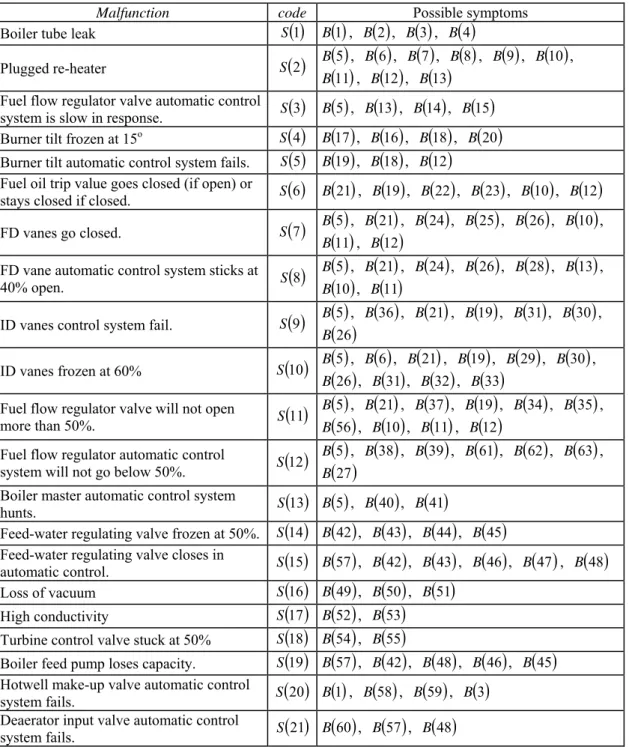
describe the indications of the system. Linguistic variables are the most fundamental elements in human knowledge representation. Table 1 lists some common set of possible indications and Table 2 shows the relationships between fault conditions and possible indications. This database is constructed by operator’s experience and user manual from dealer.
To train a learning machine, the data provided in Table 2 will be used as the training data. There are 63 symptoms used as inputs and 21 malfunctions used as outputs of the learning system, i.e., the learning system is a nonlinear map from ℜ63 toℜ21. Next we
assign numerical values to the training data. Each symptom B
( )
i with 1≤ i≤63 is represented as abinary sequence of length 63 with 1 in ith position and
zero elsewhere. Similarly, each malfunction S
( )
j ,21
1≤ j≤ , is represented as a binary sequence of length 21 with 1 in jth position and zero elsewhere.
Now we briefly describe the training procedure of the support vector machine. Let ℜm denote the
m-dimensional real space, pis
{
1,2,",p}
, nx∈ℜ
is the input vector, and y∈ℜ is the target variable.
Let n
X ⊆ℜ and Y ⊆ℜ. Suppose we are given
the training set
(
)
{
x y}
X Y S l i i i ⊆ × = , =1 : . (1)Let K
( )
x,x' be a given kernel on X×X such that( )
x,x' :( ) ( )
x, x'K = φ φ , x,x'∈X, (2)
where φ is the feature map from the input space X to the feature space F equipped with the inner product
⋅
⋅, [6].
Consider the following maximization problem: Maximize
(
)
∑∑
∑
∑
= = − = = − − l i l j j i j i l i i l i i iy z zzK x x z 1 1 1 1 1 , 2 ε (3) subject to 0 1 =∑
= l i i z , −C≤zi ≤C, i∈l. (4)Suppose z* solves the problem. Then the
optimal predictive function is given by
( )
(
,)
* * 1 * b x x K z x f l i i i + =∑
= , (5) where(
)
∑
= − − = l i k i i k zK x x y b 1 * , * ε (6) for any <zk <C * 0 .3 The goal of machine learning is to solve *
i
z in (3)
and (4) for the construction of the predictive function in (5). In this study we choose C=10, ε=0.01, and the kernel is given by
( )
(
)
⎥ ⎦ ⎤ ⎢ ⎣ ⎡− − =∑
= 63 1 2 2 ' exp : ' , i i i x x x x K σ , 30 2= σ , , '∈ℜ63 x x . (7)The SMO algorithm is utilized to numerically solve the maximization problem [7-8].
The proposed fault diagnostic package can be tested in two ways. On one hand, it can be tested by some realistic experiments under allowed safety condition. On the other hand, computer simulations should be employed if the experiment is expensive or is likely to cause the drastic system damage. The second approach is adopted in this study. The actual hardware of the intelligent fault diagnostic package is shown in Figure 2.
In the first experiment, we test if the learning machine performs well for the training data. Suppose that fault condition S
( )
1 , i.e., boiler tube leak,actually happens, which is caused by purposely dismantling a valve between high-pressure heater and economizer, but the operator of the system does not notice it. Under this circumstance, due to divulge of boiler tube, hotwell water level will decrease gradually and eventually below 50 inches, i.e., symptom B
( )
3 and then symptom B( )
1 can beobserved. At the same time, steam flow will be less than feed water flow and then make-up flow will increase to its maximum, i.e., symptom B
( )
4 andthen symptom B
( )
2 can be observed. In summary,in this experiment, the symptoms will appear in sequence as B
( )
3 -B( )
4 -B( )
2 -B( )
1 . Our real-timefault diagnostic package will display the picture as shown in Figure 3, showing the possibilities of all 21 fault reasons. From the figure, fault S
( )
1 , i.e., boilertube leak, is the most likely fault reason in this experiment, which is consistent with our initial setting.
We wish to point out that small training error of the trained support vector machine does not guarantee good generalization capability, i.e., capability of accurate prediction of previously unseen input. In the second experiment, suppose the symptom sequence
(
B( ) ( )
1 B, 16)
(
B( ) ( )
2 B, 17)
(
B( ) ( )
3 B, 18)
( ) ( )
(
B4 B, 20)
has been observed. Figure 4 showsthe possibilities of all 21 fault reasons. From this figure, faults S
( )
1 and S( )
4 are the most likelyfault reasons for this experiment. The result is consistent with the description in Table 2.
Early warning of possible malfunction is important for safe operation. This can be used as the testing criterion for generalization capability of the trained support vector machine. In the third experiment, suppose FD vanes actually go closed S
( )
7 but onlysymptoms B
( )
5 , B( )
21 , B( )
24 , and B( )
25 havebeen observed. Figure 5 shows the possibilities of all 21 fault reasons. From this figure, it is clear that fault S
( )
7 is the most likely fault reason in thisexperiment. From Table 2, we see that correct detection can also be made if only partial set of symptoms in S
( )
7 are available.In this study, an intelligent fault diagnostic package for the oil-fired power plant with turbine generator by using support vector machine has been developed. This package is able to predict in real time the most likely fault reasons based on symptoms available. Based on the prediction results, appropriate maintenance planning can be made before the machine actually breaks down. Real-case studies have also been made to demonstrate the use of our package. From the experimental results, the performance of our intelligent package shows promising potential as a diagnostic tool for early warning of power breakdown for an oil-fired power plant. 四、計畫成果自評 本計畫之執行可對本國於海運研究領域中的 學術地位加以提昇;同時也為少數針對現有船舶系 統智慧型故障診斷的研究,其研究成果將可提供本 國造船業界於船舶問題實務化之提昇。因此本計畫 可同時提供理論及實務應用之研究資源。 在研究計畫中,吾人成功地利用機器學習理架 構出一個船用燃油式蒸汽動力場之智慧型故障診 斷器,並利用個人電腦之介面配合簡單的硬體電路 發展出一個適合教學用途之故障診斷訓練器。經由 實驗證實本計畫提出之訓練器可在(1)完整故障訊 號出現時,(2)僅有部份故障訊號出現時,(3)多重故 障原因出現時均可正確的判斷故障原因。因此在本 計畫所提出的診斷系統應用於實際之船用燃油式 蒸汽動力場可視為一組真正的故障診斷器。 本計畫的開發軟體是使用 visual basic 6.0 設 計,同時也考慮到單一軟體模擬;換言之,即使沒 有硬體電路環境也可進行軟體模擬分析之用途。 五、參考文獻
[1] P. M. Frank, “Fault detection in dynamic systems using analytical and knowledge based redundancy--a survey,” Automatica, vol. 26, no. 3, pp. 459-474, 1990.
[2] R. Isermann, “Process fault detection based on modelling and estimation methods--survey,”
Automatica, vol. 20, no. 4, pp. 387-404, 1984.
knowledge-based system for turbine generator fault diagnosis,” Artificial Intelligence in
Engineering, vol. 10, pp. 335-341, 1996.
[4] S. Poyhonen, M. Negrea, A. Arkkio, H. Hyotyniemi, and H. Koivo, “Fault diagnostics of an electrical machine with multiple support vector classifiers,” in Proc. 2002 IEEE
International Symposium on Intelligent Control,
Vancouver, Canada, 2002, pp. 27-30.
[5] B. E., Boser, I. M. Guyon, and V. N. Vapnik, “A training algorithm for optimal margin classifiers,” in Proc. Fifth Annual Workshop on
Computational Learning Theory, Pittsburgh,
Pennsylvania, United States, 1992, pp. 144-152. [6] N. Cristianini and J. Shawe-Taylor, An
Introduction to Support Vector Machines.
Cambridge, United Kingdom: Cambridge University Press, 2000.
[7] J. Platt, “Fast training of support vector machines using sequential minimal optimization,” in: B. Schölkopf, C.J.C. Burges, A.J. Smola (Eds.), Advances in Kernel
Methods-Support Vector Learning.
Cambridge, MA: MIT Press, 1999, pp. 185-208. [8] M. A. Hearst, S. T. Dumais, E. Osman, J. Platt, and B. Schölkopf, “Support vector machines,”
IEEE Intelligent Systems, vol. 13, no. 4, pp.
18-28, 1998.
Fig. 1. Oil-fired power plant with turbine generator.
Fig. 2. The actual hardware of the intelligent fault diagnostic package.
Fig. 3. Experiment result of malfunction S
( )
1 .Fig. 4. Experimental result when malfunctions S
( )
1and S
( )
4 occur at the same time.Fig. 5. Experimental result of malfunction S
( )
75
Table 1. Symptoms of alarm or indication
Possible alarm and indication code Possible alarm and indication code
Low hotwell level at 50” B
( )
1 Airflow remains at 60% vane openingequivalent to about 55% airflow. B
( )
33 Make-up flow increases to maximum. B( )
2 Fuel flow automatic control signalincreases to maximum. B
( )
34 Hotwell level decreases. B( )
3 Fuel flow will not go above 50%. B( )
35Steam flow less than feed flow B
( )
4 Furnace pressure high at 3.5” H2Ometer B
( )
36 Smoke condition at 20% B( )
5 Reheater temperature low at 950oF B( )
37High furnace pressures 7” B
( )
6 Main steam pressure high at 1950 psig B( )
38ID fan vanes automatic control signal will
slowly increase to 100%. B
( )
7 Safety valves lift at 1975 psig B( )
39 When ID fan vanes are open to maximum,furnace draft will slowly go positive. B
( )
8 Boiler master control signal oscillates. B( )
40 Airflow through boiler will decrease belownormal. B
( )
9Fuel and fan automatic control signals follow variations of boiler master control signal.
( )
41B
Main stream temperature will decrease. B
( )
10 Low drum level at 3.5” B( )
42Main stream pressures will decrease. B
( )
11 Feed regulator valve automatic controlsignal increases to maximum. B
( )
43 Reheater temperature will decrease. B( )
12 Feed-water flow holds at 50%. B( )
44Improper oil to air ratio B
( )
13 Drum level slowly decreases. B( )
45Fuel flow lags behind and boiler master control
system demand signal when load change. B
( )
14 Feed-water flow decreases to zero. B( )
46 Fuel flow eventually settles at proper level atsteady state. B
( )
15 Deaerator level increases. B( )
47 Reheater temperature increases. B( )
16 Hotwell level increases. B( )
48Reheater temperature high at 1050oF B
( )
17 Low vacuum at 25” Hg. B( )
49Burner tilt automatic control system signal
goes –30o. B
( )
18 Vacuum slowly drops. B( )
50 Turbine vibration at 100oF differential betweenreheater and turbine metal item B
( )
19 Vacuum holds at 50% load. B( )
51 Burner tilt automatic control system signal noresponse B
( )
20 High conductivity alarm at 1 micromho B( )
52 Low main steam temperature at 950oF B( )
21 Conductivity increases slowly. B( )
53Boiler master automatic control signal increases
to maximum. B
( )
22 Turbine control valve auto will not above 50%. B( )
54 Steam pressure starts to drop suddenly. B( )
23 Turbine control valve in manual willnot above 50%. B
( )
55 FD vane automatic control system signal goes tomaximum. B
( )
24 Airflow increases to value corresponding to firing rate. B( )
56 ID vane automatic control signal slowlydecreases to approximately 20% in order to maintain proper furnace draft.
( )
25B High hotwell level at 70” B
( )
57Airflow decreases. B
( )
26 Make-up valve automatic controlsignal increases to maximum. B
( )
58 Steam pressure increases. B( )
27 Make-up flow decreases to zero. B( )
59ID vane automatic control signal holds at 40%. B
( )
28 Low hotwell level at 50” B( )
60ID vane automatic control signal increases to maximum. B
( )
29Boiler master firing rate decreases below 50%. B
( )
61 Furnace pressure draft goes positive. B( )
30 Fuel flow automatic control signalfollows firing rate signal. B
( )
62 ID vane automatic control signal slowlydecreases to 0%. B
( )
31 Fuel flow stops decreasing at 50%. B( )
63 Furnace pressure draft goes negative. B( )
326
Table 2. Faults and possible symptoms
Malfunction code Possible symptoms
Boiler tube leak S
( )
1 B( )
1 , B( )
2 , B( )
3 , B( )
4Plugged re-heater S
( )
2 B( )
( )
5 , B( )
6 , B( )
7 , B( )
8 , B( )
9 , B( )
10 , 11B , B
( )
12 , B( )
13Fuel flow regulator valve automatic control
system is slow in response. S
( )
3 B( )
5 , B( )
13 , B( )
14 , B( )
15 Burner tilt frozen at 15o S( )
4 B( )
17 , B( )
16 , B( )
18 , B( )
20Burner tilt automatic control system fails. S
( )
5 B( )
19 , B( )
18 , B( )
12Fuel oil trip value goes closed (if open) or
stays closed if closed. S
( )
6 B( )
21 , B( )
19 , B( )
22 , B( )
23 , B( )
10 , B( )
12 FD vanes go closed. S( )
7 B( )
( )
5 , B( )
21 , B( )
24 , B( )
25 , B( )
26 , B( )
10 ,11
B , B
( )
12FD vane automatic control system sticks at 40% open. S
( )
8( )
5B , B
( )
21 , B( )
24 , B( )
26 , B( )
28 , B( )
13 ,( )
10B , B
( )
11ID vanes control system fail. S
( )
9 B( )
( )
5 , B( )
36 , B( )
21 , B( )
19 , B( )
31 , B( )
30 , 26B
ID vanes frozen at 60% S
( )
10 B( )
( )
5 , B( )
6 , B( )
21 , B( )
19 , B( )
29 , B( )
30 , 26B , B
( )
31, B( )
32 , B( )
33Fuel flow regulator valve will not open
more than 50%. S
( )
11( )
5B , B
( )
21 , B( )
37 , B( )
19 , B( )
34 , B( )
35 ,( )
56B , B
( )
10 , B( )
11 , B( )
12Fuel flow regulator automatic control
system will not go below 50%. S
( )
12( )
5B , B
( )
38 , B( )
39 , B( )
61, B( )
62 , B( )
63 ,( )
27B
Boiler master automatic control system
hunts. S
( )
13 B( )
5 , B( )
40 , B( )
41Feed-water regulating valve frozen at 50%. S
( )
14 B( )
42 , B( )
43 , B( )
44 , B( )
45Feed-water regulating valve closes in
automatic control. S
( )
15 B( )
57 , B( )
42 , B( )
43 , B( )
46 , B( )
47 , B( )
48 Loss of vacuum S( )
16 B( )
49 , B( )
50 , B( )
51High conductivity S
( )
17 B( )
52 , B( )
53Turbine control valve stuck at 50% S
( )
18 B( )
54 , B( )
55Boiler feed pump loses capacity. S
( )
19 B( )
57 , B( )
42 , B( )
48 , B( )
46 , B( )
45Hotwell make-up valve automatic control
system fails. S