Pattern Recognition, Vol. 28, No. 4, pp. 493-512, 1995
Elsevier Science Ltd Copyright @ 1995 Pattern Recognition Society Printed in Great Britain. All rights reserved @X-3203/95 $9.50 + .CKI
0031-3203(94)00122-7
A CHINESE-CHARACTER
THINNING ALGORITHM BASED
ON GLOBAL FEATURES AND CONTOUR INFORMATION*
JENN-YIH LIN and ZEN CHENtInstitute of Computer Science and Information Engineering, National Chiao Tung University, Hsinchu, 300, Taiwan, R.O.C.
(Received 23 November 1993; in revised form 30 August 1994; received for publication 14 September 1994) Abstract-This paper proposes a method of using run-length coding to perform thinning. First, we construct graphs from characters. The attributes (vertical lines, horizontal lines or points) of each node in the graph are determined according to the node’s relationship to the nodes above and below it (we will refer to these relationships as global features) and the black runs within the node. Intersections between two adjacent segments are determined on the basis of the graph constructed and contour information. The thinning algorithm thus employs global features and contour information to produce a more accurate skeleton.
Thinning Run Run-length coding
1. INTRODUCTION
Many character thinning algorithms have been pro- posed in the past two decades. Suen et al.“’ surveyed more than 100 thinning methods and classified them into two groups: methods based on iterative deletion of pixels and nonpixel-based methods. Many methods based on iterative deletion of pixels employ a window operator for thinning. These methods place a 3 x 3, 5 x 5, or larger n x n window onto the image and then use a look-up table to determine whether to retain or delete the center black pixel. Some methods even use a window larger than 5 x 5 (such as the method which uses a 9 x 9 window),“) but they make rough decisions in certain cases to reduce the amount of memory needed and the search time.
In general, the advantages of using a window operator to perform thinning are that this approach is simple and can easily be implemented as a parallel algorithm. The disadvantages are that this method is relatively sensitive to noise and that it is less effective than other methods in processing the cross sections of a character. To overcome this second disadvantage, Suen et ~1.‘~) extracted ten different cross sections for further thinning and then substituted the thinning result obtained for the thinning result of the method in reference (4).
One type of nonpixel-based method is to employ run-length coding for thinning. This approach is almost used for character thinning.“-” This method divides a character into a number of segments (a segment is
* This study was supported by the National Science Council, Republic of China, under contract number NSC83-0408-E- 009-009.
t To whom all correspondence should be addressed.
Stroke extraction Skeleton
composed of several connected black runs). The seg- ments and their connections are then used to deter- mined how the segments will be thinned. In refer- ence (5) the merge and fork relationships between runs were used to convert characters into compressed line adjacency graphs (henceforth, “c-LAG”). If there was a significant change in the width of the runs of a node in the graph, the node was divided into a horizontal stroke and a vertical stroke. Vertical strokes with approximately constant width and nearly collinear centerpoints were denoted “candidates for vector- ization”. Finally, compound vectorization was used to generate the final result. In reference (6), it was assumed that the width of the lines in a character was approxi- mately constant. Merges, forks and significant changes in width in runs were used to construct graphs from characters. Relatively short nodes were regarded as noise and deleted. The line segments in each node were divided into horizontal strokes and vertical strokes; stroke extraction was then performed to obtain the final result. In reference (7), the line segments in Chinese characters were classified into four primitive types of strokes: horizontal strokes, vertical strokes, up-right- slanting strokes, and up-left-slanting strokes. On the basis of knowledge of the structure of Chinese charac- ters, twenty parameters were derived to distinguish between these four primitive strokes. These parameters were then used in the stroke extraction procedure to determine to what type of stroke each line segment belonged.
One recent paper@) used run-length coding to perform thinning of objects with similar widths. The main aim of this method is to preserve an x-crossing skeleton. It is assumed that the objects in the image are lines or curves of similar width (say, h). If the length of a
494 J.-Y. LIN and Z. CHEN
column (row) run is less than 1.2 h, then the midpoint of that run is used to form the skeleton. If the length of a column (row) run is greater than 1.2 h, the clusters of the “long” runs are located, which are found at line intersections or vertical lines. If they are line intersec- tions, the skeletons of the intersections are found using heuristic rules. The column-wise result and the row- wise result are then combined to obtain the final result.
One disadvantage of using a window operator in preprocessing for Chinese character recognition is that much information can be evaluated more easily before thinning takes place. Important information about connecting strokes and touching strokes, for example, may be completely lost when a window operator is used to perform thinning (see Fig. 1). When run-length coding is used to perform character thinning (charac- ters are decomposed into strokes only), on the other hand, the structure of the original character is preserved. Most Chinese characters are composed of vertical lines, horizontal lines and slanted lines. In theory, using run-length coding to perform thinning should produce acceptable results. The presence of noise, con- necting strokes, touching strokes and variations in width along the length of a stroke (in printed charac- ters), however, creates segment combinations of many different shapes and hence greatly increases the dif- ficulty of using run-length coding to perform thinning.
At present, the most common drawbacks associated with using run-length coding to perform thinning of Chinese characters are as follows:
(1) the shape of a segment is evaluated on the basis of the runs containing that segment only (or some cases the nearest run in an adjacent segment). Yet using only local information such as this can easily lead to
erroneous results, because completely identical seg- ments appearing in different positions may in fact represent different shapes;
(2) the graph constructed and the boundaries of the character shape are not properly utilized to evaluate the relationship between segments, such as whether two adjacent segments intersect or whether a segment lying on a horizontal line is connected with the right or left end of the line;
(3) the treatment given to regions of intersection is too rough. In Chinese characters there are many different types of intersecting shapes and touching strokes, which may intersect at a single point, along a vertical line, or along a horizontal line. In some cases, even two hori- zontal lines may touch;
(4) using each node in the constructed graph to re- present one stroke in a Chinese character is not a very sound approach. For example, in some cases, a short segment lying above (or below) a horizontal line should be joined to the horizontal line. If this short segment is regarded as an independent line, an erroneous skel- eton will be produced (see the discussion of graph modification in Section 4).
This paper will propose a method of using run- length coding to perform thinning. The attributes (vertical lines, horizontal lines or points) of each node in the graph are determined according to the node’s relationship to the nodes above and below it (we will refer to these relationships as global features) and the runs within the node. In this way, the correct attributes of identical segments in different positions can be ob- tained by examining the relationships between the nodes and the nodes above and below them. Inter- sections between two adjacent segments are determined
.= Touching stroke
A Chinese-character thinning algorithm based on global features and contour information 495
on the basis of the graph constructed and contour information. This thinning algorithm thus employs global features and contour information to produce a more accurate skeleton.
The remainder of this paper is organized as follows. In Section 2, we describe the process of graph construc- tion. Node attributes and their relationships are de- scribed in Section 3; the graph modification process is described in Section 4. In Section 5, the thinning algor- ithm is presented. In Section 6, experimental results are presented that confirm the effectiveness of the proposed thinning process. Section 7 concludes the paper.
2. GRAPH CONSTRUCTION
A Chinese character comprises one or more discon- nected components, each of which is composed of one or more strokes. In practice, the connections between these strokes can be classified into the following types, which we have identified from experiments:
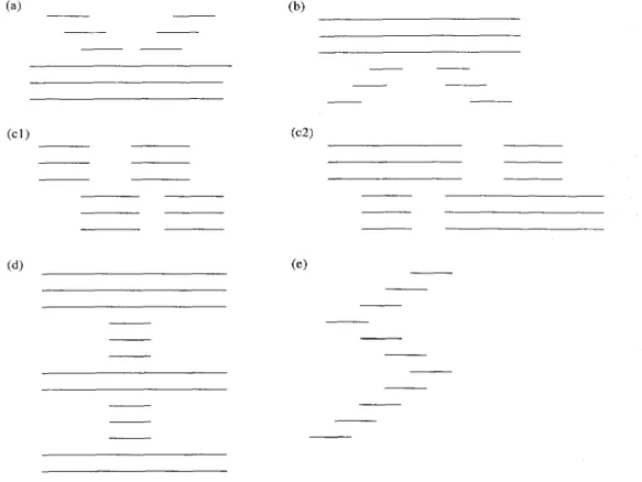
(1) merge: two or more strokes merge into a single stroke [see Fig. 2(a)];
(2) fork: a single stroke forks into two or more strokes [see Fig. 2(b)];
(3) A combination ofmerges and forks [see Fig. 2(c)]; (4) there is a significant change in width between adjacent strokes [see Fig. 2(d)];
(5) the centerpoints of adjacent strokes are not col- linear [see Fig. 2(e)].
Because of the effects of noise, the width of the runs in the stroke types described above may not be constant. Except for the first and the last runs, we require that the changes in the width of the runs remain within a certain threshold.
In the following we will employ the stroke connections set forth above to construct the graphs of a character. In the following, if not specified ohterwise, the term “run” denotes a black run.
2.1. Features and nodes
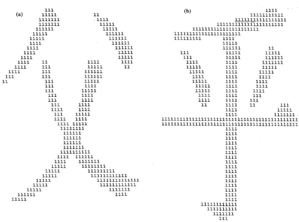
In this paper, every run will be classified as represent- ing one of the following features: starting run, fork, merge, end run, or follower. These features are described in detail below (see Fig. 3):
(1) starting run: a run that is not connected to any other run above it is considered a starting run;
(2) fork: a run that connects to two or more runs below it is classified as a fork;
(3) merge: a run connected to two or more runs above it is considered a merge;
(4) end run: a run that is not connected to another run below it is classified as an end run;
(5) follower: a run that is connected to a single run above it and another below it is classified as a follower.
(a) (b)
(Cl) (c2)
Cd) (e)
Fig. 2. Examples of connections between two or more strokes. (a) Merge; (b) Fork; (c) A combination of merges and forks; (d) A significant change in width between adjacent strokes; (e) The centerpoints of adjacent
496 J.-Y. LIN and Z. CHEN
Starting run ==5 <== Starting run (top)
<== Merge (third)
<== Fork (fifth)
End run ==> <== End run (last)
Fig. 3. Types of features (runs for which no feature is specified arc followers).
Fig. 4. Graph for Fig. 3.
The runs between any two features (excluding fol-
\ lowers) are regarded as nodes. Nodes may have one of three attributes: vertical line, horizontal line or point. (note: below we use line-fitting to perform thinning. For vertical lines, the centerpoints of the horizontal black runs are used to obtain a line equation. For horizontal lines, the centerpoints of the vertical black runs are used to obtain a line equation. For points, fitting is not necessary.) Figure 4 is the graph of Fig. 3. The information contained in the nodes of a graph includes the following:
(1) the number of runs;
(2) the x-axis and y-axis coordinates of the leftmost point of each run and the width of the run;
(3) the attribute of the node (vertical line, horizontal iine, or point);
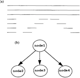
(4) how many nodes there are above and below the node under consideration and the relationships between these nodes (see Fig. 5);
(5) the value of the label (the runs in different nodes will be labeled with different values).
For example, in Fig. 5, the node relationships are as follows: Node 1 has no nodes above it, but three nodes below it (nodes 2,3 and 4). Node 2 is connected to the left end of node 1, but not to the right end. Nodes 2 and 3 do not intersect; nodes 3 and 4 intersect. Node 4 is not connected to the right end of node 2. Nodes 2, 3 and 4 each have one node above them (i.e. node 1) and no nodes below them.
2.2. Processing offeatures
During the scanning process, each time a feature is encountered in the scanned image, information about the feature is recorded in the corresponding node. The action of every feature and the information recorded are described beiow.
(a)
(b)
Fig. 5. (a) Run figure; (b) Graph. The node relationships are as follows: node 1 has three nodes below it; node 2 is connected to the left end of node 1, nodes 3 and 4 intersect; node 4 is not connected to the right end of node 1; nodes 2, 3 and 4 each
have one node above them.
2.2.1. Starting runs. When a particular run is identi-’ fied as a starting run, the following procedures are performed:
(11 a new node is established; \m, -~ ~~~
(2) the x-axis and y-axis coordinates bf the leftmost point of the run and the width of the run are recorded in the node;
(3) the run is assigned a new label;
(4) the value of the label is saved in the node; (5) the run count for the node is set to 1.
2.2.2. Followers. When a run is identified as a fol- lower, the following procedures are performed:
(1) the x-axis and y-axis coordinates of the leftmost point of the run and the width of the run are recorded in the same node as the run above it;
(2) the run is labeled with the same label as the run above it;
(3) the run count for the node in which the run is saved is incremented by one.
2.2.3. End runs. When an end run is identified, we need to determine whether the node it is in, is formed of several strokes [see Fig. 2(d) and (e)] and to eliminate noise around the end run.
A Chinese-character thinning algorithm based on global features and contour information 497 In order to divide a node into several strokes, we
assume every stroke is composed of at least two runs. If a node contains only one run, we merge it into a node above or below it (see Fig. 6), or else we regard it as noise and delete it.
To divide the runs in Fig. 2(d) into five strokes, we take four runs at a time and determine whether the four can be divided into two strokes. Let the widths of runs i, ifl, i+2, and i+3, be Wi, Wi+r, Wi+z and W+3r respectively. If equation (2.1) holds, then the runs up to (and including) run i + 1 form one stroke, and those from run i + 2 on form a different stroke.
(2* Wi < Wi+* and 2* W,+r < Wi+3) and (Wi + thresh1 < Wi+z and Wi+l
+ thresh1 < Wi+3) and ~I~+~~wil+IWi+3~~+2l~I~+2~Wi+II~
(2.1) In equation (2.1), the expression in the first set of parentheses indicates that the width of the wider runs
2222222 2222222 2222222 33333333333 444444444444444444 444444444444444444 444444444444444444
Fig. 6. The run labeled 3 is merged into either group 2 or group 4. 1 11 111 Cd , 11111 1111111 1111 1111111 11111 111111 11111 11111 111111 11111 111111 1111 111111 1111 111111 1111 11111 1111 11111 1111 11 1111 1111 1111 111 11111 11 1111 111 111111 11 111 111111 111 11111 111 1111 111 11111 111 1111 111 1111 111 1111 1111 1111 111 11111 1111 1111 1111 11111 11111111 111111 111111 111111 1111111 1111111111 1111 111111 1111 1111111 11111 11111111 11111 111111111 11111 111111111111 11111 11111l.l.1111111 11111 111111111111 11111 1111111 111111 1111 11111
is two or more times that of the narrower runs. The expression in the second set of parentheses is included to prevent the width of the narrower runs from being too narrow (such as a width of only 1 or 2) and hence producing a mistaken result. The expression in the third set of parentheses is included to prevent a single stroke from being divided into two strokes in cases where the width of the end of a stroke is larger than the width of the rest of the stroke (see Fig. 7).
Equation (2.1) applies to cases where the change in the width of successive runs is from narrow to wide. In cases where the width changes from wide to narrow, the following equation is used to divide the runs into separate strokes:
(2* Wi+2 < Wi and 2* Wi+3 < W,+l) and (Wi+z + thresh1 < Wi and Wi+3
+ thresh1 < Wi+ 1) and
(IW+1-~l+IW+3-
wi+Zl < Iwi+Z - wi+il)
(2.2)
Once we have used the above equations to determine whether the first group of four runs can be divided into two strokes, we continue to work downward until we have covered all of the runs.In some cases, the runs in a node should be divided into two strokes, but because of the effects of noise, they may in fact fail to be divided. For example, in Fig. 6, if the width of run 3 is less than twice that of group 2 but more than half that of group 4, then the
(b) 1111 11111111111 L/~~~~1111111111 1111111111111111111111 1111111111111111111111 1111111111111111111111 111111111 1111 11111 111 111111 11 11111 11111 111 11111 111111 1111 1111 1111111 11111 1111 11111 11111 1111 11111 1111 1111 1111 11111 1111 1111 11111 1111 1111 11111 1111 1111 1111 1111 111 1111 1111 111 11 1111 11 111 1111 11111 1111 1111111 111111111111111111111111111111111111111111111 111111111111111111111111111111111111111111111 1111 1111 1111 1111 1111 1111 1111 1111 1111 1111 1111 1111 1111 1111 1111 1111 111111111111 1111111111 1111111 111
498 J.-Y. LIN and Z. CHEN
method described above will fail to divide the runs in Fig. 6 into two strokes. Hence after the above decision method is applied, we check to see whether the number of runs in a stroke is greater than five. If it is, the decision procedure is repeated, this time using groups of five runs instead of groups of four. Suppose that the widths of five runs, from top to bottom, are Wi, Wi+ l, Wi+z, Wi+ 3 and Wi+4, respectively. Then Wi+ 3 and Wiy4 are substituted for Wi+z and Wi+3, respectively, in Equations (2.1) and (2.2), and the stroke division procedure is repeated. If one of the equations holds, then the group of runs must be further subdivided, and run Wi+2 is considered to be a part of the group of longer runs.
To delete noise, at this stage of the procedure we merely delete any nodes consisting of a single run. Any remaining noise is eliminated using the procedure de- scribed in Section 4 below.
In summary, when a run is identified as an end run, the following procedures are performed:
(1) if the run can also be identified as a starting run, then the node is regarded as noise and deleted (it is merely a short black run);
(2) if the feature above the run is a fork, then the node in which the current run is located is deleted;
(3) We check whether the node in which the run is located can be divided into two or more different strokes [see Figs 2(d) and (e)]. If it can, then we divide it, save each stroke as an individual node, and reassign the nodes that were above or below the original node so that they connect to the new nodes.
2.2.4. Forks. When a fork is identified during the scanning procedure, the following procedures are per- formed:
(1) The fork node is checked to see whether it can be divided into two or more strokes using a procedure analogous to that described in Section 2.2.3;
(2) in a procedure analogous to that for starting runs, a node is created for each run after the fork and these nodes are inserted below the node that contains the fork run.
2.2.5. Merges. When a merge is found, the following procedure is performed:
Step 1. the nodes before the merge are checked and any node with a run count of one is deleted. If after this step is performed no nodes are left above the merge, then the run being scanned is identified as a starting run.
Step 2. if after step 1 there are nodes remaining above the merge, then each node is checked to see if it can be further subdivided into new nodes [see Fig. 2(d) and (e)]. If so, the node is divided and the nodes above and below it are reassigned to connect to the new nodes. Step 3. (1) if after step 2, the number of nodes preced- ing the merge is one, then the current run is identified as a follower;
(2) if the number of nodes is more than one, then a
new node is created and the node preceding the merge is inserted above this node.
2.2.6. Graph construction algorithm. Our graph construction procedure can be summarized by the following algorithm:
Step 1. scan a bilevel image from left to right and top to bottom. When one of the following cases is found to hold, go to step 2.
Case 1. the first pixel scanned is a white pixel; con- tinue scanning rightward until a non-white pixel or the end of the row is reached.
Case 2. the first pixel scanned is a black pixel; con- tinue scanning rightward until a non-black pixel or the end of the row is reached.
Step 2. process the two cases in step 1.
Case 1. in step 1, a white run was scanned. Now check whether a previously labeled run appears above this white run;
(1) if yes, then label each labeled run as an end run; (2) if no, then go to step 4.
Case 2. In step 1, a black run was scanned. Now check whether a previously labeled run appears above this black run.
(1) if no, then label the currently scanned black run as a starting run;
(2) if two or more labeled runs appear above the current black run, then label the current run as a merge and check whether the rightmost labeled run connected to the run below is a fork run [see Fig. 2(c.l)]. If yes, insert these nodes below the node that the rightmost labeled run is in;
(3) if only one labeled run appears above the current run, then check how many non-white runs in the scanning row are connected to the above labeled run; (a) if there is only one, then label the currently scanned run as a follower;
(b) if there are two or more, then label the run above as a fork and check whether the rightmost black run connected to the run above is a merge run [see Fig. 2(c.2)]. If yes, insert these nodes above the node that the rightmost black run is in.
Step 3. once a run has been labeled as a starting run, fork, merge, follower, or end run in step 2, execute the processing described in the subsections above for the corresponding type of label.
Step 4. Check whether the scanning process has reached the rightmost pixel in the last line of the image.
(1) if yes, then go to step 5.
(2) if no, then check whether the scanning process has reached the last pixel in the current row;
(a) if no, then go to step 1 and continue scanning rightward;
(b) if yes, then move to the first pixel in the next row, go to step 1 and begin scanning rightward.
A Chinese-character thinning algorithm based on global features and contour information 499
3. NODE ATTRIBUTES AND NODE RELATIONSHIPS In this section, we shall discuss two topics:
(1) node attributes: each node is assigned one of three attributes: vertical line, horizontal line, or point;
(2) node relationships: whether the adjacent nodes intersect or whether the nodes above or below the node under consideration are connected on the left end or right end with the node under consideration (see Fig. 5).
3.1. Node attributes
Nodes may have one of three attributes: vertical line, horizontal line or point. Unless the ratio of a node’s width to its height is very large, in which case the node is definitely a horizontal line, we must examine a par- ticular node’s relationship to other nodes above and below it in order to identify the attribute of the node. If we attempt to identify node attributes on the basis of only the run information contained in the nodes, then the risk of error is very high. In the following discussion, we use the parameter “up” to indicate the number of nodes a particular node is connected with above it and the parameter “dn” to indicate the number of nodes a node is connected with below it. Our guidelines for identifying the attributes of nodes are described below.
First we define a series of conditions. (Note: in each of the following, “Cond i” indicates the condition expressed by the words outside the parentheses, while “Cond i(a)” indicates the condition expressed by the words in parentheses.)
Cond l(a): the location where the node under con- sideration is connected to the node above (below) is not the first (last) run of the node under consideration (see Fig. 8).
Cond 2(a): the node under consideration is connected to only a single node above (below) it, and the width of the first (last) run of the node under consideration is wider than that of the last (first) run of the node above (below) it plus threshl.
Cond 3(a): the node under consideration is connected to” two or more nodes (assume n nodes) above (below) it, the width of the node under consideration is more than twice its height, and the width of its first (last) run is greater than the sum of the widths of the last (first) runs of all nodes above (below) it plus (n + threshl).
Cond 4(a): the run count of the node under con- sideration is less than thresh3 and the widths of the runs are strictly decreasing (increasing) (this criterion can be relaxed to allow several runs to have equal width).
2222
Case 1. up = 0 and dn = 0:
This indicates that the node under consideration is an isolated node. If the ratio of the maximum width of the runs to the height of this node is greater than 1, then the node is a horizontal line; otherwise, it is a vertical line.
Case 2. (up = 1 and dn = 0) or (up = 0 and dn = 1) this indicates that if the node is not a horizontal line, it is a vertical line. Consider up = 1, dn = 0 as an example:
(a) if the node above the node under consideration is connected to more than one node below it, then the node under consideration is a vertical line;
(b) if Cond 1 or Cond 2 holds, then the node under consideration is a horizontal line;
(c) if neither (a) nor (b) holds, then the node is a vertical line.
An analogous algorithm can be used on up = 0 and dn=l.
Case3. up=landdn=l
This indicates that if the current node is not horizontal line, it is a vertical line.
(a) if the node above the current node is connected to more than one node below it, and the node below the current node is connected to more than one node above it, then the current node is a vertical line.
(b) if Cond 1, Cond l(a), Cond 2, or Cond 2(a) holds, then the current node is a horizontal line;
(c) if neither (a) nor (b) holds, then the node is a vertical line.
Case 4. (up 2 2 and dn = 0) or (up = 0 and dn 2 2) the current node may be a horizontal line, vertical line, or a point. Consider up 2 2, dn = 0 as an example:
(a) if Cond 1 or Cond 3 holds, then the current node is a horizontal line;
(b) if Cond 4 holds, then the node is a point; (c) if neither (a) nor (b) holds, then the node is a vertical line.
Case 5. (up 2 2 and dn = 1) or (up = 1 and dn 2 2) the current node may be a horizontal line, vertical line, or a point. Let us consider up 2 2, dn = 1 as an example:
(a) if Cond 1, Cond l(a), Cond 2(a), or Cond 3 holds, then the current node is a horizontal line;
(b) if Cond 4 holds, then the node is a point; (c) if neither (a) nor (b) holds, then the node is a vertical line.
2222 33333
2222 3333333333 2222 33333333333
3333333333333333333 <== Intersection run (fourth) 3333333333333333333333
3333333333333333333333333
500 J.-Y. LIN and Z. CHEN
Case6. up22anddn22
the current node may be horizontal line, vertical line, or a point.
(a) if Cond 1, Cond l(a), Cond 3, or Cond 3(a) holds, then the current node is a horizontal line;
(b) if the widths of the runs in the current node are strictly decreasing followed by strictly increasing and the run count is less than thresh3, then the node is a point (this criterion can be relaxed to allow several runs to have the same width);
Step 3. find the largest y-axis coordinate among the coordinates of all the runs in node (i - 1) and node (i) and denote it by y,;
Step 4. if ly, - yPl I thresh2, node (i - 1) and node (i)
intersect. Otherwise, node (i - 1) and node (i) do no intersect.
4. GRAPH MODIFICATION
(c) if neither (a) nor (b) holds, then the node is a vertical line.
After we have determined the attributes of every node and the relationships between nodes, we further modify and reline the graph in the following ways:
3.2. Relationships between nodes
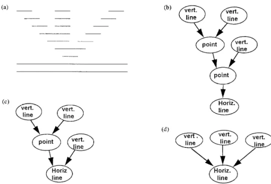
During the thinning process, we need to know whether the left ends (right ends) of strokes formed by two nodes one above the other are connected and whether strokes formed by adjacent nodes intersect. If the strokes do intersect, we need to lit them so that they intersect at one point in order to produce a correct skeleton.
(1) Noise is eliminated as follows: if a vertical line located directly above (below) a horizontal line is found to be unconnected to any node above (below) it and the height of the vertical line is less than half the height of the horizontal line, then the vertical line is deleted.
(2) If a horizontal line is connected to a point above (below) it, the point is deleted [see Fig. 9(c)]. If, after the point is deleted, other points are found, these too are deleted [see Fig. 9(d)].
When identifying node relationships, we need only to consider nodes that represent horizontal lines. This is because if nodes that are vertical lines or points are connected to two or more nodes above (below), then the nodes above (below) will definitely intersect.
(3) If two horizontal lines are connected together and the difference in the slope of the lines is negligible, the two lines are merged into a single horizontal line.
Before identifying the relationships between nodes, we must first delete any noise above and below vertical lines [see labels 5 and 9 in Fig. 13(cl)].
(4) To facilitate the processing described in Section 5 below, when a vertical line is connected to two or more vertical lines above (below) it, we add a “point” node between the vertical line and the vertical lines above (below) it (see Fig. 10).
Suppose node A is a horizontal line, and let node B be the rightmost node above node A to which node A is connected. The following algorithm (algorithm 1) is designed to determine wheter these nodes are connected on the right end (an analogous algorithm can be used to check whether the left end is connected).
5. THINNING
Algorithm 1:
Step 1. find the run in node A that has the largest value
for its x-axis coordinate and denote it by xi. Denote its y-axis coordinatee by y,;
Step 2. find the line equation of the line formed by the
rightmost point of each run in node B;
Step 3. obtain the value of x2 by substituting y1 into the line equation found in step 2.
Step 4. if lx2 -x11 5 2, then the right end of these
nodes is connected; otherwise, they are not connected on the right.
We have now completed our description of the stroke extraction process and shown how the attributes of each stroke and the relationships between strokes are identified. In this section, we shall describe how the data derived through the processes outlined in Sections 2, 3, and 4 may be used to obtain a character skeleton.
Our approach will be to construct the skeleton of a character by performing line fitting using the attributes of and relationships between nodes in the character graph. For horizontal lines, we shall use the center- points of vertical runs for line fitting. For vertical lines, we shall use the centerpoints of horizontal runs for line fitting. The steps in the process are as follows:
Suppose node A is a horizontal line. If there are n (> 1) nodes above node A that are connected with it, the following algorithm (algorithm 2) can be used to determine whether node (i - 1) and node (i) intersect. Algorithm 2:
Step 1. use line fitting to find the line equation of the
line formed by the centerpoints of each run in node (i - 1) and that formed by the centerpoints of each run in node (i);
Step 1. we begin by fitting all horizontal lines. If the
left end or right end of a horizontal line is a connected to a vertical line, then the horizontal line is fitted to half the average line width of the vertical line. The coordinates of the left and right end points of the horizontal line after fitting are then recorded;
Step 2. all points are masked out (fitting is not per-
formed on points), with the centerpoint of each point being used to represent the location of the point. The coordinates of the centerpoints are then recorded;
Step 3. we repeat step4 through step 7 until all vertical
lines have been fitted;
Step 2. find the intersection of the two lines in step 1 Step 4. we identify a node of a vertical line that has
A Chinese-character thinning algorithm based on global features and contour information 501 (b) Cc) vert. line
9
vert. line vert.SF
point ine point (4Fig. 9. (a) Run figure; (b) Graph; (c) We delete the point node above a horizontal line node; (d) After (c), if there is still a point node in the horizontal line node, it is also deleted.
(a) (b) vet-t. vet-t. line line
YP
vet-t. a line (c) vet-t. line13
0
vert. line /- point z vet?. lineFig. 10. (a) Run figure; (b) Graph; (c) We add a “point” node between the two existing nodes.
Step 5. for the line identified in step 4, we determine how many collinear vertical lines there are above it and below it. We regard these lines as forming a set, which we will call a line set;
Step 6. we attempt to identify how many points the line set must pass through, in the following way:
if a particular line in the line set is connected to a node whose attribute is “point”, then the line must pass through that point;
if a particular-line in the line set intersects a neighbor- ing line for which fitting has been completed, then the line must pass through the point of intersection;
if a particular line in the line set is connected to the left end or right end of a horizontal line, then the line must pass through the point where it connects with the horizontal line;
if the very top (bottom) line in the line set intersects another vertical line for which fitting has been comple- ted, then it must pass through the point where it intersects this vertical line;
if the very top (bottom) line in the line set is connected to a horizontal line, and there is another vertical line located above (below) this horizontal line that passes through the horizontal line and intersects with the top (bottom) line of the line set, then if fitting of this other vertical line has been completed, the top (bottom) line in the line set must pass through an end point of this vertical line.
Step 7. after step 6 is completed, we apply the following rules to find the points that form the skeleton of the line set under consideration:
502 J.-Y. LIN and Z. CHEN
(A) if in step 6 no point is found, then line fitting is used to obtain the line equation of the line set;
(B) if in step 6 only one point is found, then line fitting that must pass through a specific point is used to obtain the line equation for the line set;
(C) if two or more points are found step 6, then working from the top, we search for every two neighbor- ing points and obtain the line equation that passes through these two points.
Step 8. the procedure terminates.
6. EXPERIMENTAL RESULTS
To verify the feasibility of our method, we tested it on printed characters collected and tiled by the Tele- communication Laboratories of the Ministry of Transportation and Communications. The highest resolution of the characters is 48*48. We selected a sample of 700 characters by beginning from character 500 in the list and selecting every fifth character until we reached character 4000. The characters in our
&I)
(4 111 111
sample had the following characteristics: there were many different types of touching strokes and inter- sections; there were cases where a single run formed a complete stroke; and there were cases where the stroke boundaries contained noise. In the test results, correct skeletons were obtained for all but eleven out of 700 characters, so the success rate was 98.43%.
The algorithm is written in Microsoft C language on an IBM PC 486-33. The total execution time for using run-length coding to extract the strokes of 700 Chinese characters (including reading data from disk) is 512.83 s, or on average, 0.73 s for each character. On the other hand, total computer time including line fitting the extracted strokes to produce the skeletons for the 700 Chinese characters is 821.31 s, or 1.17 s for each character.
During the thinning stage, in some cases we had to force lines to pass through certain points, causing some of the thinning results to become slightly curved [see Fig. 1 l(a)]. This is because the center point of a wider run may shift to one side dramatically, yet after thinning
6666 4444 333333 8888888888888888888888888888888888888 8888888888888888888888888888888888888 9999 9999 55 9999 5555 9999 77777777777777777777777777 9999 7777777777777777777777777 66 9999 6666 bbbb cccc fffffffffff bbbb fffffffffffffffffff bbbb fffffffffff 44mzacIcl ~______ bbbb fffffffffff vmmggggggg bbb ffffffff gm-K!ggggggg bbbb fff wgwgmg bbb 5T3w bbb iiii jjjj bbb kkkkkkkkkkkkkkkkkkkkkkkkkkkkk bb kkkkkkkkkkkkkkkkkkkkkkkkkkkkk 1111 nunmill 111 5555 6666 111 555 6666 ill 3333333 111 3333333 111 222 4444 111 2222 4444 111 2222 4444 777777 7777 WI b b b e4444444444444444 b e 44444444444444444b e e c e c e 33333333333333333 c e 3333333~ d e d
F55555555555555555
d d f 4 555555555555555555d f g h i f g h i f g h i f 4 h f 66j cl f 66666 j g 6666 f 66666 j f 66666 j f 6 j f j f j f j f k777777777777 f E 77777777777771 1 k 1 k 1 k88888888888 1 k 8888888888811 k 1 k 1 k 1 k99999999999 1 k 9999999999991 k 1 k 1 k 1 k 1 k .!..?laaaaa1 k k Fig. 11 (Cont.)A Chinese-character thinning algorithm based on global features and contour information 503 (cl) 333 44 55 33333 4444 5555 33333 6666666666666666666666 33333 6666666666666666666666 3333 7777 8888 3333 7777 8888 3333 7777 8888 3333 7777 3333 7777 3333 99 7777 8888 8888 8888 3333 9999 aaaaaaaaaaaaaaaaaaaaa bbbbbbbbbbbbbbbbbb aaaaaaaaaaaaaaaaaaaaa bbbbbbbbbbbbbbbbbb cccc dddd kkkk cccc dddd kkkk cccc dddd kkkk cccc dddd kkkk cccc dddd kkkk cccc dddd kkkk eeeeeeeeeeeeeeeeeeeee kkkk eeeeeeeeeeeeeeeeeeeee kkkk ffff gg hhh kkkk ffff CKm kkkk ffff ggg ~-- ii kkkk ffff ggg iiiii kkkk ffff ggg iiiiiii kkkk jjj ffff iiiiiiii kkkk jjjj ffff zg iiiii PPPPPPPPP ffff gggg iiii 11111111 ffff gwgqm 11111111 ffff mmmmmm 111111111 ffff innmill Cdl) 555 44444 99999999999999399999999999 93999999999399939999999999 aaaa aaaa aaaa 3333 aaaa 6 3333 77 aaaa 666 3333 7777 aaaa 66666 88888888888888888 bbbbbbbbbbbbbbbbbbbbbb 88888888888888888 bbbbbbbbbbbbbbbbbbbbbb jjjj dddd jjjj dddd jjjj dddd jjjj dddd c jjjj dddd ccc jj>j dddd ccccc 9 1713 eeeeeeeeeeeeeeeeeeeeeeeeeee 9 jjjj ff eeeeeeeeeeeeeeeeeeeeeeeeeee 9 jjjj fffff gggg hhhh ii 9 f kkkkkkkk gggg hhhh ii 9 f kkkkkkkkk gggg hhhh ii 11 9 7f kkkkkkkkkk gggg hhhh ii 1111 3777 kkkkkkkkkk gggg hhhh ii 111111 77779 kkkkkkkkkk ggg hhhh ii lllllli 777 9 nunm ssss ggg hhhh ii 1111 3 5555 ggg hhhh ii 1111 9 ssss gggg hhhh uuuuu 9 ssss ggg hhhh ooo 9 ssss ggg hhhh 000 9 g h ss55 ggg hhhh 000 9 g h ssss ggg hhhh 0000 9 g h k ssss ggg hhhh 00000 9 g h k ssss ggg hhhh YVVVVVVVV 9 SSSS ggg bbhh PPPPP gww 9 gg h k h ssss ggg wwwwwwwww 444944 9 g h llllrnln ssss ggg rrrrrrrr gwlggg 9 g tlllll m ssss gg rrrrrrrrrr mgggq 9 g n mm sssss rrrrrrrrr tttttttttt ,;; rrrrrrr ggggg 9 4 nn m ggg 9 tttttttt gg rrrr ; nnn mm 8888 9 m tttttt rrr 88889 4 ml tttt n Fig. 11 (Cont.) cc3 8 8 8 8 8 8 8 FI -8 8 C 8 c 555555585 c 8 5555555c 8 8 8 w gg w w g a a 8 8 8 8 8 8 f 8 fff gfff 4 9 a 9 a b333333333 a b 333333333a b a b a b a h a b a b a b44444444 a. b 444444444a b a b a b a b a b a b a b666666666 b d 66666666: b d b d b d e d eee d ee d eee d ee eee d d d d b d b d b di b 777777777777777i hb77 i Cd21 9 9 9 9 9 9 9 9 9 3 c 9 c 33333339 c 93333333c 9 9 h i h i h i h i h 1 h a a a _~ d44444444444 a d 44444444444a d d d d b d b d b d555555555 b d 555555555b d d d d e d e d e 966666666666 e g : i 666666666666e g i gh i g h i j 4 h i j g h i j g h i jj 4 h i j 4 h ij g h k
504 Cell 333 33333 333333 33333 3333 4 3333 444 3333 44444 5555555555555555555555555555555555555555555 555555555555555555555555555555555555555555 8888 8888 8888 66 777 8888 6666 999999999999999999999999999999999 999999999999999999999999999999999 aaaa bbbb cccc aaaa bbbb cccc aaaa bbbb cccc aaaa bbbb cccc aaaa bbbb cccc aaaa bbbb cccc
J.-Y. LIN and Z. CHEN
(e2) 6 6 6 6 6 7 6 7 6 7 33333333333333333333633333333 7 6 3333333333337 6 aaaa bbbb cccc dddddddddddddddddddddddddddddddd dddddddddddddddddddddddddddddddd e-see dddddddd wg eeee hhhhh iii eee hhhhh hhhhh hhhhh hhhhh hhhhh hhhhhh hhhhhhh qqwclqqqq 11111 mm* 11111 mmmm 1111 mmmm kkkkkk kkkkkkkkkkk PPPPPPPPPPP PPPPPPPPPPP PPPPPPPPPPP PPPPPPPPP PPPPPP PPP
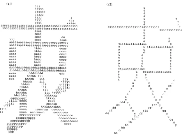
Fig. 11. Stroke pattern “g” to be considered. (a) Label 7 is the upward book, label 3 is the crossing stroke and label 2 is the intermediate stroke; (b)-(e) Several variations of the stroke pattern “K”.
: 8 6 8 9444444444444464 8 9 6 8 9 6 8 9 6 8 9 6 8 9 b 8 9555555555555b5 8 9 a b555555555555585 9 a 9 a 9 a a a a a a a b b b c b c b cc b c b b cc b c dddee bc dd e fffgg dd e ff cl dd e fff Lw dd e ff a fhf *'3 hh T3 hh g hh &I hh hh hh
the affected strokes still had to pass through this par- ticular center point. We used line fitting to construct the skeleton, hence the final result was not a one-pixel, four-connected (or eight-connected) graph.
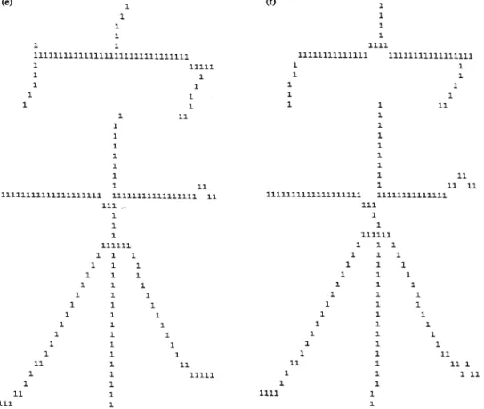
Results for several characters are shown in Fig. 11, 12 and 13. Figure 11 depicts the thinning results of several different variations of the stroke pattern “K”. The connection between the upward hook and the crossing stroke, called an intermediate stroke [see Fig. 1 l(a)], varies as follows [in Fig. 1 l(a)], we do not discuss the strokes labeled 4, 5 and 6 because the characters in Fig. 1 l(b), (c), (d) and (e) have the same structures]: In Fig. 11(b) the two are connected to become a run (labeled “f” in the figure, with no inter- mediate stroke). In Fig. 1 l(c), the top end of the upward hook (labeled 9”) and the bottom end of the crossing stroke (labeled “r”) are connected directly together (no intermediate stroke). In Fig. 11(d), the upward hook and the crossing stroke are separated by a run (labeled “p” which is an intermediate stroke). In Fig. 1 l(e), two runs (labeled “n”; which is an intermediate stroke) lie between the upward hook and the crossing stroke.
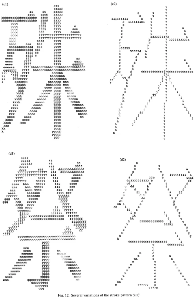
Figure 12 depicts the thinning results for several variations of the stroke pattern “B.“. The “.@” in Fig. 12(a) is the standard character shape. In Fig. 12(b),
the horizontal line on the top of the character (labeled “E” and “F” in the figure) is formed from two horizontal runs, whereas in the second horizontal line a third run appears between the two horizontal runs (labeled “v” and “t”). In Fig. 12(c), there is a horizontal line with two runs (labeled “j”). In the character in Fig. 12(d), the top horizontal line is composed of three runs (labeled “b”) and the bottom horizontal line is com- posed of four runs (labeled “h”).
Even though many different types of connections appear in Figs 11 and 12, acceptable thinning results were obtained for all of the characters shown.
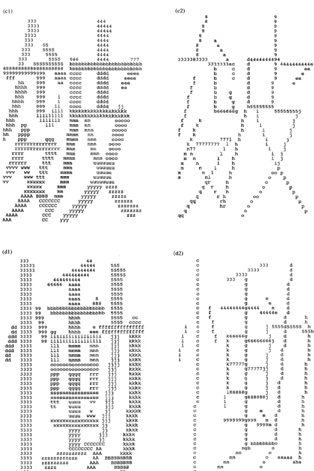
Figure 13 depicts several characters with relatively high stroke counts. A variety of different touching strokes and boundary noise can be seen in these characters. Again, our method achieved reasonably good thinning results for all of the characters shown.
In order to evaluate the thinning results of the pro- posed method, it is compared with four existing algor- ithms.‘g-‘2’ In Figs 14 and 15 we show the thinning results for the five methods. In general, the proposed method produces better results in two respects: strokes at crossing sections are preserved and the resistance to noise at the character border is high.
A Chinese-character thinning algorithm based on global features and contour information 505 (al) 3333 4444 666666666666666 666666666666666 7777 8888 7777 8888 7777 8888 7777 8888 7777 8888 7777 8888 7777 8888 7777 8888 7777 8888 ddddddddddddd ddddddddddddd eeee ffff eeee ffff eeee ffff eeee ffff eeee ffff eeee ffff eeee ffff eeee ffff eeee ffff jjjjjjjjjjjj? ~~~~713113131 mnunm 1111 mmmm 1111 mmmm 1111 mmmm 1111 mmmm 1111 Imnmm 1111 mmmm 1111 mmmm 1111 mmnlm 111 inmnlm 1111 llulum 1111 mnunm 111 mmmm 111 mmun 111 vwvvvyvvw 111 vvvvwvvw 11 vvvvvvV 1 vvvv bbbbbbb c bbbbb cc bbbb ccc bbbb ccc bbbb cccc bbbbb ccccc gggggggggggggggggggggg ggggggggawgggggggggg ggggggggggggggggg ggggggggggg hhhh iiii kkkkkkkkkkkkkkkkkkkkkk kkkkkkkkkkkkkkkkkkkkkk ll"IUl oocm nnnn 0000 nnnn 0000 ~IX-l" 0000 nnnn 0000 PPPPPPPPPPPPPPPPPPPP qqqq rrrr qqqq rrrr (bl) W’) a a b c a b c a d3333 b e44444 a d 3333313 e 4444:c a d b e c a d b e c a d b e c a f d b e c f d 5555555:55 f d b e c b e c a 555f5 d b e c a d8888888 b egg99999 c a d b¶ e ch a d z e h a d e h j d : e h ij d e h i j : g e i e :: i j 9" e h il j ; j g mn kl P g m nnn :: kl 0 PPP g m kl nnq 0 PPr m kl 4 0 r m k 1 q 0 r m k Cl r m k : : 0 r m k 1 0 r m k : : 0 r m 4 0 r m 1 0 r m 1 0 r m 9" 1 0 r m : 0 : 0 r m 4 II m 1 q 1 o" r m r m lo 6666 r m : 1 Cl 7777 q 666r m 1 777q I 33 3333 44 3333 4444 333 7777777777777 333 7777777777777 333 888 9999 333 888 9999 333 888 9999 333 d 888 9999 333 ddd 888 9999 eeeeeeeeeeeeeee 888 9999 eeeeeeeeeeeeee 88888 9999 l-l"ll EEEEEEE 9999 nnn fff EEEEEEEE nnnn fff ggggggg nnnnnn fff j 4499 KKKKKXX fff gggg 00000 ppp fff gggg 000~~ PPPP fff gggg 00000 pppp fff gggg ~mo;; PPPP fff 4949 PP ffff gggg qq rrr GGGGGG qggg qqq rrr qqq rrr lnJu +J&w3~ U"U 94 rrr U"U xxxxxxx qqq === uuu A xXxX qq 3Tr-r uul.l xxxx qqq rrr uuuu xxxx 44 r== uuuu xxxx q rrr lluu xxxx rrr uuu xxxx uuuu xxxx uull xxxx uuu xxxx “UUU xxxx uuu xxxx uull xxxx U”U xxxx Ul” ccccccccc uu ccccccc cccc cc 55 666 5555 aaaaaaaaaaaaaa aaaaaaaaaaaaaa bbb CCC= bbb CCC= bbb CCCC bbb CCC= bbb cccc bbb cccc bbbbb CCC= FFFFFFF CCC= hhh FFFFFFFF hhh iiiiiii hhh 1 iiii hhh iiii hhh iiii hhh iiii hhh iiii hhhh iiii 111111 iiii sss ttt iiii 555 mQ4MMMM sss wwww sss wwww 555 wwww 55 wwww sss wwww ss wwwww ss DDDDDDDDD s DDDDDDD DDDD DD Fig. 12 (Cont.) (a21 c33333 c 3333338 c d c d c d c d c d c d c d c d c d c44444 d c 444dd c d c d c d c d c d c d c d c d c d ic6666 d i 66666d i d i d i i : i i : i d i d i i : i d i i : i d i aaa d i aaaaaad i b b b b b fee b fff b fff b fff gf h h : h h Cl h : :: g555555555555555555h j777777777 1 777777777k ! : k i k 3 k j88888888 k i 8888888kk k 1: k k j99999999 k ] 99999999k k : k k j 1
506 J.-Y. LIN and Z. CHEN (cl) 333 33333 44 55 33333 4444 5555 33333 bbbbbbbbbbbbbbbbbbb 5555 3333 bbbbbbbbbbbbbbbbbbb 5555 3333 cccc 555 3333 (a 7 7 9 7 9 7 9 7 9 7 9 7 9 7 a Y 7 a 9 7 a b333333373 a 8 8 444444444 8 c 444444484 c c c c c c cccc 5555 3333 6 5555 3333 666 555 3333 66666 cccc cccc 77777777777777777777777 cccc 77777777777777777777777 cccc 8888 9999 cccc aaa 888 9999 ddddddddddddd 888 9999 dddddddddddddd 888 9999 eeee ffff 88 9999 eee ffff 8 9999 eeee fff 9999 Lw eeee ffff 9999 gwg eeee ffff 9999 wxKw eeeeee fff hhhhhhhhhhhhhhhhhhhhhhhhhhhhh qqqqqqq ffff hhhhhhhhhhhhhhhhhhhhhhhhhhhh iii jjjj ffff hhhhhh ii jjj ffff hhhhhhhh ii rrrrrrrr hhhhbhhhh i kkkkkkk hbhhhhh ""n kkkkk hhhhhhhh ""n b 7 3333333333a b 7 c c f: 7 c55555 7 c 555558 b 7 c d b 7 c : b 7 c 7 e c d 7 e c d 7 e d 7 e 666666666666j76666666666666e f g j7i f ff whd j 7i f .j 7 i 7 i j' 7 i h i 7 i kkkk 0000 PPPP k!% ~~~~~ PPPP ~0~~~ PPPP kkk 00000 PPPP kkkk 00000 PPPP kkkk 00000 PPPP kkk 00000 PPPP kkkk 00000 PPPP kkkk 0000 PPPP kkk 0000 PPPP kkkk 0000 PPPP kkkk 0000 PPPP E 000 PPPP PPPP kk PPPP k PPPPP PPPPP PPP nnn ““ml nnnn ““““” ““““” nnnnn lUl”ll”” h h h .- 1 7 i jj 7 i i 7 i h 7 h ,j- 7 h 7 h ,j' h h .jj' 7 7 j' 7 7 i 7 i i i i i i i nnnnnn nnnnnn nnnnn nn h 1 .- 7 h hh Cdl) 3333 33333 44 W) 8 8 8 8' 8 33b dc3333333333 b cd c dd bb c d c dd bb c db c de i2i e hh i ee ii e ie ik 333333 44 55 33333 444 5555 3333 666 44 dddddddddddddd 7777777777777777 444 ddddddddddddd 77777777777777777 444 eeeee 7777 9999 444 eeeee 7777777 99999 444 eeee 9 9 a 9 9 444444444 aa 9 44af 9 ff 9 f aaaa bbb 99999 444 eeee aaa bbb 99999 444 eee aaa bbbb 9999 444 eee aaaa sssssss 4444 eee rrrrrr ccccccc tttttt ggg hhh ccccc fffff gw hhh ccccc ffff hhhh cccc ffff hhh cccc ii fffff UUUUUUU iiii fffff jjjjj iiiiii ffffff jjjj kkkkkkkkkkkkkkkkkkk ffffff jjjj kkkkkkkkkkkkkkkkkk fffffff jjjjj ffffffff jjjj fffffff jjjjj 11 ffffff jjjj 1111 ff jjjj 111111 ooooooooooooooooooooooooooooooo 000000000000000D0000oooooooooD DDDD 9 f 9 f 9 ff 9 f Yf ; 4 -4 j j.