國
立
交
通
大
學
電機資訊學院 資訊學程
碩
士
論
文
802.11 無線網路 PCF 協定即時傳輸服務之研究
A Study of Real-Time Transmission Services
Based On PCF Protocol of 802.11 Wireless
Networks
研 究 生:許銘釗
指導教授:陳耀宗 博士
802.11 無線網路 PCF 協定即時傳輸服務之研究
A Study of Real-Time Transmission Services Based On PCF
Protocol of 802.11 Wireless Networks
研 究 生:許銘釗 Student:Ming-Chuan Hsu 指導教授:陳耀宗 Advisor:Yaw-Chung Chen 國 立 交 通 大 學
電機資訊學院 資訊學程
碩 士 論 文 A ThesisSubmitted to Degree Program of Electrical Engineering and Computer Science, College of Electrical Engineering and Computer Science
National Chiao Tung University In partial Fulfillment of the Requirements
For the Degree of Master of Science
in
Computer Science
June 2005
Hsinchu, Taiwan, Republic of China
A Study of Real-Time Transmission Services Based On PCF
Protocol of 802.11 Wireless Networks
Student:Ming-Chuan Hsu Advisor:Yaw-Chung Chen
A Thesis
Submitted to Degree Program of Electrical Engineering and Computer Science,
College of Electrical Engineering and Computer Science National Chiao Tung University
In partial Fulfillment of the Requirements For the Degree of
Master of Science in
Computer Science June 2005
802.11 無線網路 PCF 協定即時傳輸服務之研究 研 究 生:許銘釗 指導教授:陳耀宗 國 立 交 通 大 學電 機 資 訊 學 院 摘要 在未來的無線網路,不同的即時傳輸服務特性將有不一樣的傳輸 要求;如傳輸效率,最大容忍錯誤,延遲時間等等。然而在目前的無
線網路像是 IEEE 802.11 無線區域網路(Wireless LAN)中,並沒有提
供一個標準的方法來滿足這樣的即時傳輸服務特性。
IEEE 802.11 的媒體存取控制(Medium Access Control)提供非同
步及有時間限制的方式在基礎架構(Infrastructure)及隨意架構(Ad
Hoc)模式下來傳輸無線網路資料。其中基本的 IEEE 802.11 無線區域
網 路 的 媒 體 存 取 控 制 方 式 就 是 使 用 分 散 協 調 式 (Distributed
Coordinator Function);它是利用載波感測多重存取及碰撞避免
(Carrie Sense Multiple Access / Collision avoidance)的技術,
及利用 backoff 的模式來傳輸無線網路資料。另一個選擇性的 IEEE
802.11 無 線區域 網路的 媒體存 取控制 是使用 集中協 調式(Point
Coordinator Function);它是使用輪詢的方法為基礎。在集中協調
傳送資料並且避免無線網路下碰撞的發生。因此,不同 IEEE 802.11
的媒體存取控制方法有不同的特性,不論是在傳輸效率或延遲需求也
都需要更進一步來討論及研究。
我們在這篇論文中提出了改善 PCF 輪詢表(polling list)的方
法,來滿足多媒體在無線網路上的即時傳輸特性。首先在 Extended
PCF Polling List Method (EPCF)中,它無條件的重新使用剩餘的免
競爭週期時間(Contention Free Period),來避免原有 PCF 中,浪費
在等待最大免競爭週期(CFPMaxDuration)時間到達。在 Adaptive PCF
Polling List Method (APCF)中,它以 EPCF 為基礎並且考慮到多媒
體在無線網路上的即時傳輸特性。在 APCF 中,我們利用 Association
Request 中的 Capability information field 欄位,讓無線工作站
透過 Beacon Frame 通知 Point Coordinator 提供即時傳輸服務。它
重新安排更適合的輪詢表(polling list)並且減少原本 PCF 中 Point
Coordinator 可能輪詢(poll)到沒有資料要傳送的無線工作站的機
率。最後在 Advanced PCF polling list method (ADPCF)中,它以
APCF 為基礎並且考慮到影音資料在傳輸的特性。在 ADPCF 中,我們
利用影音資料在傳輸時會被切割成多個 Frame 的特性,讓 Point
短影音資料撥放(playback)的延遲時間。這個方法更進一步的改善原
有在 PCF 上支援即時服務的傳輸能力,並且給予使用多媒體的無線工
作站使用者,滿足即時性服務的傳輸要求。為了評估這個方法,我們
將它設計在無線網路存取器(Access Point)中,並透過網路模擬器
(Network Simulator 2)來分析它的傳輸效率,最大容忍錯誤及延遲
時間。在我們模擬結果,使用 Advanced PCF polling list method
(ADPCF)的無線工作站在即時性服務的傳輸,錯誤率及延遲時間上比
原來 DCF 及 PCF 無線工作站較有效率。
關鍵字: 無線網路,即時傳輸服務,媒體存取控制,分散協調式,
載波感測多重存取及碰撞避免,集中協調式,無線網路存取器,網路
A Study of Real-Time Transmission Services Based
On PCF Protocol of 802.11 Wireless Networks
Student:Ming-Chuan Hsu Advisor:Yaw-Chung Chen
Degree Program of Electrical Engineering and Computer Science National Chiao Tung University
ABSTRACT
In future wireless networks, different traffic classes will exhibit a large variety of characteristics and real-time transmission service requirements, such as transmission rate, maximum tolerable error rate and timeout specifications. However, currently there is no standard way of guaranteeing real-time transmission service in wireless access networks like Wireless LAN which is based on IEEE 802.11.
IEEE 802.11 Medium Access Control (MAC) is proposed to support asynchronous and time bounded delivery of radio data packets in infrastructure and ad hoc networks. The basis of the IEEE 802.11 WLAN MAC protocol is Distributed Coordination Function (DCF), which is a Carrier Sense Multiple Access with Collision Avoidance (CSMA/CA) with binary slotted exponential back-off scheme. Another optional IEEE 802.11 WLAN MAC protocol is Point Coordination Function (PCF), which based on a "polling" access method. PCF periodically polls stations and gives them the opportunity to transmit and thus avoids contention for the channel. Since IEEE 802.11 MAC has its own characteristics that are different from other wireless MAC protocols, the performance of reliable transport protocol over 802.11 needs further
study.
In order to provide the real-time services in wireless networks, we propose three methods (1) an extended PCF polling list method. The extended PCF polling list method is used to solve the original PCF which wastes time on waiting for CFPMaxDuration. In this method, we resume the remaining of the contention free period and extend the polling list gratuitously. (2) The adaptive PCF polling list method (APCF) which is based on extended PCF polling list method that consider about a more satisfactory scheme for real-time transmission requirements. In this method, we use a subfield in Association Request management frame of Capability information field to carry the information of transmission requirements on the Beacon frame. (3) An advanced PCF polling list method (ADPCF) which uses a sequence of polling to transmit all of frames which constitutes a picture consecutively. This method is suitable for communications of multi-media streams.
These proposed methods use PCF polling list in an AP that according to transmission rate, maximum tolerable error rate and delay requirements. In order to evaluate the performance, we also introduce an analytical model to compute the throughput, delay, jitter and loss ratio based on NS-2 network simulator.
Keywords: Wireless networks, real-time transmission service,
Medium Access Control, Distributed Coordination Function, Carrier Sense Multiple Access with Collision Avoidance, Point coordination Function, Access Point.
誌 謝 在這兩年研究所的日子,最感謝我的指導教授 陳耀宗老師在這 些研究的過程中不斷的指導及建議,讓這篇論文可以完成。陳耀宗老 師在交大資工所的學術經驗及研究貢獻非常傑出,能夠接受陳老師的 指導,讓學生在這兩年研究所的日子成長很多也收穫很多。實驗室的 學長學弟們,謝謝你們的在這兩年研究所的指教及幫忙,以及一起討 論研究的日子。 我最重要的家人 廣妹 肥肥 糖糖,尤其是廣妹。謝謝你總是在 夜裡無怨無悔的陪伴著我,總是默默地為我釋放壓力,鼓勵我並且為 我照顧這個家,謝謝你。肥肥 糖糖,因為有你們,當我一路走來, 你 們是我精神的支柱,感謝你們,說不完的感謝 。 於 工研院 電通所 2005.7.4 結婚紀念日
Contents
Abstract in Chinese i
Abstract in English iii
Acknowledgements vi
Contents vii
List of Figures viii
List of Table xi
Chapter 1 Introduction...1
Chapter 2 Background and Related Works...3
2.1 Background ...3
2.1.1 Introduction to IEEE standards 802.11...3
2.1.2 MAC Access Time and Interframe spacing...5
2.1.3 Carrier Sensing Function and the Network Allocation Vector...7
2.1.4 Distributed Coordination Function (DCF)...9
2.1.5 Point coordination Function (PCF)...13
2.2 Related Works...20
Chapter 3 Problem Definition...22
3.1 Transmissions Requirement ...22
3.2 CFPMaxDuration limit ...23
3.3 The Problem Analyze and Results ...25
Chapter 4 An Extended PCF Polling List Method ...31
4.1 Proposed Method ...31
4.2 Simulation and Numerical Results...33
Chapter 5 An Adaptive PCF Polling List Method ...41
5.1 Proposed Method ...41
5.2 Simulation and Numerical Results...46
Chapter 6 Advanced PCF Polling List Method ...51
6.1 Proposed Methods...51
6.2 Simulation and Numerical Results...54
Chapter 7 Conclusions...60
Bibliography ...62
List of Figures
Figure 2.1: The family of standards 802.11 relationships ………4
Figure 2.2: The MAC architecture coexistence with DCF and PCF …..4
Figure 2.3: Different interframe space relationships ………...5
Figure 2.4: The relationships between frames and NAV settings. …..8
Figure 2.5: An example of exponential increase of contention window (CW)………..9
Figure 2.6: 802.11 backoff procedure………10
Figure 2.7: The hidden node problem. ……….12
Figure 2.8: RTS/CTS procedure. ………...13
Figure 2.9: Contention free period and content period alternation. ....14
Figure 2.10: Relationship between state variables and services. ……...15
Figure 2.11: Capability information field. ……….16
Figure 2.12: PCF transfer procedure. ………18
Figure 3.1 The simulation model of coexisting DCF and PCF. ……...25
Figure 3.2: The average throughput of DCF and PCF with one mobile station………...26
Figure 3.3: The average delay of DCF and PCF with one mobile station. ………27
Figure 3.4 The average throughput of DCF and PCF with 4 mobile stations. ………..27
Figure 3.5 The average delay of DCF and PCF with 4 mobile stations. ………..……..28
Figure 3.6 The average throughput of DCF and PCF with 8 mobile stations. ………....28
Figure 3.7 The average delay of DCF and PCF with 8 mobile
stations..………29 Figure 3.8: Shorter PCF polling list with large Beacon Intervals….….30 Figure 4.1: An extended PCF polling list. ……….32 Figure 4.2: Relationship with an extended PCF polling list. ……...32 Figure 4.3: The average throughput of DCF and PCF with one mobile
station………...34 Figure 4.4 The average delay of DCF and PCF with one mobile
station. ………...34 Figure 4.5: The average throughput of DCF and PCF with 4 mobile
stations. ………...35 Figure 4.6: The average delay of DCF and PCF with 4 mobile
stations. ………...35 Figure 4.7: The average throughput of DCF and PCF with 8 mobile
stations. ………...36 Figure 4.8: The average delay of DCF and PCF with 8 mobile
stations………..36 Figure 4.9: An example of the CFP interval in excess of
CPFMaxduration. ………37 Figure 4.10: Average throughput of DCF and PCF with 5 mobile stations
and with 8 TU Beacon intervals………...38 Figure 4.11: Average delay of DCF and PCF with 5 mobile stations and
with 8 TU Beacon intervals...………...39 Figure 4.12: Average jitter of DCF and PCF with 5 mobile stations and
with8 TU Beacon intervals. ………..39 Figure 4.13: Average loss ratio of DCF and PCF with 5 mobile stations
and with 8 TU Beacon intervals. ….………..40 Figure 5.1 The new Capability information field. …………..………..42
Figure 5.2 The adaptive PCF polling list Method. …………..………..44 Figure 5.3: An earliest deadline first method. ……….………..45 Figure 5.4 The simulation model of DCF and PCF coexistence
situation with multiple data streams. ………...….47 Figure 5.5: The average throughput of Audio streams under PCF and
APCF. …..………..48 Figure 5.6: The average throughput of Video streams under PCF and
APCF. ………49 Figure 5.7: The average throughput of FTP under PCF and APCF……49 Figure 5.8: The average throughput of Telephony under PCF and
APCF. ……….………...49 Figure 5.9: The average delay of Video, Audio, Telephony and FTP
under PCF and APCF. ………50 Figure 6.1 Example of Advanced PCF Polling List Method
(ADPCF)………..….52 Figure 6.2 Frame transfer example of Advanced PCF Polling List
Method (ADPCF)..………..……….53 Figure 6.3: The simulation model of DCF and PCF coexistence
situation with Video streams. ………….……….55 Figure 6.4: Average throughput of Video streams under Beacon
interval of 100 TUs. ………..……….56 Figure 6.5: Average delay of Video streams under Beacon interval of
100 TUs. ……….57 Figure 6.6: Average jitter of Video streams under Beacon interval
of 100 TUs. ….……….57 Figure 6.7: Average loss ratio of Video streams under Beacon interval
List of Table
2.1 The IFSs time with different physical layer. ……..………6 2.2: CF-Pollable and CF-Poll request in Association Request
management frames. ………..17 3.1: Relationships with different QoS requirements for various
applications. ………..………..23 5.1: Different applications simulation parameters. ………..……..48 6.1: Simulation parameters of different Video streams. ………...……..56
Chapter 1
Introduction
Nowadays, wireless LANs (WLANs) data rate has been increased up to 54 Mbps, thus many multi-media applications are implemented on wireless LAN environment. This has resulted in explosive growth of new media-streaming applications, which lead to extensive research regarding efficient methods to support such applications over today’s wireless LAN. Many applications including audio, video and Internet telephony, have been pushed to deal with delay, loss and time-varying characteristics of best effort wireless networks.
In this thesis, we investigate the IEEE 802.11 MAC layer protocol to deal with the media-streaming characteristic. However, currently there is no standard way of guaranteeing real-time transmission service in IEEE 802.11 WLAN. The MAC protocol for IEEE 802.11 incorporates two access methods. The basic access method is the Distributed Coordination Function (DCF), which is used to support asynchronous data transfer on a best effort basis. The DCF is based on the Carrier Sense Multiple Access with Collision Avoidance (CSMA/CA) protocol. While the contention free service is provided by the PCF, which is based on a “polling” access method. The PCF is implemented as a Point Coordinator (PC), usually at
the Access Point (base station), which periodically polls stations and gives them the opportunity to transmit and thus avoids contention for the channel. When both access methods are used, contention free period (CFP) and contention period (CP) could alternate. Within a CFP repetition interval, a portion of the time is allocated as CFP during which the PCF is active and the remaining time is allocated as CP during which the DCF is active. Recently, real-time transmission service over IEEE 802.11 wireless LANs has been the subject of intensive study in networking literature.
Our study focuses on a near complete polling list solution to IEEE 802.11 WLANs by enhancing the original PCF protocol with better demand assignment features and also by integrating the PCF with a novel polling scheme. A flexible and fair polling list method among the time bounded is provided by this scheme. It is best suited for variable bit rate in real-time applications. Its performance is evaluated using NS-2 network simulator.
The rest of the work is organized as follows. In Chapter 2, we describe the background and related works for media streaming transmission on wireless LAN by using both IEEE 802.11 MAC protocol DCF and PCF mode. In Chapter 3, we outline the problems of original PCF scheme and the real-time applications requirement. In Chapter 4, we propose an extended PCF polling list method (EPCF). An adaptive PCF polling list method (APCF) is presented in Chapter 5. In Chapter 6, we discussed an advanced PCF polling list method (ADPCF), it is suitable for multi-media streaming applications. Finally, Chapter 7 concludes this thesis.
Chapter 2
Background and Related Works
2.1 Background
2.1.1 Introduction to IEEE standards 802.11
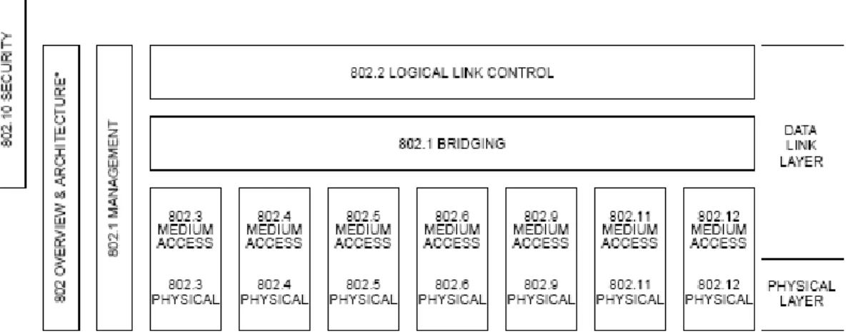
The key of the 802.11 specifications is the MAC. Figure 2.1 shows, the core framing operations and interaction with both wire and wireless networks. Different physical layers can provide different transmission speed, such as 802.11a, 802.11b and 802.11g, all of which are supposed to interoperate.
802.11 uses a carrier sense multiple access (CSMA) scheme to control the access to the transmission medium. However, collisions waste valuable transmission capacity, so rather than the collision detection (CD) employed by Ethernet, 802.11 uses collision avoidance (CA). Also like Ethernet, 802.11 uses a distributed access scheme with no centralized controller. Each 802.11 mobile station uses the same method to access the medium.
Figure 2.1: The family of standards 802.11 relationships.
Access to the wireless medium is controlled by coordination functions, and CSMA/CA is provided by the distributed coordination function (DCF). If contention free service is required, it can be provided by the point coordination function (PCF), which is built on top of DCF and defined as an optional selection on IEEE MAC layer. The PCF are provided only in infrastructure networks. The coordination functions are described in the following section and illustrated in Figure 2.2.The MAC architecture can provide the PCF through the services of the DCF.
2.1.2 MAC Access Time and Interframe spacing
In order to avoid the collisions on 802.11 wireless networks, the interframe spacing plays a role in coordinating the access to the transmission medium. 802.11 uses four different interframe spaces. The relationships between them is shown in Figure 2.3:
Figure 2.3: Different interframe space relationships.
The time interval between frames is called the interframe space (IFS). Some of these interframe space (IFS) are listed in order from the shortest to the longest as follows:
I. SIFS Short interframe space II. PIFS PCF interframe space III. DIFS DCF interframe space IV. EIFS Extended interframe space
The different IFSs are implemented on the wireless mobile stations. Since the collision avoidance is built into the 802.11 MAC, stations must wait a while until the medium becomes idle when a station tries to
transmit a packet. Various interframe spaces create different priority levels for different type of traffic. That is, the higher priority traffic does not have to wait as long after the medium has become idle. Therefore, if there is any higher priority traffic waiting, it grabs the medium access permission before lower priority frames get a chance to transmit.
In order to ensure interoperability between different data rates, the interframe spaces are set to fixed time periods which are independent of the transmission speed.
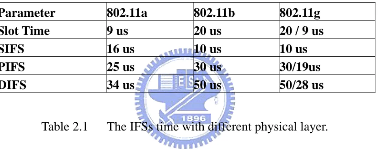
Parameter 802.11a 802.11b 802.11g
Slot Time 9 us 20 us 20 / 9 us
SIFS 16 us 10 us 10 us
PIFS 25 us 30 us 30/19us
DIFS 34 us 50 us 50/28 us
Table 2.1 The IFSs time with different physical layer.
As Table 2.1 shows, different physical layers can specify different interframe space durations. The parameter of SIFS, PIFS and DIFS are presented as follows:
PIFS = Slot Time + SIFS. DIFS = PIFS + Slot Time.
The SIFS is used for the transmission of highest priority traffic, such as clear to send (CTS) / request to send (RTS) frames and positive acknowledgments. Highest priority transmission can begin as soon as the SIFS has elapsed. Once this highest priority transmission begin, the
medium become busy, so frames transmitted after the SIFS has elapsed gain higher priority over frames that can be transmitted only after longer intervals. The PIFS is used by the PCF during contention free operation. Stations with data to transmit in the contention free period can transmit after the PIFS has elapsed and preempt any contention based traffic. The DIFS is the minimum medium idle time for contention based services. Stations may have immediate access to the medium if it has been free for a period longer than the DIFS. The EIFS is used by the DCF whenever the PHY has informed the MAC that a frame was sent and did not result in correct reception of a complete MAC frame which carries incorrect FCS value. It is an interval longer than DIFS which may be required to recover the reception of an error frame.
2.1.3 Carrier Sensing Function and the Network
Allocation Vector
Carrier sensing is used to determine whether the medium is available or not. There are two type of carrier sensing functions in 802.11. The physical carrier sensing function and the virtual carrier sensing function.
Physical carrier sensing function is provided by the physical layer, which is medium dependent. Since it is difficult to implement physical carrier sensing hardware on the media, so another type of carrier sensing function, called virtual carrier sensing is provided by using the Networks Allocation Vector (NAV). 802.11 frames carry a time duration field, which can be used to reserve the medium for a fixed time period. The
NAV is a timer that indicates the amount of the reserved time. The stations set the NAV to the time for which they expect to use the medium, including those frame times to complete the interoperation. Other stations count down from the NAV to zero. If the NAV reaches zero, it indicates that the medium is idle. Otherwise the stations have to wait until NAV becomes zero.
Figure 2.4: The relationships between frames and NAV settings.
Figure 2.4 illustrate the operations of multiple stations with the corresponding timers. The NAV is carried in the frame headers on both RTS and CTS frames. If the NAV is nonzero, stations should wait a while in accessing the medium until virtual carrier sensing indicates the medium become idle. After the transmission completes and NAV count down to zero, the medium can be used by any station after an interframe space (here is DIFS).
2.1.4 Distributed Coordination Function (DCF)
Like Ethernet, in order to avoid the collision, the wireless networks have to checks whether the radio link is clean before transmitting. The DCF is the basis of standard of CSMA/CA mechanism on the 802.11 wireless networks. This access method intents to provide by the collision free service. In the collision free service, the stations use a random backoff scheme before the first frame is transmitted through the radio channel.
Figure 2.5: An example of exponential increase of contention window (CW).
After a frame transmission has been completed and the DIFS has elapsed, stations may attempt to transmit contention based data. Figure
2.5 shows a period called the contention window or backoff window. This window is divided into slots. The slot length is medium dependent that higher speed physical layer uses shorter slot time than lower speed physical layer. Each transmitting station randomly selects a slot and waits until the timer count down to zero. The station with the lowest slot number is the winner.
Figure 2.6: 802.11 backoff procedure.
As Figure 2.6 shows, in DCF, sending stations participate in contention. In this case, a station starts a random backoff procedure, which is the binary exponential backoff, and determines a random number as the slot number, then calculate the backoff time accordingly:
backoff time
=
slotTime*
Random,distributed contention window size as follows:
[0, CW] with CWmin
<
CW<
255Initially CW
=
CWmin is set to 7 in 802.11. If the medium is idle again at least for DIFS, the station decrements the backoff time until the medium gets busy. The station is allowed to send immediately if the random backoff time is decremented to zero.The random backoff procedure has to be started after every transmission. A collision occurs if two (or more) stations have detected the medium as idle for DIFS, both are allowed to send and start their transmissions immediately. To avoid repeated collisions, increasing CWmins is necessary. For the first up to the fourth retransmission the CWmin value is set as follows:
CWmin,new
=
2*CWmin,old + 1 {e.g. 15(1) , 31(2), 63(3), 127(4)}.After five or more retransmissions the CWmin value has to be set to Cwmax
=
255.In some situation, the DCF may use the clear to send (CTS) / request to send (RTS) cleaning technique to further reduce the possibility of collisions. As in Figure 2.7, there is a hidden node problem. The station Z can communication with both station X and Y, but station X and Y can
not communicate with each other directly. Here, the station X and Y are hidden nodes. If stations X and Y transmit simultaneously, both of them would not have any indication regarding the error, because both station X and Y does not hear each other, and the collision occurs at station Z.
Figure 2.7: The hidden node problem.
In order to solving the collision resulted from hidden nodes, 802.11 allows stations to use Request to Send (RTS) and Clear to Send (CTS) signal to clean out the RF area. Both RTS and CTS are control frames by using SIFS interval to notify neighboring mobile stations in the same RF area to avoid collisions.
Figure 2.8: RTS/CTS procedure.
As Figure 2.8 shows, station X has a frame to send, it initiates the process by using a RTS control frame. The RTS frame reserves the channel for transmission, and it causes silence of all stations except the receiver. If the station Z receives an RTS, it immediate responds with an CTS. After the RTS/CTS operation is complete, station X can transmit frames without worrying about the hidden nodes problem. Finally, the station Z receives the frames sent from station X, and immediately responds with an Acknowledgment (ACK) to the sender.
2.1.5 Point coordination Function (PCF)
In order to support real time services, the 802.11 provides contention free services through PCF. The PCF allows the wireless networks to provide a fair scheme to access the medium. This scheme can only be
used in an infrastructure-based network, because it requires an access point (AP). Usually the Point Coordinator (PC) is installed on this AP. The PC manages the access to the medium in the contention free period (CFP) by polling stations sequentially. The polling scheme under the PCF to access medium resembles token based medium access control schemes, and using the AP to handle and operate the token. But the PCF has not been widely implemented on the wireless networks.
The PCF is an optional part of the 802.11 specifications, and contention free service is not always provided during a CFP repetition interval. As Figure 2.9 shows, the contention free service is arbitrated by the point coordinator and alternate with the standard DCF based service. The contention free period repetition interval consists of both contention free period (CFP) and contention period (CP). Alternating periods of contention free service and contention based service repeat at regular intervals, which are the CFP repetition intervals.
In the contention free service, it uses a centralized access control scheme. All stations trying to access the medium are restricted by the point coordinator. At the contention free period, the access point transmits a Beacon frame. The Beacon frame carries the CFPMaxDuration information, which indicates the maximum duration of the contention free period. When a station receives the Beacon, it sets the NAV value to the maximum duration, this restricts the DCF to access wireless medium during the CFP.
Figure 2.10: Relationship between state variables and services.
Figure 11 shows 802.11 state variables, the frame is partitioned into different states and classes. In the initial state 1, the wireless network is neither authenticated nor associated. After a station has successfully authenticated to get into the wireless network, it moves to state 2. At this time, a PCF station sends an Association Request frame for joining the wireless network. Stations enroll in the PCF polling list when they
associate with the access point. The format of the Association Request has a Capability Information field, which is used to indicate the type of network the mobile station wants to join. The Association Request includes a field that indicates whether the station is capable of responding to polls during the contention free period. As Figure 2.11 shows, the Capability Information field can set CF-Pollable and CF-Poll Request subfields in Association Request management frame. The 16 bit Capability Information field is used in Beacon transmissions to advertise the network’s capabilities. In this field, each bit is used as a flag to advertise a particular function of the networks. Stations use the capability advertisement to determine whether they can support or not.
Figure 2.11: Capability information field.
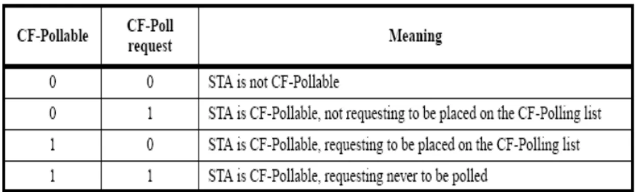
According to Table 2.2, CF-Pollable and CF-Poll Request subfields can indicate the type of networks the station wants to join as well as to request being placed on the contention free polling list. After a PCF station has been successfully associated with the polling list on the point coordinator, the point coordinator polls all associated stations on the polling list for data transmissions during the contention free period.
Table 2.2: CF-Pollable and CF-Poll request in Association Request management frames.
When the PCF is used, time on the medium can be divided into the contention free period (PCF) and the contention period (CF). The contention period must be long enough for the transfer of at least one maximum size frame and its associated acknowledgment. At the beginning of CFP, the point coordinator transmits a Beacon frame which indicates the maximum duration of contention free period (CFPMaxDuration).
As Figure 2.12 shows, all contention free transmissions are separated only by the short interframe space (SIFS) and the PCF interframe space (PIFS). As a result, both SIFS and PIFS are shorter than the DCF interframe space (DIFS). This means that no any DCF based stations can gain access permission to the medium by using the DCF before the expiration of PIFS.
The PCF periodically polls station on its polling list. If no response is received by the point coordinator after a PIFS duration, the point coordinator polls next station on its list. If a polled station has no data to
transmit, it will return a NULL frame to the point coordinator. The point coordinator may also terminate the contention free period by reaching the CFPMaxDuration. The point coordinator transmits a CF-End frame to terminate the contention free period and then the contention period starts.
Figure 2.12: PCF transfer procedure.
In order to increase the transmission efficiency of the contention free period, there are many frame types used within the CF-Pollable stations, these are presented as:
Data
It is used when the access point is sending a frame to the next station and does not need an acknowledgement for previous frame transmission.
CF-ACK
It is used to send acknowledgement when no data needs to be transmitted.
CF-Poll
This is used by the point coordinator to notify the next station that it gains the transmission right, and point coordinator does not have any data for the next station.
Data+CF-ACK
It is used to combine both data transmission and acknowledgement for previous frame transmission.
Data+CF-Poll
This is used to combine both data transmission and notify the next station that it has the transmission right.
CF-ACK+CF-Poll
It is used by point coordinator to combine both acknowledgement for previous frame transmission and notify the next station regarding its transmission right.
Data+CF-ACK+CF-Poll
It is used by the point coordinator for data transmission, acknowledgement and notify the next station that it owns the transmission right.
CF-END
It is used to notify the termination of the contention free period and returns the control of medium to the contention based mechanism of the DCF.
CF-END+CF-ACK
It is used to notify the termination of contention free period and also acknowledgement for previous frame transmission.
In addition to the above frames, we compare PCF with DCF, and we will see which one costs less on the wireless networks transmission. The PCF uses several different frame types and brings together the data transmission, polling feature, and acknowledgement into one frame for maximum efficiency. That is a way to reduce the wireless bandwidth waste during the transmission.
2.2 Related
Works
Performance evaluations of real-time traffic transmission in [3],[4],[7] have shown how the performance varies with the polling scheme and also with the IEEE 802.11 parameter setting using PCF. Other approach in [6], a distributed control algorithm, named as virtual source (VS) algorithm, is designed to extend the DCF to provide service differentiation by continuously keeping track of the health of the channel. From all these studies, the original IEEE 802.11 MAC protocol does not appear satisfactory in providing the real-time transmission service requirements. Most of the work on real-time transmission service requirements over IEEE 802.11 are focused on analyzing the performance of real-time transmission over original IEEE 802.11 WLANs, tuning of parameters such as the value of CFP repetition interval [4] to achieve better performance, or introducing some priority queuing scheme such as varying the back-off value [8] to the original MAC protocol.
Some novel schemes are proved to be effective to provide QoS guarantees over WLANs, such as the blackburst scheme[5]; however, they are not totally compatible to IEEE 802.11 and may impose extra requirements on high priority stations, such as constant access intervals. Also, at higher loads, low priority traffic under those schemes normally suffers from starvation. The new access mechanism called Enhanced DCF (EDCF) [9] developed by the IEEE 802.11e task group is an enhancement of the access mechanisms of IEEE 802.11 for service
differentiation. EDCF combines two measures to provide differentiation. The minimum contention window (CWmin) of the back-off mechanism can be set differently for different priority classes, yielding higher priority to classes with smaller CWmin. For further differentiation, different interframe spaces can be used by different traffic classes. The EDCF could be combined with the PCF features to be the Hybrid Coordination Function (HCF) to simplify the QoS conformance model. The HCF is a coordination function on top of the EDCF to provide contention free and controlled contention transfers during both CP and CFP. The EDCF mechanism is an improvement over the original PCF. However, it suffers from a high rate of collisions. It could give low average delay to high priority traffic, unfortunately, the distribution of delays is however such that at high loads, a rather large fraction of the packets experience very long delays, which might render them useless to real-time applications. At higher loads, low priority traffic also suffers from starvation just like using Blackburst. In many cases it is not desirable to starve low priority traffic, but rather to give a relative differentiation.
Chapter 3
Problem Definition
3.1 Transmissions
Requirement
In this chapter, our study focuses on a more efficient PCF scheme for IEEE 802.11 wireless LAN. In order to support applications that require real-time service, we examine transmission requirements for different applications. As Table 3.1 shows, different applications have various QoS requirements, such as reliability, delay, jitter, bandwidth, and frame transmission period. They are dependent of TCP or UDP transmission schemes.
In the TCP transmissions, usually the stations do not require the time bound delivery of radio data packets in wireless networks, such as E-Mail, File Transfer and Web Access. The station that uses TCP schemes usually concern about the data transmission reliability rather than delay. While the UDP transmission is usually for real-time services, such as Audio, Video, and Telephony applications. The station that uses the UDP schemes, usually do not require very strict reliability in data transmission.
Table 3.1: Relationships with different QoS requirements for various applications.
Different type of real time services have different time bound delivery requirements. These real time services may not be satisfied using PCF scheme by using an enforced fair access to the medium. In some ways, access to the medium under PCF resembles token based medium access control scheme, with the point coordinator holding the token. In this aspect, the PCF has to be some modified according to different real time services.
3.2 CFPMaxDuration
limit
One of the transmission issue to implement the PCF mode to support real time services is the Beacon. Beacon frames are an important part of
network maintenance tasks. They are transmitted at regular intervals to allow stations to detect and identify a network. When a point coordinator transmits a beacon frame to announce the maximum duration of the contention free period (CFPMaxDuration) which is presented as follows:
CFPMaxDuration
=
( BeaconPeriod×
DTIMPeriod×
CFPRate)-
[MaxMPDUTime+
2 SIFSTime+
2SlotTime
+
8 ACKSize].Where the BeaconPeriod is the length of the beacon interval, the DTIMPeriod is the number of beacon intervals between delivery traffic indication map (DTIM) transmissions, the CFPRate is the number of DTIM intervals between contention free periods, the MaxMPDUTime is the time to transmit the maximum size MAC frame.
The station receives the beacon and sets the NAV to maximum duration to lock out DCF based access to the wireless medium. The beacon interval is a 16 bits field set to the number of time units (TU) between beacon transmissions. One time unit is 1024 microsecond. It is common for the beacon interval to be set to 100 TUs, that is about 100 milliseconds. The problem is that the real time applications will have no enough time to support the data transmissions period by using the 100 TUs beacon interval, because the real time applications such as Video, Audio, and Telephony require transmissions periods much shorter than 100 milliseconds (100 TUs).
3.3
The Problem Analysis and Results
In this section, based on previous discussing, the beacon interval may be reduced the required time units according to specific real time applications. Since the beacon interval reduces the number of time units, both contention free period (CFP) and contention period (CP) are curtailed simultaneously. In order to analyze the results of reducing the number of time units, we use the NS-2 networks simulator to evaluate the various beacon interval durations based on the coexistence of PCF and DCF.
Figure 3.1 The simulation model of coexisting DCF and PCF.
Figure 3.1 shows our simulation model, an access point (AP) is used for relaying the packets between wired and wireless network by using the 802.11 MAC scheme. In this model, all of mobile stations are separated by PCF and DCF. They can transmit the packets by using the contention free period and contention period. All of mobile stations are connected to
the access point directly with no longer than 54 Mbps transmission rate. Each mobile station uses bi-directional UDP traffic between itself and access point (AP). The parameters of wireless networks are based on 802.11a, and the access point directly connects to wired network based on by using 100 Mbps transmission rates.
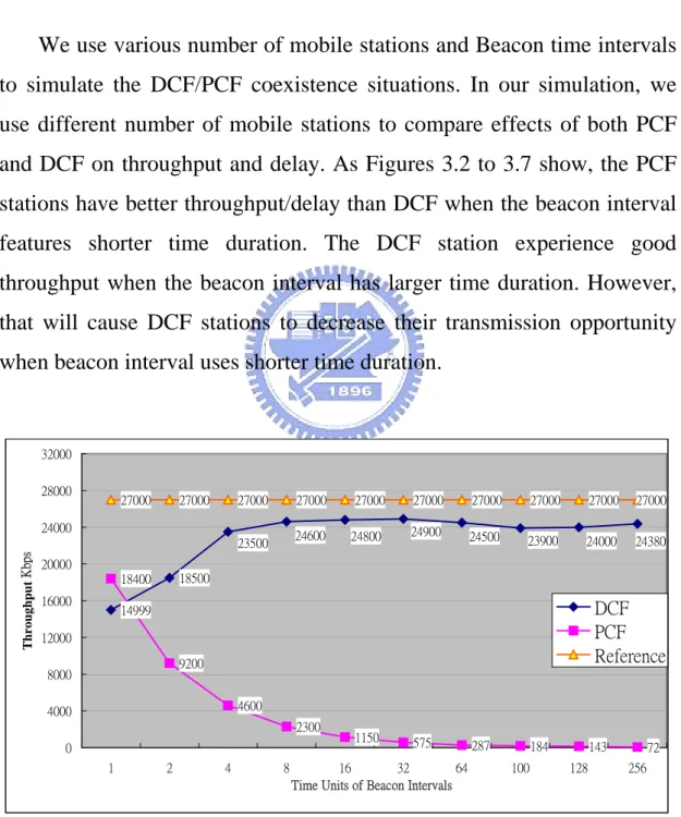
We use various number of mobile stations and Beacon time intervals to simulate the DCF/PCF coexistence situations. In our simulation, we use different number of mobile stations to compare effects of both PCF and DCF on throughput and delay. As Figures 3.2 to 3.7 show, the PCF stations have better throughput/delay than DCF when the beacon interval features shorter time duration. The DCF station experience good throughput when the beacon interval has larger time duration. However, that will cause DCF stations to decrease their transmission opportunity when beacon interval uses shorter time duration.
14999 18500 18400 9200 4600 2300 1150 575 287 184 143 72 27000 27000 27000 27000 27000 27000 27000 27000 27000 27000 24380 23500 24600 24800 24900 24500 23900 24000 0 4000 8000 12000 16000 20000 24000 28000 32000 1 2 4 8 16 32 64 100 128 256
Time Units of Beacon Intervals
T h roughput Kbps DCF PCF Reference
Figure 3.2: The average throughput of DCF and PCF with one mobile station.
0.7 0.7 63.1 99.5 129.2 255.5 1.2 0.74 0.7 0.7 0.7 0.7 0.7 0.7 0.93 1.87 3.7 7.9 16.3 31.4 0 30 60 90 120 150 180 210 240 270 300 1 2 4 8 16 32 64 100 128 256
Time Units of Beacon Intervals
Delay (msec)
DCF PCF
Figure 3.3: The average delay of DCF and PCF with one mobile station.
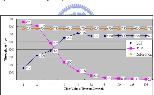
1550 3200 3830 5520 6120 5750 5750 5820 5800 5800 7570 7070 4800 2300 1150 575 287 184 143 72 6750 6750 6750 6750 6750 6750 6750 6750 6750 6750 0 1000 2000 3000 4000 5000 6000 7000 8000 1 2 4 8 16 32 64 100 128 256
Time Units of Beacon Intervals
T h roughput Kbps DCF PCF Reference
Figure 3.4 The average throughput of DCF and PCF with 4 mobile stations.
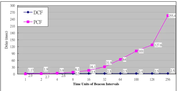
2.5 64 101 127.6 255.4 2.9 2.7 2.6 2.5 2.5 2.5 2.5 2.5 2.5 1.17 1.9 3.9 8.1 16.1 31.9 0 30 60 90 120 150 180 210 240 270 300 1 2 4 8 16 32 64 100 128 256
Time Units of Beacon Intervals
Delay (msec)
DCF PCF
Figure 3.5 The average delay of DCF and PCF with 4 mobile stations.
501 1001 1801 4390 4200 1150 575 287 184 143 72 3375 3375 3375 3375 3375 3375 3375 3375 3375 3375 2001 2801 2960 2940 3040 2940 3040 3600 2200 0 500 1000 1500 2000 2500 3000 3500 4000 4500 5000 1 2 4 8 16 32 64 100 128 256
Time Units of Beacon Intervals
T h roughput Kbps DCF PCF Reference
Figure 3.6 The average throughput of DCF and PCF with 8 mobile stations.
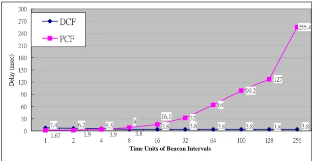
32 64 99.2 127 255.4 3.8 5.5 6.2 7.4 3.8 3.8 3.8 3.8 3.8 3.8 1.67 1.9 3.9 8 16.1 0 30 60 90 120 150 180 210 240 270 300 1 2 4 8 16 32 64 100 128 256
Time Units of Beacon Intervals
Delay (msec)
DCF PCF
Figure 3.7 The average delay of DCF and PCF with 8 mobile stations.
According to these results, we find that both PCF and DCF mobile stations have good throughput when the beacon interval are short for PCF but large for DCF. By comparing different results in Figures 3.2 to 3.7, the PCF mobile stations could be used with large time intervals if the number increases, but the delay of PCF mobile stations still depends on the beacon intervals. Although the DCF mobile stations could use large beacon time intervals no matter the number of mobile stations increases or not, the stations will experience poor throughput and delay when beacon intervals become short.
The PCF problem is that if the number of PCF stations decrease, the throughput of PCF will be degraded when the number of time units of beacon interval becomes larger.
Figure 3.8: Shorter PCF polling list with large Beacon Intervals.
If there is a small number of PCF mobile stations on the PCF polling list, so that it is wasting time on waiting for the contention free period to reach its maximum duration (CFPMaxDuration). As Figure 3.8 shows, the PCF transmission time is much shorter than CFP interval. This is because the CFP interval is dependent on the maximum duration of the contention free period (CFPMaxDuration). When there are few PCF stations on point coordinator polling list, the PCF interval duration will be short. So most of the PCF time is wasted on waiting for CFPMaxDuration to expire, that will cause the throughput of PCF mobile stations to degrade.
Another real time transmission problem is that if the beacon interval increases, the delay of PCF mobile stations also increases simultaneously. This is because each contention free period begins with a beacon frame that contains a DTIM element. Unfortunately, the Beacon intervals are usually too long to support the real time transmission requirements, and it is difficult to use the PCF on time-bounded delivery.
Chapter 4
An Extended PCF Polling List Method
4.1 Proposed
Method
Based on the problem addressed on previous chapters, in order to alleviating the time wasted on waiting for CFPMaxDuration arrival. There are two solutions which can be used (1) to terminate the contention free period immediately when each PCF mobile station is being polled even if the CFPMaxDuration has not been expired yet, (2) to resume the remaining contention free period until the CFPMaxDuration elapsed.
The solution that terminates the contention free period may not fulfill the real-time transmission requirements. Since the problem of delay still appears on contention free periods for beacon intervals with large number of time units. Another problem is, even if point coordinator issues a termination signal to notify the contention free period to terminate, the stations receiving the beacon which contains a termination information then reset the NAV to the new maximum duration and re-computes the contention period, this may not be an efficient way to be used in wireless networks, because if the DCF stations are during power conservation periods they may miss the termination signal. Besides, it needs more
complex algorithm which needs more resources from both point coordinator and mobile stations.
In this section, we propose an extended PCF polling list method to reduce the time wasted on waiting for CFPMaxDuration. In this method, we resume the remaining time of the contention free period and extend the polling list gratuitously. In Figures 4.1and 4.2 shown bellow, we have filled up the CFP duration by replicating the PCF polling list. As a result, the CFP duration might not waste much time on waiting for CFPMaxDuration to expire.
Figure 4.1: An extended PCF polling list.
The algorithm of the extended PCF polling list is presented as follows:
If ( CFP_ Duration
<
CFPMaxDuration) {If ( lastPolled == Null || lastPolled == lastElement ) { ToBePolled = firstElement;
} else {
ToBePolled = lastPolled->next; }
}
4.2
Simulation and Numerical Results
We have implemented the extended PCF polling list method as part of the NS-2 networks simulation with modification to the original PCF wireless model, as well as conducted initial simulation studies to evaluate its performance and delay characteristics relating to 802.11a. As part of our studies, we focus on two metrics: (1) the throughput improvement achieved through the extended polling list method, (2) the potential reduction of AP to mobile delay resulted from resuming the remaining CFP intervals.
The parameters of the NS-2 simulator are tuned to the model as shown in Figure 3.1 with 54 Mbps data rates. All DCF data packets of mobile stations are preceded by an RTS/CTS exchange regardless of the size. To measure the throughput, high packet rate sources were run over UDP. The packet rate at the source was kept high enough to ensure availability of queued packets at any point in the simulation. The
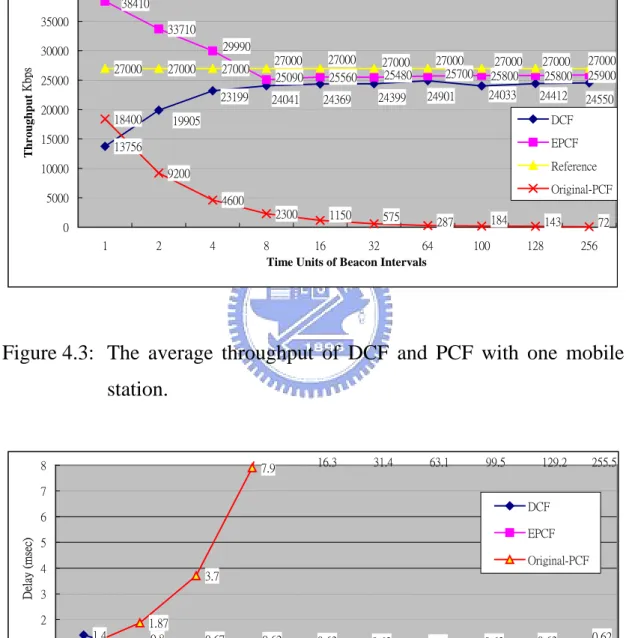
throughput was measured by counting the number of received packets at the access point (AP). We measured delay only for packets that were received at the access point (AP). Note that the maximum packet size of 2312 Bytes is assumed. 13756 33710 25560 25800 25800 25900 27000 27000 27000 19905 23199 24041 24369 24399 24901 24033 24412 24550 38410 29990 25700 25090 25480 27000 27000 27000 27000 27000 27000 27000 18400 9200 4600 2300 1150 575 287 184 143 72 0 5000 10000 15000 20000 25000 30000 35000 1 2 4 8 16 32 64 100 128 256
Time Units of Beacon Intervals
T h roughput Kbps DCF EPCF Reference Original-PCF
Figure 4.3: The average throughput of DCF and PCF with one mobile station. 1.4 0.32 0.35 0.8 0.67 0.62 0.62 0.62 0.62 0.62 0.62 0.62 0.59 0.49 0.42 0.52 0.52 0.54 0.54 0.56 0.93 1.87 3.7 7.9 16.3 31.4 63.1 99.5 129.2 255.5 0 1 2 3 4 5 6 7 8 1 2 4 8 16 32 64 100 128 256
Time Units of Beacon Intervals
Delay (msec)
DCF EPCF Original-PCF
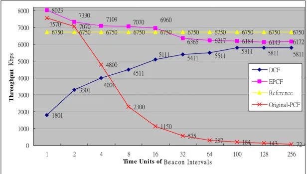
1801 3301 8023 6217 6184 6143 6172 6750 67507070 6750 6750 6750 6750 6750 6750 6750 6750 4800 2300 1150 575 287 184 143 72 4001 4511 5111 5411 5511 5811 5811 5811 6960 7109 7330 7070 6365 7570 0 1000 2000 3000 4000 5000 6000 7000 8000 1 2 4 8 16 32 64 100 128 256
Time Units of B e a c on Int e rva l s
Throughput Kbps DCF EPCF Reference Original-PCF
Figure 4.5: The average throughput of DCF and PCF with 4 mobile stations. 3.8 2.4 2.7 2.7 2.7 2.7 1.4 2.1 2.2 2.1 2.4 2.3 2.3 2.1 2.3 8.1 16.1 31.9 64 101 127.6 255.4 4 2.9 2.8 2.7 1.1 1.17 3.9 1.9 1 2 3 4 5 6 7 8 1 2 4 8 16 32 64 100 128 256
Time Units of Beacon Intervals
Delay (msec)
DCF EPCF Original-PCF
441 801 1618 3184 3143 3172 3375 3375 3375 3375 3375 3375 3375 3375 1150 575 287 184 143 72 2044 2701 2840 2840 2840 2960 2988 3492 3540 3207 4423 4163 3950 3640 3375 3375 2200 4390 4200 3600 0 1000 2000 3000 4000 1 2 4 8 16 32 64 100 128 256
Ti me Uni t s of Be acon Inte rvals
Throughput Kbps DCF EPCF Reference Original-PCF
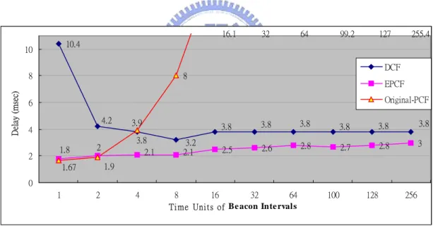
Figure 4.7: The average throughput of DCF and PCF with 8 mobile stations. 10.4 2.5 2.6 2.8 2.7 2.8 3 8 16.1 32 64 99.2 127 255.4 3.2 3.8 4.2 3.8 3.8 3.8 3.8 3.8 3.8 1.8 2 2.1 2.1 1.67 1.9 3.9 0 2 4 6 8 10 1 2 4 8 16 32 64 100 128 256
Ti me Uni t s of Be acon Inte rvals
Delay (m sec) DCF EPCF Original-PCF
Figure 4.8: The average delay of DCF and PCF with 8 mobile stations.
Figures 4.3 to 4.8 show, the performance and delay results under the topology of coexisting DCF and PCF. While the throughput improvement of extended PCF polling list method are always higher than that of DCF mobile stations. The delay improvements are quite significant that
comparing with the original PCF scheme. Note that the delay also includes the buffering delay at source stations.
In Figure 4.3 to 4.8, the efficiency of PCF mobile stations are always higher than DCF stations. This is because that the PCF mobile stations do not require RTS/CTS to precede data packets, and the PIFS length is also less than DIFS. Further, the PCF periodically polls station on its polling list, even if the number of mobile stations increases. Since the DCF uses a random backoff scheme before the first frames is transmitted to the radio channel, the contention based scheme wastes much time on waiting for contention window counting down to zero, regardless the number of mobile stations. In our simulation, we present a “reference” curve to help us compare the effect of the real performance. That is, if there are 8 mobile stations on the simulation model by using 54 Mbps data rates, they are expected to achieve a maximum of 6.75 Mbps raw data rates.
Figure 4.9: An example of the CFP interval in excess of CPFMaxduration.
We also studied the behavior of extended PCF polling list method during a short duration of the beacon interval. As Figure 4.9 shows, the point coordinator may terminate any CFP at the CFPMaxDuration, based on available traffic and size of the polling list. The contention period may be delayed due to a transmission in contention free period. Because, if the CFP interval does not reach the CFPMaxDuration, the point coordinator still has time to perform a poll to the next station. If the transmission time including the acknowledgment packet is in excess of the CFPMaxDuration interval, the contention period interval will be delayed for a time duration required to complete the current PCF frame exchange.
In this case, we studied the effect of packet transmission times for different packet sizes on extended PCF polling list method. We use various packet lengths to simulate various scenarios.
4800 4900 5000 4900 4800 4700 4500 4300 4100 4000 4800 4900 5000 5240 5530 5630 5800 6000 6100 6300 5400 5400 5400 5400 5400 5400 5400 5400 5400 5400 4000 4500 5000 5500 6000 6500 50 100 150 200 250 300 500 700 1000 1500
Packet Size (Bytes)
Throughput Kbps
DCF PCF Reference
Figure 4.10: Average throughput of DCF and PCF with 5 mobile stations and with 8 TU Beacon intervals.
2.447 2.44 2.47 2.486 2.508 2.531 2.575 2.631 2.715 2.38 2.4 2.391 2.385 2.419 2.414 2.425 2.447 2.447 2.458 2.927 2 2.1 2.2 2.3 2.4 2.5 2.6 2.7 2.8 2.9 3 50 100 150 200 250 300 500 700 1000 1500
Packet Size (Bytes)
Delay (msec)
DCF PCF
Figure 4.11: Average delay of DCF and PCF with 5 mobile stations and with 8 TU Beacon intervals.
2.56 2.89 2.96 3.03 3.37 3.77 4 4.44 4.91 6 2.15 2.29 2.29 2.32 2.46 2.52 2.52 2.73 2.89 3 0 1 2 3 4 5 6 7 50 100 150 200 250 300 500 700 1000 1500
Packet S ize (Bytes)
Jitter (msec)
DCF PCF
Figure 4.12: Average jitter of DCF and PCF with 5 mobile stations and with 8 TU Beacon intervals.
0.02 0.027 0.02 0.02 0.032 0.027 0.055 0.06 0.05 0.077 0.078 0.114 0.118 0.14 0.154 0.187 0.244 0.325 0.426 0.544 0 0.1 0.2 0.3 0.4 0.5 0.6 50 100 150 200 250 300 500 700 1000 1500
Packet Size (Bytes)
Loss Ratio
DCF PCF
Figure 4.13: Average loss ratio of DCF and PCF with 5 mobile stations and with 8 TU Beacon intervals.
In our simulation, as shown in Figures 4.10 to 4.13, we use various packet sizes to simulate the short beacon intervals. In these results, the throughput of PCF mobile stations increases when packet size increases simultaneously. But the delay, jitter, and loss ratio are degraded in this case. The DCF mobile stations were deeply significantly by varying packet sizes.
Chapter 5
An Adaptive PCF Polling List Method
5.1 Proposed
Method
As described in the previous chapters, the PCF scheme uses an enforced fair access to the medium. Different applications have various transmission periods. When the number of mobile stations grow up, this is not a good method by using the fair scheme for real-time applications. The point coordinator may poll a station without transmission requirement during the CFP. It will waste the bandwidth of wireless channels. This is because a point coordinator does not have enough information to determine which station needs be polled. As a consequence, PCF scheme is not satisfactory to provide the real-time transmission services.
Other approaches use priority queuing scheme to fulfill the wireless QoS requirements in wireless networks. The new access mechanism Enhanced DCF (EDCF) is an enhancement of the access mechanisms of IEEE 802.11 for service differentiation. For constant access intervals, the mobile stations with high load, low priority traffic under those schemes
normally suffer from starvation. According to our study, the constant traffic priority queue is not suitable to apply on various real-time transmission intervals.
Figure 5.1 The new Capability information field.
At the beginning, we proposed an adaptive PCF polling list method (APCF) that intents to provide a better scheme for real-time transmissions.
First, we modified the subfields in Association Request management frame of Capability information field to carry the information of transmission requirements on the beacon frame. As Figure 5.1 shows, the original subfield in Capability field of B5 to B15 are designed for reservation only. In our proposed scheme, we use these reserved bits as a so-called CF MaxTransmission Interval field. The field of CF MaxTransmission Interval is used to indicate the transmission requirements of mobile stations when they want to join the PCF polling list by using the Association Request management frame. The CF MaxTransmission Interval is an information field with the length 11 bits. The bit of B15 is least significant bit, and the bit B5 is the most significant bit, respectively of time values. The bits from B5 to B15 represent the transmission intervals at the mobile stations. For example, if the mobile stations require 20 millisecond for transmission services, they
may use the bits from B5 to B15 to represent the value as follows:
B5 B6 B7 B8 B9 B10 B11 B12 B13 B14 B15 0 0 0 0 0 0 1 0 1 0 0
The field of CF MaxTransmission Interval is an 11-bits field set to the number of time bound (TB). One time bound unit is one millisecond. The maximum time bound unit of this field is 2048 milliseconds. In this case, 00000010100 represent 20 milliseconds. In order to being compatible with original Association Request management frame of Capability information field, the field of CF MaxTransmission Interval set all bits to zero that indicates the mobile stations does not require time bound service any more.
Based on the aforementioned field, the point coordinator can re-compute the new polling timing during the contention free period. As Figure 5.2 shows, the point coordinator holds a timer for each successful associated mobile station. Each mobile station has a special timer length bounded by the field of CF MaxTransmission Interval on the point coordinator. The point coordinator has to record the time elapsed during contention free period. If the time are elapsed for a while, the point coordinator will mark the timer of each station as time used. When the timer of the mobile station reaches CF MaxTransmission Interval, the point coordinator will give it the opportunity to transmit. Otherwise, the mobile station has to wait until the time of CF MaxTransmission Interval expired.
polling list method, it fills up the CFP duration by replicating the PCF polling list. The major difference between the adaptive PCF polling list method (APCF) and the extended PCF polling list method (EPCF) is the polling scheme during contention free period. In the former, polling the next station is depending on the transmission opportunity of mobile stations by the bounded time.
Figure 5.2 The adaptive PCF polling list Method (APCF).
When more than one mobile station obtain the transmission opportunity, the point coordinator has to judge which one is with highest
opportunity to transmit. In this case, we proposed an earliest deadline first (EDF) scheme for the point coordinator. As Figure 5.3 shows, the point coordinator for each mobile station with a bounded timer, the station A and B got the transmission opportunity simultaneously in this case. The time duration left by station A is tA, while is the time to reach for next CF
MaxTransmission Interval deadline. Similarly, the time duration left by station B is tB, which is the duration for station B to reach its CF
MaxTransmission Interval deadline. In our EDF scheme, we will judge and decide that the mobile station B should be polled first, because tB is
shorter than tA.
Figure 5.3: An earliest deadline first method.
In this thesis, we do not care about the time is excess of CF MaxTransmission Interval, even if the mobile station spends time duration longer than CF MaxTransmission Interval. The reason is, if the
mobile station has a shorter CF MaxTransmission Interval, it is always with highest opportunity to transmit than that with the larger one. So, in this way, low time bound traffic under this scheme normally won’t suffer from starvation.
On the other hand, if there is no real-time mobile station that reaches the CF MaxTransmission Interval, the normally transmitting mobile stations which do not require any time bound will use the time left to access the medium during the contention free period. As in our proposed scheme, the contention free period is separated into real-time and non real-time periods. The real-time period has higher priority than non real-time period. That means, when a mobile station that gets the transmission opportunity, the point coordinator polls this mobile station first, the scenario repeats until all of mobile stations that got the transmission opportunity have been polled. Otherwise, the point coordinator polls the non real-time mobile station during the contention free period.
5.2
Simulation and numerical Results
In order to analyze the behavior of different real-time applications for various transmission intervals by using the adaptive PCF polling list method (APCF), we use the NS-2 to simulate various traffic intervals based on coexisted PCF and DCF.
to Figure 3.1 that uses the same parameters on both wireless and wired networks. In this model, the point coordinator holds a timer for each successful associated mobile station from the field of CF MaxTransmission Interval. While the data stations do not require any time-bounded services in this model.
Figure 5.4 The simulation model of DCF and PCF coexistence situation with multiple data streams.
Each PCF mobile station has different application type used in the content free period (CFP). As shown in Table 5.1, we gave each PCF mobile station various transmission intervals and service requirements according to the characteristics of real-time applications.
Table 5.1: Different applications simulation parameters.
The time-bound (TB) was set on the subfields in Association Request management frame of Capability information field to carry the information of transmission requirements in the Beacon frame. For example, the Video is set to 4 TB, the Audio is set to 3 TB, the Telephony is set to 25 TB, and the File Transfer is set to 0 TB. The mobile stations of DCF are using normal TCP data transfer and packet size is set to 1500 Bytes.
1440 1440 1440 1440 1440 1343 1195 1043 925 833 1440 1440 1440 1440 1440 1440 1440 1440 1380 1240 500 1000 1500 2000 4 8 12 16 20 24 28 32 36 40
Number of mobile stations
T h roughput Kbps PCF-Audio APCF-Audio
Figure 5.5: The average throughput of Audio streams under PCF and APCF.
3110 3110 3110 2430 1810 1330 1204 1030 977 812 3110 3110 3110 3110 3110 2710 2100 1700 1376 1271 0 1000 2000 3000 4 8 12 16 20 24 28 32 36 40
Number of mobile stations
T h roughput Kbps PCF-Video APCF-Video
Figure 5.6: The average throughput of Video streams under PCF and APCF. 18700 7950 4140 18700 7950 4140 1850 350 270 190 2450 1877 1394 1224 1064 998 886 600 550 120 0 2000 4000 6000 8000 4 8 12 16 20 24 28 32 36 40
Number of mobile stations
T h roughput Kbps PCF-FTP APCF-FTP
Figure 5.7: The average throughput of FTP under PCF and APCF.
64 64 64 64 64 64 64 63.2 63.2 63.2 64 64 64 64 64 64 64 64 64 64 63 63.5 64 64.5 65 4 8 12 16 20 24 28 32 36 40
Number of mobile stations
T h roughput Kbps PCF-Telephony APCF-Telephony
0 4 8 12 16 20 24 4 8 12 16 20 24 28 32 36 40
Number of mobile stations
Delay (msec) PCF-Audio PCF-Viedo PCF-Telephony PCF-FTP APCF-Audio APCF-Video APCF-Telephony APCF-FTP
Figure 5.9: The average delay of Video, Audio, Telephony and FTP under PCF and APCF.
As Figure 5.5 to 5.9 show, we use multiple applications in the simulation to evaluate both throughput and delay. The types of PCF mobile stations are categorized into Audio, Video, Telephony and File Transfer, which are coexisting during contention free period. In order to simulate different types of real-time applications, which are mixed for the comparison of both extended PCF polling list method (EPCF) and adaptive PCF polling list method (APCF). The adaptive PCF mobile stations are flagged by APCF while EPCF mobile stations are not flagged. In the simulation results, the throughput of APCF is higher than EPCF, this is because the bandwidth in APCF does not waste on polling a station without data during the contention free period. Further, the APCF stations can provide more precise timing in data transmission by using APCF. So, the throughput of APCF mobile stations can be kept at highest level even the number of mobile stations increases.
Chapter 6
An Advanced PCF Polling List Method
6.1 Proposed
Method
In this chapter, we improve the adaptive PCF polling list method, called Advanced PCF Polling List Method (ADPCF), this is similar to the adaptive PCF polling list method (APCF), however the major different between this method (ADPCF) and the APCF is the structure of the polling list. In the ADPCF, we use a sequence of polling list to transmit the real-time data to mobile stations. This is because some multi-media pictures are consisted of many frames. So, if we divide a picture into many fragments which are transmitted in a non-consecutive way, it may cause increase of delay time and may waste the time on waiting for fragments to re-assembly a picture at the receiver.
To avoid the fragmentation delay, the point coordinator has to transmit fragments of a picture all at once. As Figure 6.1 shows, the point coordinator repeats and polls the same mobile station until all MAC frames on the packet buffer have been transmitted. The transmission opportunity also depend on setting in the field of CF MaxTransmission
Interval.
Figure 6.1 Example of Advanced PCF Polling List Method (ADPCF).
Same as APCF, if no real-time mobile stations reaches CF MaxTransmission Interval, that means there is no any real-time transmissions happened, the mobile stations that do not need real-time services will use the remaining period to access the medium. As Figure 6.1 shows, suppose that the mobile station D use normal data transmission that does not require any time-bound from the field of CF MaxTransmission Interval, under such situation, the mobile station D can transmit data when there is no real-time mobile station reaching the bound of CF MaxTransmission Interval.