6 3 = -(1/0.31)e4
+
(40/0.31)u (23)e4 = (1/0.33)e3 (24)
Again, U =
-&
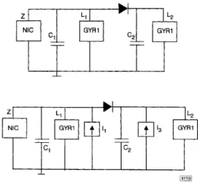
k,e, represents a state feedback. The diagram of the synchronisation scheme is given in Fig. 3, where the black boxes with I, = -4o(s(x) - s(y)) and I, = (40/0.3l)(s(x) - s(y)) rep-resent the coupling between the oscillators. Since the controllabil- ity matrix [11] of the system of eqns. 21 - 24 is full rank, the
eigenvalues can be placed, for instance, in -1 for k , = -0.0109, k2
= 0.0178, k3 = 0.0319, k4 = 4.0046, synchronising the systems of eqns. 13 - 16 and eqns. 17 ~ 20. Fig. 4 shows that yl(t) tracks x,(t)
after the synchronising signal is switched on at (t/T) = 30, with T
= dL,C,, x1 = U;, No, y , = U;l /Uo, U, = 0.65V (see [9]).
m Fig. 3 Oscillators with gyrators: synchronisation scheme
3 2
5 1
X 1 -2 -3 0 40 60 80 100 trrFig. 4 Time waveforms of chaotic variables x l ( t ) and y l ( t ) ofsystems in eqns. 13 - 16 and eqns. 17 - 20, respectively
Here, T = 0.237ms, xI = Vil /Uo, y l = U;, /Uo, U, = 0.65V
It is worth noting that the error systems of eqns. 9 ~ 12 and
eqns. 21 - 24 have been globally asymptotically stabilised at the
origin. Therefore, it is not necessary for the initial conditions of the corresponding drive and response systems to belong to the same basin of attraction.
Conclusions: In this Letter a new tool for synchronising two exam-’ ples of hyperchaotic oscillators using a scalar transmitted signal has been proposed. The idea is to design the synchronising signal so that a linear time-invariant error system is obtained. In this way, synchronisation can be achieved by exploiting results from modern control theory. The approach is simple, rigorous and does not require the computation of any Lyapunov exponent [7]. 0 IEE 1998
Electronics Letters Online No: 19980099
G. Grassi (Dipartimento di Matematica, Universita di Lecce, 73100 Lecce, Italy)
2 February 1998
S. Mascolo (Dipartimento di Elettrotecnica ed Elettronica, Politecnico di Bari, Via Orabona 4, 70125 Bari, Italy)
E-mail: mascolo@poliba.it S. Mascolo: Corresponding author References
1 CARROLL, T.L., and PECORA, L M.: ‘Synchronizing chaotic circuits’, ZEEE Trans., 1991, CAS-38, (4), pp. 453456
2 TAMASEVICIUS, A.: ‘Reproducible analogue circuit for chaotic synchronisation’, Electron. Lett., 1997, 33, (13), pp. 1105-1106 3 NAMAJUNAS, A., and TAMASEVICIUS, A.: ‘Simple RC chaotic
oscillator ’, Electron. Lett., 1996, 32, (ll), pp. 945-946
4 TAMASEVICIUS, A., MYKOLAITIS, G., and NAMAJUNAS, A.: ‘Double scroll in a simple 2D chaotic oscillator’, Electron. Lett., 1996, 32, CUOMO, K.M., OPPENHEIM, A.v., and STROGATZ, s.H.: ‘Synchronisation of Lorenz-based chaotic circuits with applications to communications’, IEEE Trans., 1993, CAS-40, (lo), pp. 626-633 6 TAMASEVICIUS, A., CENYS, A., and MYKOLAITIS, G.: ‘Driving
nonlinear resonator with hyperchaotic signals’, Electron. Lett., 1996,32, (22), pp. 2029-2030
7 TAMASEVICIUS, A., MYKOLAITIS, G., CENYS, A., and NAMAJUNAS, A.: ‘Synchronisation of 4D hyperchaotic oscillators’, Electron. Lett., 8 TAMASEVICIUS, A., NAMAJUNAS, A., and CENYS, A.: ‘Simple 4D
chaotic oscillator’, Electron. Lett., 1996, 32, (1 l), pp. 957-958 9 TAMASEVICIUS, A., CENYS, A., MYKOLAITIS, G., NAMAJUNAS, A., and
LINDBERG, E.: ‘Hyperchaotic oscillators with gyrators’, Electron. Lett., 1997, 33, (7), pp. 542-544
10 BROGAN, w.L.: ‘Modern control theory’ (Prentice-Hall, New Jersey, 1991)
11 CHEN, c. T.: ‘Linear system theory and design’ (Holt, Rinehart and Winston, 1984)
12 CHUA, L.o., DESOER, c.A., and KUH, E.S.: ‘Linear and nonlinear circuits’ (McGraw- Hill, New York, 1987)
(14), pp. 1250-1251 5
1996, 32, (17), pp. 1536-1538
Adaptive receiver for DS/CDMA
communications over impulsive noise
channels
Ho-Chi Hwang and Che-Ho Wei
A new adaptive algorithm is proposed for training soft-limiter based correlation receiver in which the direct sequence code division multiple access signals corrupted by impulsive symmetric a-stable noise are demodulated. The new adaptation algorithm allows simpler implementation and faster convergence speed in comparison with the traditional adaptive stochastic gadient- based algorithms.
Introduction: Adaptive linear filtering algorithms have been com- monly used to train minimum mean-squared error (MMSE) linear detectors [ 11 for demodulating direct-sequence code division multi- ple access @S/CDMA) signals over an additive white Gaussian noise (AWGN) channel. However, in some realistic communica- tion links, some natural, as well as man-made, interference is non- Gaussian and impulsive [2]. The impulsive noise is commonly rep- resented by the symmetric a-stable (SaS) process [2], in which the probability density function (pdf) is given by fa(y,
6;
x) = (U24:
exp(jhylola)eJ~xdco, where a(0 < a I 2) implies the ‘thick- ness’ of the tails of the pdf and the dispersion1.(r
> 0) relates to the spread measure of the pdf around the location parameter, 6. When the SaS process has a smaller a, it has a largely increased probability of large amplitudes.Because SaS noise (except a = 2) has no finite variance, the least mean p-norm (LMP) algorithm [2] and the normalised LMP algorithm [3] instead of the least-mean-square (LMS) error algo- rithm are used for adaptive linear filtering for S d random proo esses. The value of p , constrained to p < a , is usually taken a s p = 1 when a is either unknown or varying in time. Whenp = 1, the LMP algorithm is called the least mean absolute deviation (LMAD) algorithm. In this Letter, a new adaptation algorithm is developed for adjusting the soft-limiter (SL) correlation receiver for demodulating the DSiCDMA signals corrupted by SaS noise.
SL correlation receiver: In an equivalent K-user DS/CDMA com- munication system, the received signal vector of one symbol inter- val can be expressed by
K
r ( j ) = b k [ j ] A k U k f X ( j ) (1) k = l
where b,[il is the transmitted symbol, A, is the received amplitude and U, E RNxl is the signal vector of the kth user and
xG]
is theSaS noise vector. Assuming that the first user is desired, the SL correlation receiver maps the weigkted sum of
rb]
and produces the test statistic of b,[il as follows: b ,[il = gSL(wTh] rfi]), where wfj) is the tap-weight vector and gsL(x) is the soft limiter, the output of which is equal to +1, -1, orx
asx
t 1x
5 -1, or1
x
1
< 1, respec- tively.Since the error signal, efj) = b,[il -
61[il,
is no longer S& dis-tributed, the LMP algorithm can be used to adjust wb] by mini- mising c@)(j] = Ie(j)p. The updating equation can be expressed as
w ( j
+
1) = w ( j ) +~sgn(e(j))le(j)I”-lgsL(WT(j)r(j)).(j) (2) where p is the step size and g’sL(x) = dgsL(x)/dx. For the SL corre- lation receiver, p is not limited to be <a.
The use of 1 < p < 2, as suggested by [4], can provide the capability of robust error sup- pression in eqn. 2.Novel adaptation algorithm: Utilising the properties of limiting output and binary transmission we define the following hkelihood cost function inspired by [5]:
1 f b b1
=
E
(2 - (1+
b l [ j ] ) + ( l - &[j])V} = E{
1 - sgn(bl [j1)61U]}
( 3 )The stochastic gradient-based adaptation algorithm, termed the likelihood cost algorithm (LC algorithm), can be expressed as
w ( j
+
1) = w(A + Clsgn(bl[jl)g~L(wT(j)r(J))r(j) (4) From eqn. 4, we see that the LC algorithm gains some advan- tages over the LMP algorithm for training the SL correlation receiver:(i) The term, le(j)p-l, is dropped off such that the LC algorithm has a simpler computation for weight adaptation.
(ii) The effective step size for the LMP algorithm can be written as
pLMp(f] = plb,G] -
6,(j]1p-’
in comparison with the LC algorithm.Assuming that
6,fj)
is uniformly distributed within [-1, +1] and that the decision error occurs with probability P(e) [4], the average step size, pLMP,aV, can be obtained asWhen
P(e)
approaches zero, the average step sizepLMp,av
becomes approximately (l/p)p, while the effective step size for the LC algo- rithm is always equal to p. Thus, the LC adaptation algorithm can increase the convergence rate with low computational complexity in comparison with the LMP algorithm for p # 1. Actually, the LC algorithm and the LMP algorithm with p = I (i.e. LMAD algo- rithm) adjust the weights following the direction of the gradient descent of the same instantaneous error. The LC algorithm, how- ever, is easier to implement because the calculation of eb] is not necessary.Simulation result: Consider an DS/CDMA communication system with
K
= 5 users. Each interfering user has 10 times as much power as the desired user. The ratio between signal power, A,*,and SaS noise dispersion, y, is 5dB. The transient behaviour of the SL correlation receiver, using the LC adaptation algorithm (SLI
LC), is investigated in comparison with those of other receivers using different adaptation algorithms: the linear detector with the LMAD algorithm (linear/LMAD), the single layer perceptron (SLP) correlation receiver [6] with the LMAD algorithm (SLP/ LMAD), and the SL correlation receiver with the LMAD algo- rithm (SWLMAD). The tap-weight vectors of these receivers after every 10 iterations are used to calculate the probability of errone- ous detection by the Fourier-Bessel series approximation [7] in each run.
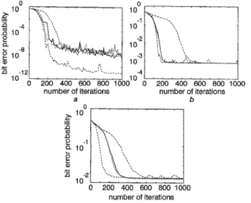
Fig. 1 shows the average bit error probability of several receiver schemes against the training sequence length by ensemble averag-
ing over 100 simulation runs. When the ambient noise is Gaussian (i.e.
a
= 2.0), the 1inearLMAD scheme converges slowly, while the SLP/LMAD scheme has the fastest convergence speed and the best BER performance. The SLLMAD scheme and the SLiLC scheme can achieve compatible steady-state BER performance rel- ative to the linearLMAD scheme. As the ambient noise becomes impulsive (i.e.a
= 1.9 ora
= 1.5), the 1inearLMAD scheme con- verges slowly compared to the Gaussian noise case while the SLP/ LMAD scheme always converges robustly. The SLiLMAD receiver and SLLC scheme have almost the same convergence characteristic, having a fast convergence speed compared to the linear/LMAD scheme.0
10
-4
d o
0 200 400 600 800 1000 number of iterations number of iterationsa b b IO0
7
n 10 e 0 200 400 600 800 1000 number of iterations CFig. 1 Transient behaviour of several correlation-type receivers in M A 1 and symmetric a-stable noise channels
a
a
= 2.0 (Gaussian) . . . SLiLMAD ba
= 1.9 (Gaussian) . . . SLiLMAD 1ineariLMAD 1ineariLMAD SLPiLMAD - - - - SLPiLMAD SLPiLC SLPiLC _ _ _ _ ca
= 1.5 (Gaussian) _ _ - - SLPiLMAD . . . SLiLMAD 1ineariLMAD SLPiLCConclusion: A new adaptation algorithm has been developed for the SL correlation receiver to adaptively demodulate DSiCDMA signals corrupted by S d noise. The SLLL scheme has a slower convergence speed than the SLPiLMAD scheme, but implementa- tion of the SWLL scheme is easier. Alternatively the SLiLL scheme with very low complexity has a faster convergence speed than the linearLMAD scheme.
0 IEE 1998
Electronics Letters Online No: 19980350
Ho-Chi Hwang and Che-Ho Wei (Depurtment of Electronics Engineering and Center f or Telecommunications Research, National Chiao-Tung University, Hsin-Chu, Taiwan 30050, Republic of China) E-mail: chwei@cc.cntu.edu.tw
Che Ho Wei: Corresponding author
14 November 1997
References
1 MILLER, s.L.: ‘An adaptive direct-sequence code-division multiple- access receiver for multiuser interference rejection’, IEEE Trans. Commun., 1995,43, pp. 1746-1755
2 NIKIAS, C.L., and SHAO, M.: ‘Signal processing with alpha-stable distributions and applications’ (New York, 1995)
3 ARIKAN, o., CETIN, A.E., and ERZIN, F.: ‘Adaptive filtering for non- gaussian stable processes’, IEEE Signal Process. Lett., 1994, 1, pp, 163-165
4 SIU, s., CHANG, c.H., and WEI, c.H.: ‘L, n o m back propagation algorithm for adaptive equalization’, IEEE Trans. Circuits Syst. 11, 1995, 42, pp. 604607
5 SHANG, c., HOLT, M.J.J., and COWAN, C.F.N.: ‘Log-likelihood adaptive algorithm in single-layer perceptron based channel equalisation’, Electron. Lett., 1995, 31, pp. 1900-1902
6 MITRA, U,, and POOR, H.v.: ‘Adaptive receiver algorithms for near- far resistant CDMA’, IEEE Truns. Commun., 1995, 43, pp. 1713- 1724
HWANG, H.c., and WEI, c.H.: ‘Performance of linear detectors for DSiCDMA in impulsive noise channel’. Proc. IEEE PIMRC, Taiwan, 1996, pp. 560-564
7
Adaptive space-time reduced-length
MMSE
receiver for interference suppression in
DS/CDMA
V.D. Pham
and
T.B.
Vu
The authors present an adaptive space-time reduced-length minimum mean-squared error (MMSE) receiver to suppress co- channel interference in the near-far environment for an asynchronous direct-sequence code-division multiple-access (DS/ CDMA) system. Simulation results show that better bit-error rate and faster and more stable convergence are achieved over the existing full- and reduced-length MMSE receivers.
Introduction: In DSICDMA, full-length MMSE receivers [l, 21 only use the desired spreading code and need no information about other users. However, one practical limitation is that the number of adaptive taps must be equal to the code length. This approach to interference suppression may be difficult to imple- ment in a system with large processing gain, and the performance may be degraded by significant coefficient noise and slow conver- gence due to a large number of adaptive taps. Several modifica- tions have been proposed [l, 31 to reduce the length of the adaptive filter. The analytical results in [4] show that the full- length MMSE receiver performs significantly better than the cycli- cally shifted filter bank (CSFB) MMSE receiver with fewer taps (reduced length) [l] at the expense of an impractically long train- ing period for large processing gain. The reduced- length MMSE receiver converges faster at the expense of high bit-error rate (BER), and small processing gain also degrades the performance of this receiver.
The use of antenna arrays and spatial processing has been shown to increase system capacity [5, 61. From the viewpoint of improving the performance of the existing reduced-length MMSE receiver, a modified configuration is proposed for use with an adaptive array antenna, which adaptively updates its weights by using reliable reference signals obtained from the reduced-length MMSE receiver, to take advantage of both space and time processing.
m Fig. 1 Adaptive space-time reduced-length MMSE receiver
System description: In an asynchronous DSICDMA system, the received signal due to the kth user is expressed as
00
T k ( t ) =
4%
b k ( t ) a k ( f-
ZT-
T A ) COS(Ld,f+
0,)z = - m
k = 1 , 2 ,
...,
k (1) wheree,,
b,(i), andPk
are the phase, ith bit (Tl), and received power, respectively, of the kth user. T i s the bit period of the kth user, andw,
is the carrier frequency. T, is the delay of the kth user, defined as T/< = p,T,+
S,, where p , is an integer, T,(=TlN) is theELECTRONICS LETTERS
5th March
1998Vol.
34chip period and 0 5
6,
< T,. The spreading waveform a,(t) of the kth user is assumed to be of polar form with rectangular pulse, and periodic with period T. The spreading code vector a, of the kth user is defined as a, = ( u ~ , ~ , ak,l,...,
ak,N-l)T, where N is the period of the spreading sequence.Fig. 1 shows a block diagram of the adaptive space-time reduced-length MMSE receiver, which has an adaptive array antenna with M elements followed by an adaptive CSFB filter. After converting the signal to baseband, the received continuous time signal at each antenna element is discretised by sampling, at the chip rate, the output of the chip matched filter. Considering the demodulation of the 0th bit b,(O) of the 1st user, the total received sample signal vector r, at the mth antenna element is rep- resented by
k = l
x exp(j(m - 1)(27rd/X) sin & )
+
n, (2) wherefk(n) = (0,0,
...,
Q,O,...,
a k , , - d Tg k ( n ) =
(a,%,
Q , n f l , - - - 1 U k , N - l , 0,0,..-,
oIT
( 3 4
( 3 4
n, is a zero-mean Gaussian random vector in the mth element. d,
h, and @, are the element spacing, free-space wavelength, and arrival angle of the kth user, respectively. The array output is expressed as
M
y ( n ) = 1 w m ( n ) r m ( n ) n = i N , i N + l ,
...,
i N + N - I m = l(4) Using the least mean-squared (LMS) algorithm, the successive updating of the complex weight of the mth antenna element at time n is given by
w,(n
+
1) = w,(n) - Plel(n)Y(n)* ( 5 )where
*
denotes the complex conjugate, p1 is the step size, ande,@) is the error signal. The array output vector at the ith data sampling time is input to a bank of
D
filters(D
<N)
which are cyclically shifted versions of the matched filter for the desired sig- nal. Successive shifts are spaced by A = NID. Each filter output is sampled once every symbol interval, and theD
samples so obtained are combined according to an MMSE criterion. The lth filter is specified byhl(n) = a l [ ( n + l A ) mod NI 0
5
n5
N-1,05
15
D-1 (6) Defining z(l) = hlTy, the D-tap coefficient vector c is updated as follows:c ( i
+
1) = c ( i ) - pZez(i)z* ( 7 )where
b,
and e,(i) are the step size, and error signal, respectively. Simulation results: Bit- and chip-asynchronism as well as code acquisition for a desired user are assumed in the simulation. The desired and interference sequences are selected from Gold sequences with code length N = 31, and the number of taps in the adaptive CSFB filter is D = 10. The number of antenna elements is 2, and the element spacing is one-half wavelength. There are one desired and two interference signals with directions of arrival (DOA’s) of 45, 0, and -45” with respect to broad side, respec- tively. Both interferers are received at lOdB stronger than the desired signal. During training, complex weights and tap coeffi- cients are updated by using known training signals, and then by demodulated data when the error has been reduced to a tolerable level. Step sizes are lo”, and le2 for the space domain, and time domain, respectively.In Fig. 2, with the desired signal received at an EJN0 of 5dB, a faster and more stable convergence with lower steady-state MSE value is obtained for the proposed adaptive space-time reduced- length MMSE receiver in comparison with the existing full-length