dc spin current generation in a Rashba-type quantum channel
L. Y. Wang,1C. S. Tang,2 and C. S. Chu11Department of Electrophysics, National Chiao Tung University, Hsinchu 30010, Taiwan 2Physics Division, National Center for Theoretical Sciences, P.O. Box 2-131, Hsinchu 30013, Taiwan
共Received 15 August 2005; revised manuscript received 2 November 2005; published 2 February 2006兲 We propose and demonstrate theoretically that resonant inelastic scattering共RIS兲 can play an important role in dc spin current generation. The RIS makes it possible to generate dc spin current via a simple gate configuration: a single finger gate that locates atop and orients transversely to a quantum channel in the presence of Rashba spin-orbit interaction. The ac-biased finger gate gives rise to a time variation in the Rashba coupling parameter, which causes spin-resolved RIS and, subsequently, contributes to the dc spin current. The spin current depends on both the static and the dynamic parts in the Rashba coupling parameter,␣0and␣1, respectively, and is proportional to␣0␣1
2
. The proposed gate configuration has the added advantage that no dc charge current is generated. Our study also shows that the spin current generation can be enhanced significantly in a double finger-gate configuration.
DOI:10.1103/PhysRevB.73.085304 PACS number共s兲: 73.23.⫺b, 72.25.⫺b, 72.30.⫹q
I. INTRODUCTION
Spintronics is important in both application and funda-mental arenas.1,2 A recent key issue of great interest is the
generation of dc spin current 共SC兲 without charge current. Various dc SC generation schemes have been proposed, in-volving static magnetic field,3–5 ferromagnetic material,6 or
ac magnetic field.7More recently, Rashba-type sporbit
in-teraction 共SOI兲 in two dimension electron gas 共2DEG兲8–10 has inspired attractive proposals for nonmagnetic dc SC generation.11–13Of these recent proposals, including a time-modulated quantum dot with a static spin-orbit coupling,11
and time modulations of a barrier and the spin-orbit coupling parameter in two spatially separated regions,12 the working
principle is basically adiabatic quantum pumping. Hence, si-multaneous generation of both dc spin and charge current is the norm. The condition of zero dc charge current, however, is met only for some judicious choices for the values of the system parameters.
It is known, on the other hand, that quantum transport in a narrow channel exhibits resonant inelastic scattering 共RIS兲 features when it is acted upon by a spatially localized time-modulated potential.14,15This RIS is coherent inelastic
scat-tering, but with resonance at work, when the traversing elec-trons can make transitions to their subband threshold by emitting mប⍀.14,15Should this RIS become spin resolved in
a Rashba-type quantum channel共RQC兲, of which its Rashba coupling parameter is time modulated locally, we will have a simpler route to the nonmagnetic generation of dc SC. Thus, we opt to study, in this work, the RIS features in a RQC. This requires us to go beyond the adiabatic regime and into the regime when either or n⬃ប⍀. We solve the
time-dependent spin-orbit scattering 共SOS兲 for all possible inci-dent electron energies and obtain large RIS contribution. In the adiabatic regime, however, with,nⰇប⍀, we find that
the dc spin-pumping effect from a sole SOI time-modulated region is small.12
II. SYSTEM CONFIGURATION
The system configuration considered is based on a RQC that forms out of a 2DEG in an asymmetric quantum well
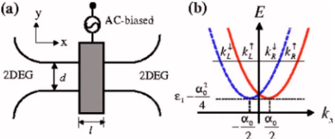
by the split-gate technique. As is depicted in Fig. 1共a兲, a finger gate 共FG兲 is positioned above while separated from the RQC by an insulating layer. A local time variation in the Rashba coupling parameter ␣共r,t兲 can be induced by ac biasing the FG.12,13 The Hamiltonian is given by H=p2/ 2m +H
so共r,t兲+Vc共y兲 where the Rashba term Hso共r,t兲 = M ·
1
2关␣共r,t兲p + p␣共r,t兲兴. 共1兲
Here, M = zˆ⫻, zˆ is normal to the 2DEG,is the vector of Pauli spin matrices, and Vc共y兲 is the confinement potential.
The unperturbed Rashba coupling parameter ␣共r,t兲 is ␣0
throughout the RQC, but becomes␣0+␣1cos⍀t in the
re-gion underneath the ac-biased FG. The Dresselhaus term is neglected for the case of a narrow-gap semiconductor system.16
To demonstrate the pumping mechanism, we consider a narrow RQC in which its subband energy spacing is much greater than the Rashba-induced subband mixing. As such, the unperturbed Hamiltonian, in its dimensionless form, is
H0= −ⵜ2+␣0y共i/x兲+Vc共y兲. Appropriate units have been
used such that all physical quantities presented here, and henceforth, are dimensionless.15In particular,␣is in unit of vF*/ 2, and spin in unit ofប/2. The right-going 共R兲 eigenstate of H0, in the nth subband, is n共y兲n共x兲, where
n共x兲=exp关ikn,R x兴. The wave vector kn,R =
冑
n+␣0/ 2,FIG. 1.共Color online兲 共a兲 Top-view schematic illustration of the RQC. The ac-biased FG, of width l, is indicated by the gray area; 共b兲 the electron dispersion relation of an unperturbed RQC.
while = ± 1 denotes the eigenvalue of to the operator
y. n is the energy measured from the nth subband
threshold such that the energy of the eigentstate is
E =n+n−␣20/ 4, forn=共n/ d兲2. This dispersion relation is
shown in Fig. 1共b兲. The subband withn⬃ប⍀ is found to
contribute most to the RIS-enhanced spin pumping. It is of import to note that right-going electrons have兩kR↑兩 ⬎兩kR↓兩 and
that, at the subband threshold, kR↑共↓兲= kL↑共↓兲.
III. PHYSICAL PICTURE
In this section, we show that the physical origin of the dc SC generation can be understood from two perspectives. A weak pumping regime result is then obtained for an explicit confirmation of our physical reasoning.
The first perspective is associated with the vector poten-tial. In the ac-biased region,H=Hx+Hy, the transverse part Hy= −2/y2+ Vc共y兲, and the longitudinal part
Hx共t兲 =
冉
− i x+ ␣共x,t兲 2 M · xˆ冊
2 −1 4␣共x,t兲 2. 共2兲The form of Eq.共2兲 suggests an effective vector potential, A共t兲=21␣共x,t兲M·xˆ, which depends on the spin and gives rise to a spin-resolved driving electric field E = −A /t. However,
inHx, the A2term does not depend on, while for the term
linear in A, A= −12␣共x,t兲 gives rise only to a trivial spin dependence, which can be easily removed by a shift in the origin of time for the case of an oscillatory␣共x,t兲. Yet it turns out that the full term linear in A, given by −i共/x兲xˆ·A,
manages to give rise to nontrivial spin-resolved transmis-sions. In a perturbative sense, this term becomes kR↑共↓兲Ax, for
the case of a right-going electron incident upon a spatially uniform␣共t兲. This renders the effective longitudinal driving field to become spin dependent, through the factor kR↑共↓兲. The difference in the current transmissions, for up and spin-down cases, is proportional to the difference in kR↑共↓兲, or␣0,
and is found to be amplified by RIS. This breaking of the longitudinal symmetry in the effective driving field by ␣0 leads to the generation of dc spin current in a FG-RQC struc-ture that has but an apparent longitudinal configuration sym-metry, and with zero source-drain bias. No dc charge current will be generated, however, in such a structure.
An alternate perspective for the understanding of the ori-gin of the spin-resolved current transmission is associated with a unitary transformation. By introducing a unitary trans-formation ⌿共x,t兲=exp关共i/ 2兲兰−l/2x ␣共x
⬘
, t兲dx⬘
兴共x,t兲, the Schrödinger equation关Eq. 共2兲兴 becomes冋
− 2 x2+ U1共t兲 + U2 共t兲册
共x,t兲 = i t共x,t兲, 共3兲of which the two time-dependent potentials are U1共t兲 = −␣共x,t兲2/ 4 and U2共t兲=共⍀␣1/ 2兲共x+l/2兲cos共⍀t+/ 2兲.
Even though only U2depends on spin, both the term in U1共t兲
that oscillates with frequency⍀ and U2together constitute a pair of quantum pumping potential that pump SC. This is our major finding in this work: that spin pumping nature is built-in even in a single FG configuration.
The SC expression for a state ⌿ is given by the SC density operator Jˆx y = i
冋
⌿ † x y⌿− H.c.册
+ ␣ 2⌿ †兵 y,M其x⌿. 共4兲The SC conservation is maintained by the supression of sub-band mixing and the associated spin-flipping in a RQC. For a scattering state⌿, the SC can be expressed in terms of the transmission coefficients. More specifically, the ratio be-tween the time-averaged transmitted and the incident SC gives the spin-resolved current transmission T␣ , where␣,, are, respectively, the incident and the transmitting lead. Sum-ming over contributions from all states in reservoirs R and L, the SC is
Is= I↑− I↓, where
I=
冕
dEf共E兲关TRL − TLR 兴, 共5兲and I is the number current due to electrons with spin from both reservoirs that are under zero source-drain bias condition. Here TRL =兺n兺m共
n m⬎0兲T
n,RL
m, and f共E兲 is the
Fermi-Dirac distribution. The transmission coefficient Tn,RLm, =兩tn,RLm,兩2
冑
n m
/n denotes the current transmission that an
electron incident from terminal L in the spin channel , subband n, energy E, is scattered into terminal R, sideband
m, with kinetic energy n
m
=n+ m⍀. The net charge
current is given by Iq= I↑+ I↓. In a symmetric FG
configura-tion, we have TLR = TRL−, so that the net spin current is Is= 2兰dEf共E兲共T
RL ↑ − T
RL
↓ 兲 and the net charge current is
identi-cally zero.
In the weak pumping共WP兲 regime, when␣1is small, we
can demonstrate analytically, and most unequivocally, that spin-dependent reflection arises merely from the aforemen-tioned linear A term in Hx共t兲. We outline the derivation here
while leaving the detail in Appendix A. Tracing up to the first order in␣1, our derivation retains the reflection
ampli-tudes to m = ± 1 sideband and drops that to the m = 0 side-band. Contribution to the total reflection includes thus reflec-tion at either the left or the right edges of the time-modulated region. For an electron incident from terminal L with wave vector kn,R 共E兲, the reflection at the left edge is obtained from the wave-function continuous condition and the boundary condition − x兩⌿兩x=共− l/2兲++ x兩⌿兩x=共− l/2兲− + i 2␣1cos⍀t兩⌿兩x=−l/2= 0. 共6兲 In the time-modulated region, the wave function ⌿ consists of one-sideband terms, given by the form
eikn,R 共E±⍀兲xe−i共E±⍀兲t, and the m = 0 term, given by the form eikn,R 共E兲xe−iEt关1+
/共2⍀兲␣1kn,R 共E兲共ei⍀t− e−i⍀t兲兴. The extra ⍀t
dependence in the m = 0 term is resulted from the time-dependent driving effect of A, which is obviated by the
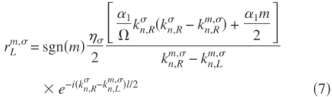
weighting factor that involves␣1kn,R . The reflection ampli-tude rLm, at the left edge is obtained to be
rL m,= sgn共m兲 2
冋
␣1 ⍀kn,R 共kn,R − kn,Rm,兲 + ␣1m 2册
kn,Rm,− kn,Lm, ⫻ e−i共kn,R −kn,L m,兲l/2 共7兲 for m = ± 1. The first term in the numerator of Eq. 共7兲 is clearly due to A, because of the factor␣1kn,R , and the secondterm is due to the scattering at the edge. Here the wave vector kn,Rm,共L兲= ±共n
m兲1/2+
␣0/ 2, with upper 共lower兲 sign
corresponds to the right-共left-兲 moving electron in the nth subband, mth sideband, and with kinetic energy n
m
. It is clear then that wave-vector differences in both the numerator and the denominator of rL
m,are spin independent. Hence, the
spin dependence arises solely from the␣1kn,R factor in the first term of the numerator in Eq.共7兲, or from A. This con-firms our understanding of the physical origin of the dc SC generation.
Including the reflection at the right edge, we obtain the total reflection amplitude
rn,LLm, =关1 − ei共kn,R −kn,L m,兲l
兴rLm,. 共8兲
We note that the spin dependence of this total reflection amplitude is associated with ␣0. In fact, it turns out that
the SC is proportional to ␣0. The SC is related to the current transmission, which, within the aforementioned approximation, is given by TRL ⬇1−兺n关Rn,LL1, + Rn,LL−1,兴, where Rn,LLm,=兩rn,LLm,兩2
冑
n m
/
冑
n. From Eq.共5兲, the energy derivativeof the zero-temperature SC is given by Is/E = 2⌬TRL
= 2共TRL↑ − TRL↓ 兲 from which its explicit expression is given by
Is E= 1 2␣0␣1 2
兺
n m=±1兺
共n m⬎0兲 兵1 − cos关共冑
n+冑
n m兲l兴其冋
冉
1 4冊
2 −冉
1 ⍀共n−冑
nn m兲 +m 4冊
2册
n冑
n m . 共9兲That this expression diverges whenn m
= 0, for m⬍0, exhib-its the RIS feature unambiguously and also demonstrates the need to go beyond the one-sideband approximation near the RIS condition.
IV. NUMERICAL RESULTS AND DISCUSSIONS
In the following, we present results obtained from solving the time-dependent SOS exactly, in the numerical sense. An outline of the method is presented in Appendix B. Physical parameters are chosen to be consistent with the InGaAs-InAlAs–based narrow-gap heterostructures such that the electron density ne= 1⫻1012cm−2, effective mass m*= 0.04m
0, and ␣0= 0.13 共ប␣0= 3⫻10−11eV m兲.9
Accord-ingly, the length unit l*= 4.0 nm and the energy unit E*= 59 meV.
For the case of one FG共N=1兲, the energy dependence of the spin-resolved transmission TRL is plotted in Figs.
2共a兲–2共c兲, and that of the corresponding dc SC is plotted in Fig. 2共d兲. The FG width l=20 共80 nm兲, driving frequency ⍀=0.002 共=⍀/2⬇28 GHz兲, and energy = E −1. Dip features in TRL at /⍀=1 are the quasi-bound state 共QBS兲
features, where electrons undergo coherent inelastic scatter-ing to a QBS just beneath its subband bottom.14Higher-order
QBS features at /⍀=2 are barely shown by the small peaks. Of particular interest is the change in sign in the trans-mission difference⌬TRL= TRL↑ − TRL↓ across the dip structures,
namely, ⌬TRL共=⍀−兲⬎0 while ⌬TRL共=⍀+兲⬍0. This
leads to a nonzero dc SC, peaked at/⍀=1, and is exhibited in Fig. 2共d兲.
It is also shown that the dc SC increases with the oscil-lating amplitude␣1 of the ac-biased gate voltage. More
im-portantly, all the above dc SC characteristics, including even their order of magnitudes, are already captured by Eq. 共9兲. This lends strong support to our finding that RIS has played a pivotal role in the generation of dc SC. Similar RIS-induced peak in Is is found if we vary d instead of.
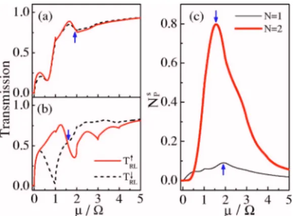
The nonlinear enhancement in the dc SC by two FGs 共N=2兲 is presented in Figs. 3共a兲–3共c兲. The driving frequency
FIG. 2. 共Color online兲 Spin-resolved current transmissions TRL↑ 共solid兲 and TRL↓ 共dashed兲 versus the incident energy/⍀.
Param-eters N = 1,␣0= 0.13, ⍀=0.002, l=20, and␣1=共a兲 0.03, 共b兲 0.04, and共c兲 0.05. The corresponding dc SC is plotted in 共d兲.
is chosen to be ⍀=0.001 共⬇14 GHz兲, and with l=22 共⯝88 nm兲. For comparison, the N=1 FG transmissions are plotted along with that of the N = 2 FG case, in Figs. 3共a兲 and 3共b兲, respectively. The corresponding dc SC, expressed in terms of pumped spins per cycle NP
s
=共2/⍀兲兩Is兩, is shown in
Fig. 3共c兲. The pumping is optimized by a choice of the FG separation, with the edge-to-edge separation ⌬l=22. The QBS dip structures are significant up to the fourth sideband in Fig. 3共b兲. As indicated by arrows, the pumped spin-per-cycle peaks at/⍀⯝1.57 共1.92兲, with peak value 0.8 共0.1兲 for the N = 2共N=1兲 FG case. The enhancement in NPs is far greater than doubling the NP
s
of N = 1 FG. Finally, we discuss the effectiveness of tuning␣. Grundler showed that a static FG bias change ⌬VFG⬃0.075 V can tune ⌬␣⬃0.25␣0.10
This tuning ability should remain valid in ac FG bias if the wave function in the asymmetric quantum well responses adiabatically. We estimate the quantum-well energy-level spacing ⌬E⬃0.08 eVⰇប⍀⬃0.06 meV, for ⍀/共2兲=14 GHz. Thus, the adiabatic response of the wave function in the quantum well is established. Furthermore, the ac FG biases, with amplitude⌬VFG⬃0.075 V, is estimated
to be within reach of coaxiable cable technology.17
V. CONCLUSION
In conclusion, a nonmagnetic way of generating dc SC has been established. The proposed Rashba-type quantum channel driven by an ac-biased finger gate is a simple struc-ture and should be within reach of recent fabrication capa-bility. The spin pumping is studied, in detail, in both its nature and its pumping mechanism. A resonant inelastic pro-cess is the major factor that contributes to the robustness of the spin pumping. The coherent nature of the pumping sup-ports further enhancement of the spin pumping by invoking configuration consisting of more than one finger gate.
ACKNOWLEDGMENTS
The authors acknowledge valuable discussions with A. G. Mal’shukov. This work was funded by the National Science Council of ROC under Grants No. NSC92-2112-M-009-035,
No. NSC92-2120-M-009-010, No. NSC93-2112-M-009-036, and No. NSC93-2119-M-007-002共NCTS兲.
APPENDIX A: WEAK-PUMPING (WP) REGIME
In the WP regime, we can obtain analytic results. The WP regime refers to the case when the Rashba coupling param-eter oscillates with a small amplitude␣1. Keeping only up to
the lowest nonvanishing contribution of ␣1, it is simpler to calculate the reflection amplitudes than the transmission co-efficients. The reflection amplitudes to m = ± 1 sidebands are first order in␣1and are the major objects of our calculation
here. The reflection amplitudes to m = 0 sideband, however, is second order in␣1 and is neglected. When the Rashba cou-pling parameter oscillates in time within a spatial region −l / 2⬍x⬍l/2, the longitudinal Hamiltonian is given by
Hx= − 2 x2+␣0y
冉
i x冊
+ ␣1cos⍀t 2 y ⫻冋
共l/2 − 兩x兩兲冉
i x冊
+冉
i x冊
共l/2 − 兩x兩兲册
, 共A1兲where共x兲 is the step function. For an electron incident from terminal L with wave vector kn,R 共E兲, the reflection coeffi-cients consist of contributions from reflections at the left and the right edges of the time-modulated region. We first calcu-late the reflection amplitudes due to reflection at x = −l / 2. The wave function is given by
n共x ⬍ − l/2兲 = e ikn,R 共E兲x e−iEt+
兺
m=±1 共m⫽0兲 rLm,e ikn,Lm,x e−i共E+m⍀兲t, 共A2兲 n共− l/2 ⬍ x ⬍ l/2兲 =兺
m=±1 共m⫽0兲 tL m, eikn,R m,x e−i共E+m⍀兲t + tL0,e ikn,R 共E兲x e−iEt冋
1 + 2⍀␣1kn,R 共E兲共e i⍀t − e−i⍀t兲册
. 共A3兲 Here, tLm,and rLm,denote, respectively, the transmission and reflection coefficients at the left edge of the time-modulated region. We have not included, in Eq.共A3兲, corrections to the wave functions associated with the coefficients tLm,, form = ± 1, that arise from the time-modulation of the Rashba
spin-orbit intraction共SOI兲. It is because the coefficients tLm,
are already first order in ␣1. These coefficients are solved from the wave-function continuous condition and the bound-ary condition in Eq. 共6兲. The reflection coefficients are cal-culated, and the expression is presented in Eq.共7兲. It is worth noting that tL0,= 1, up to first order in␣1.
Following a similar procedure, the reflection at the right edge of the time-modulated region can be obtained from the following wave function:
FIG. 3. 共Color online兲 Current transmission versus /⍀ for N =共a兲 1, and 共b兲 2. Pumped spins per cycle are plotted in 共c兲 for N = 1共thick curve兲 and N=2 共thin curve兲 with␣1= 0.065, and
n共− l/2 ⬍ x ⬍ l/2兲 = eikn,R 共E兲xe−iEt
冋
1 +␣1 2⍀ kn,R 共E兲共e i⍀t − e−i⍀t兲册
+兺
m=0,±1 rR m, eikn,L m,x e−i共E+m⍀兲t ⫻冋
1 +␣1 2⍀ kn,Lm,共ei⍀t− e−i⍀t兲
册
, 共A4兲n共x ⬎ l/2兲 =
兺
m=0,±1tRm,e ikn,Rm,x
e−i共E+m⍀兲t. 共A5兲 Again, tRm, and rRm, denote the transmission and the reflec-tion coefficients, respectively, at the right edge of the time-modulated region. It is noted that in Eq.共A4兲, only one in-cident wave needs to be considered. The inin-cident waves associated with coefficients tL
m,
in Eq.共A3兲, for m= ±1, is neglected because these coefficients are, themselves, first or-der in␣1. Invoking the wave-function continuous condition
and the boundary condition
x兩n 兩 x=共l/2兲−− x兩n 兩 x=共l/2兲+− i 2␣1cos⍀t兩n 兩 x=l/2= 0, 共A6兲 we obtain rRm,= − ei共kn,R −k n,L m,兲l rLm,, 共A7兲
and the total reflection coefficient, up to the first order in␣1
is given by rn,LLm,= rRm,+ rLm,, for m = ± 1, which explicit
ex-pression is presented in Eq.共8兲.
APPENDIX B: FORMULATION FOR NUMERICAL CALCULATION
The Hamiltonian in the ac-biased region, given by Eq. 共2兲, can have its time-modulated term transformed
away by the use of a transformation: ⌿n,共x,t兲
= exp关共␣1/⍀兲sin ⍀t共/x兲兴n共x兲, where n satisfies Eq. 共2兲 with␣1sets to zero. Thus, the general form of the wave
function in the time-modulated region is given by
⌿n,共x,t兲 = exp
冉
␣1 ⍀ sin⍀t x冊
冕
d关A˜n 共兲eikn,R 共兲x + B˜n共兲e ikn,L 共兲x兴e−it. 共B1兲The matching of the wave functions at all times requires the form F˜n共兲=兺m⬘Fn共m
⬘
兲␦共−n− m⬘
⍀兲.15 Hence, the nth-subband scattering wave function is of the form⌿n,共x,t兲 = eikn,R 共E兲xe−iEt+
兺
m rn,LLm,eikn,L m,x e−i共E+m⍀兲t, if x⬍ − l 2 共B2兲 ⌿n,共x,t兲 =兺
m,m⬘ 共−兲m−m⬘冋
An共m⬘
兲e ikn,Rm⬘,x Jm−m⬘冉
␣1 ⍀kn,R m⬘,冊
+ Bn共m⬘
兲eikn,L m⬘,x Jm−m⬘冉
␣1 ⍀kn,L m⬘,冊册
e−i共E+m⍀兲t, if兩x兩 ⬍l 2 共B3兲 ⌿n,共x,t兲 =兺
m tn,RLm,eikn,R m,x e−i共E+m⍀兲t, if x⬎ l 2. 共B4兲 By invoking the boundary conditions in Appendix A, the reflection and the transmission coefficients can all be solved.1Semiconductor Spintronics and Quantum Computation, edited by
D. D. Awschalom, N. Samarth, and D. Loss共Springer-Verlag, Berlin, 2002兲.
2S. A. Wolf, D. D. Awschalom, R. A. Buhrman, J. M. Daughton,
S. von Mohnár, M. L. Roukes, A. Y. Chtchelkanova, and D. M. Treger, Science 294, 1488共2001兲; Y. Kato, R. C. Myers, D. C. Driscoll, A. C. Gossard, J. Levy, and D. D. Awschalom, ibid. 299, 1201共2003兲; S. Murakami, N. Nagaosa, and S. C. Zhang, ibid. 301, 1348共2003兲.
3E. R. Mucciolo, C. Chamon, and C. M. Marcus, Phys. Rev. Lett.
89, 146802共2002兲.
4Experimental realization was reported by S. K. Watson, R. M.
Potok, C. M. Marcus, and V. Umansky, Phys. Rev. Lett. 91, 258301共2003兲.
5Q. F. Sun, H. Guo, and J. Wang, Phys. Rev. Lett. 90, 258301
共2003兲.
6A. Brataas, Y. Tserkovnyak, G. E. W. Bauer, and B. I. Halperin,
Phys. Rev. B 66, 060404共R兲 共2002兲.
7P. Zhang, Q. K. Xue, and X. C. Xie, Phys. Rev. Lett. 91, 196602
共2003兲.
8Y. A. Bychkov and E. I. Rashba, J. Phys. C 17, 6039共1984兲. 9J. Nitta, T. Akazaki, H. Takayanagi, and T. Enoki, Phys. Rev.
Lett. 78, 1335共1997兲.
10D. Grundler, Phys. Rev. Lett. 84, 6074共2000兲.
11P. Sharma and P. W. Brouwer, Phys. Rev. Lett. 91, 166801
共2003兲.
12M. Governale, F. Taddei, and R. Fazio, Phys. Rev. B 68, 155324
共2003兲.
13A. G. Mal’shukov, C. S. Tang, C. S. Chu, and K. A. Chao, Phys.
Rev. B 68, 23 3307共2003兲.
14P. F. Bagwell and R. K. Lake, Phys. Rev. B 46, 15329共1992兲. 15C. S. Tang and C. S. Chu, Phys. Rev. B 53, 4838共1996兲. 16G. Lommer, F. Malcher, and U. Rössler, Phys. Rev. Lett. 60, 728
共1988兲.