E L S E V I E R Materials Science and Engineering A215 (1996) 1 I3-119
M A T E R I A L S SCIENCE & ENGINEERING
A
A study on the wire drawing of TiNi shape memory alloys
S . K . W u a, H . C . L i n b, Y . C . Y e n c
aInstitute of Materials Science and EngineerOzg, National Taiwan University, Taipei, Taiwan 106, People's Republic of China bDepartment of Materials Science, Feng-Chia University, Taichung, Taiwan 400, People's Republic of China
°Department of Mechanical Engineering, Chin-Ming College, Miaoli, Taiwan 351, Republic of China
Abstract
Drawn wires of TiNi shape memory alloys (SMAs) have been studied systematically using DSC, microhardness, SEM and tensile tests. Severe work hardening during the drawing process is observed and hence interannealing is necessary. Multi-pass drawing around the Ms temperature is recommended. The defects induced by cold drawing depress martensitic transformation but promote the R-phase transformation. Defect recovery and recrystallization during interannealing are responsible for the decrease of drawing stress. At the same time, surface oxide film thickness is another important factor related to drawing stress. A thin surface oxide film can be used as a lubricant during the drawing process, however, thick oxide films tend to exhibit cracks and spalIing which decrease the drawing surface quality, shape memory effect and pseudoelasticity of TiNi SMAs. MoS2 is shown to be an effective lubricant for the wire drawing of TiNi SMAs.
Keywords: Shape memory aIIoys; Annealing; Pseudoelasticity; Lubricants
1. Introduction
TiNi alloys are an important class of shape memory alloys (SMAs). They exhibit not only the shape mem- ory effect (SME) [1], but also unusual pseudoelasticity [2,3] and high damping capacities [4,5]. These properties along with their superior ductility, strength, fatigue and corrosion resistance, have resulted in many applica- tions, among which use in the manufacture of wire forms figures prominently. In wire applications, TiNi SMAs are usually produced as wire springs, hollow wires and various nonregular shapes [6-9]. Recently, ultra-fine or hollow TiNi wires have been developed and have shown improved SME which is promoted by their higher cooling rates during the cooling process. There are many promising applications for these wires in products such as microactuators and microsprings. Therefore, the understanding of drawn wire properties is important for TiNi SMA applications.
As mentioned above, TiNi wire products have many potential applications, however, the roadblocks to their development are caused by difficulties in the manufac- turing process. It is well known that TiNi alloys can be tensile deformed in a ductile manner to more than 50% strain prior to fracture [1], but severe strain hardening accompanied by cold-working and wire-drawing hin-
ders their workability. To overcome this difficulty, some special wire drawing processes have been devel- oped such as the dieless drawing [10] and clad-chip extrusion [11]. However, even these new processes have some technical limits [10,11]. As we approach a solution to these problems, an understanding of the intrinsic wire drawing properties of TiNi SMAs becomes impor- tant. To the best of our knowledge, however, no sys- tematic investigation of the drawing properties of TiNi SMAs has been reported, although some papers have reported the effects of cold work and annealing on transformation temperatures [2,3,12-14]. In the present study, we aim to systematically investigate the wire drawing properties of TiNi SMAs under various draw- ing conditions. The surface oxide film and lubricants used in the drawing process are also discussed.
2. Experimental procedure
2.1. Materials preparation and the draw#zg process
A conventional tungsten arc-melting technique was employed to prepare TisoNis0, Ti49.7Niso.3, Ti49Ni51 al- loys. Titanium (purity, 99.7%) and nickel (purity, 99.98% totalling 100 g, were melted and remelted at
114 S.K. Wu et al./ Materials Science and Engineering A215 (1996) I13-I 19 least six times in an argon atmosphere. The weight loss
during melting was negligibly small. The as-melted buttons were homogenized at 1050 °C for 72 h and then hot-rolled at 850 °C to form plates 1.25 mm thick. Specimens for wire drawing (~ 1.2 mm x 300 mm) were carefully cut and ground from these plates. Before wire drawing, residual stress was removed and a thin oxide film was created by annealing for 10 min at 550 °C. The wires were drawn without the use of lubricants except for the process described in Section 3.4 in which one of the lubricants MoS2, oil, or soap was used during the drawing process.
The drawing machine and the wire head machine have been illustrated in a previous paper [15]. Single- pass or multi-pass drawing with or without lubricant can be conducted at a controlled speed ranging from 5-20 m min - ~. In the single-pass process, the set cross- section reduction is carried out by a single pass through one die. In the multi-pass process, the desirable cross section is obtained by multiple passes through several dies. Tungsten carbide dies are used for wire diameters > 100 gm and diamond dies are used for diameters < 100 lam. The drawing force during the wire drawing can be recorded in-situ by an S-type Load Cell. 2.2. Measurement techniques and equipment
The properties of TiNi SMAs drawn wire, including transformation temperatures, mechanical properties and some other interesting aspects were studied by differential scanning calorimetry (DSC), Vickers micro- hardness testing and tensile testing. DSC was con- ducted using a DuPont 9900 thermal analyzer equipped with a quantitative scanning system 910 DSC cell to control the heating and cooling rates on samples encap- sulated in an aluminum pan. Test temperatures ranged from - 60 °C to + 100 °C with a heating/cooling rate of 10 °C min-~. The heat of transformation, AH, was automatically calculated from the area under the DSC peak with the equipment software packages. Hardness testing was done using a Vickers microhardness tester with a 300 g load at room temperature. For each specimen, the hardness value, H~, was averaged from five test readings. Tensile tests were carried out using an UTM-3-500 type tensile tester with a strain rate of 5 mm min -
3. Results and discussion
3. I. The wire drawing stress of TiNi SMAs
Fig. 1 (a)-(c) show drawing stress and specimen hardness vs. the degree of cold work for the Tig9.7Nis0.s alloy tested at room temperature. Here the drawing stress is defined as the drawing force divided by wire
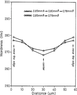
cross-sectional area and the degree of cold work is defined as the percent reduction in the wire cross-sec- tional area. In Fig. 1, the drawing stress and hardness are found to increase sharply with increasing degrees of cold work. These results reflect the severe work harden- ing that occurs in TiNi SMAs and that interannealing is necessary during the drawing process. One feature shown in Fig. l(a) and (b) is the large difference in drawing stress needed to obtain the same degree of cold work in between single-pass and multi-pass specimens. Obviously, the occurrence of this feature is because the strain rate of the single-pass process is larger than that of the multi-pass process for the same total cold-work- ing. Another important feature pertaining to the draw- ing process is the deformation homogeneity across the wire section. As shown in Fig. 2, for the drawn Tis0Ni~0 wires with the same degree of cold work, the two-pass drawing shows a more homogeneous hardness profile across the wire section than the single-pass drawing. This indicates that the multi-pass drawing exhibits a better deformation homogeneity. Thus, a multi-pass drawing is more suitable than a single-pass one to draw TiNi wires.
Fig. 3 shows the experimental results of the drawing stress vs. drawing temperature for as-annealed Ti49.TNi50.3 samples. The DSC result shows that this alloy has a start temperature of martensitic transforma- tion, Ms, at 23 °C, and a finish temperature of marten- sitic transformation, Mr, at 0 °C. In Fig. 3, the drawing stress has a minimum at about 25 °C. This phe- nomenon is very similar to TiNi bulk specimens [16] in
140 900 120 100 E --- 80 q) 60 ~ O 4 0 • ~ / 20 • /
/
0~ i 0 Ti49.7 Ni5o3 Ms = 23°C 1,4~ = 0 t _ (a) / //
Y
.,~.I"~(c)--
10 20 30 40 Degree of Cold Work (%)800 700 600 £ in c-
soo
U -r" 400 300 200 50 60Fig. 1. (a) The drawing stress of single-pass wire, Co) the drawing stress of multi-pass wire, (c) specimen hardness Hv, vs. the degree of cold work at room temperature for Ti49.7Nis0.3 alloy.
S.K. Wu et al. / Materials Science and Engineering A215 (I996) I13-119 115 300 ,'^^^ *. 0 85ram ~ 0.80mm{~ 0.78 ram, ~ O.85mm{~ O.78mrn~ 290- "9 E 280- g & % 260- 250 0 1 g g I I 10 2? 30 4~3 5'0 60 D i s t a n c e (,urn)
Fig. 2. The hardness curves across the wire section for TisoNiso wires drawn from 0.85 mm ~ to 0.78 mm 40.
which the tensile yield stress exhibits a minimum value around the Ms temperature. The curve minima in Fig. 3 shows that the wire drawing of TiNi SMAs will require lower stresses when carried out near the Ms temperature. This feature is closely related to the occur- rence of the "soft" mode which is associated with the martenstic transformation of TiNi SMAs [17,18]. Therefore, it is recommended that wire drawing pro- cesses of TiNi SMAs be performed at or near Ms temperature. 80 g- E E U) C3 75 70 a... 65 60. -100 -60 Ti497 Niso3 Ms = 23°C Mf =0%
/
-20 20 60 100 Temperature (°C)Fig. 3. The drawing stress vs. drawing temperature for the as-an- nealed Ti49 7Ni5o 3 wire.
.3.2. The effects of interannealing on the transformation temperature and drawing stress
As mentioned above, the work hardening of TiNi SMAs is quite severe and interannealing during the drawing process is necessary. Both the annealing tem- perature and time are important parameters which can affect transformation temperatures and drawing stress. Fig. 4(a)-(h) show some typical DSC curves for drawn TisoNis0 wires which have been 26.5% cold-worked, and then annealed at various temperatures and time peri- ods. Cold-worked specimens of other degrees have pro- duced similar results to those shown in Fig. 4 and therefore are omitted here. In Fig. 4, peaks R*, M* and A* indicate the transformations of parent B2 phase into rhombohedral premartensite R-phase, R-phase into martensite B19' phase and B19' phase into B2 phase, respectively. At the same time, in Fig. 4(a)-(g), one can find that the R-phase transformation appears prior to the martensitic transformation; therefore, the R-phase transformation can be induced by wire drawing fol- lowed by 300-600 °C interannealing. The residual in- ternal stress induced by cold-working defects is considered to be responsible for the R-phase transfor- mation [21,22]. In order to understand the effects of cold drawing and interannealing on the transformation temperatures, the experimental results of R* and M* vs. annealing time for different annealing temperatures are plotted in Fig. 5. In Fig. 5, under the same degree of cold work, R* slowly decreases, but M* quickly increases with increasing annealing time. This shows that the defects induced by cold drawing depress the martensitic transformation but promote the R-phase transformation. During the annealing, these defects continuously die out, and the residual internal stress also decreases simultaneously. Therefore, the effects of cold drawing on transformation temperatures decrease with increasing annealing time. This leads to the feature that R* temperature decreases, while M* temperature increases with the increasing annealing time, eventually merging R* and M* temperatures. As shown in Fig. 4(h) and 5, this merging time is about 30 min for 600 °C annealing, and about 70 min for 550 °C annealing. Fig. 6 shows the drawing stress at 10.43% cold working for the 26.5% pre-drawn TisoNis0 specimens interannealed at various temperatures and time periods. The drawing stress for specin~ens interannealed at higher temperatures is found to be lower. Defect recov- ery and recrystallization during the interannealing pro- cess are responsible for this feature. Drawing stress decreases to a low value with a 10 min annealing treatment at 600 °C. However, the 300 °C x 10-60 min interannealing has no effect on the drawing stress be- cause defect recovery and recrystallization are almost negligible.
t 16 S.K. Wu et aL / Materials Science and Enghwerhzg A215 (1996) 1 I3-119 I, 0 - r (a) M ~ 300°Cxl0min -26.~C R* M,X" ~: o ( b ) -21.2°c 39.2+c 300 Cx60min , ~ . 2.5 j/9 (d) A*V47.¢C Mi+
O0°Cx6Or n
- " R • 5.5 J/9 - 8 0 - 6 0 - / - + 0 - 2 0 0 20 40 60 80 100 Temperature (°C) (e) M+ R~ 500°Cxl0min -16.2eC 39.4°C----'52-
,o*
(f
1.7°c
, t R ~sy"
1.3"C 60rninL
" " _ 2o.2c s13Oc ~ / ' A* j / ~ L, 600°¢xlOmin ' ~ . s J/9 24.4a/9 (h) 3o.o°cX t 600*Cx60min 2s ? J/g . ' , 2 6 . 1 J/9 , ) I l I I l -20 0 20 40 60 B0 100 Temperature (°C)Fig. 4. Some typical DSC curves for drawn TisoNiso wires with 26.5% cold-working and then annealing at various temperatures and time periods. (a) 300 °C x 10 min, (b) 300 °C x 60 min, (c) 400 °C x 10 min, (d) 400 °C x 60 min, (e) 500 °C x 10 min, (f) 500 °C x 60 min, (g) 600 °C x 10 min, (h) 600 °C x 60 min. Noted that peaks R*, M* and A* represent B2 ~ R-phase transformation, R-phase ~ M19' martensitie transformation and B19'--, B2 reversed martensitic transformation.
3.3. The effects of oxide film on wire drawhTg
Some studies have reported that the surface oxide film can be used as a lubricant during the TiNi wire drawing process [6-8]. In order to further understand the effects of oxide film on TiNi wire drawing, surface- cleaned and annealed TisoNiso wires were heated in normal atmosphere at 550 °C for different time periods to obtain different thickness of surface oxide film. The surface-cleaning and the subsequent annealing pro- cesses used in this study are as follows. TisoNiso wires were first acid-cleaned ultrasonically in a solution of HF:HNO3:H:O = 1:5:20 by volume ratio for 20 min. The surface-cleaned Ti~oNiso wires were then encapsu- lated in a quartz tube and evacuated to 10 . 6 torr, solution-treated at 850 °C x 2 h and then water- quenched. After completion of the surface-cleaning and annealing processes, the TisoNis0 wires have a bright surface with unobservable surface oxide.
Fig. 7 shows the measured thicknesses of oxide films vs. heating time for surface-cleaned and annealed
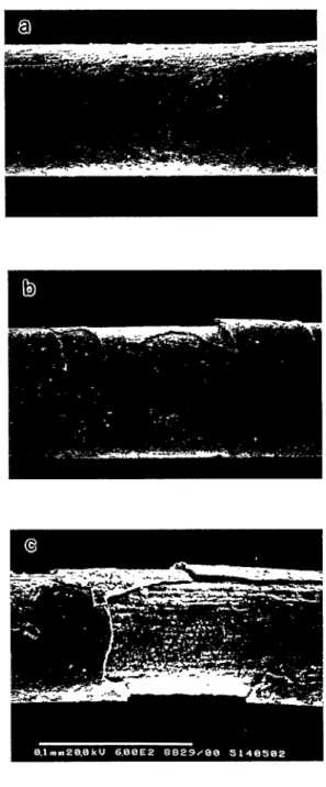
TisoNis0 wires heated at 550 °C for various time peri- ods. The thickness measurement is based on the SEM observations of oxidized specimens at 20000 x [19]. The drawing stresses vs. different heating times at 14.3% cold work (from qb = 0.81 mm to qb = 0.75 mm), i.e., under different thicknesses of oxidation film, are also shown in Fig. 7. As shown in Fig. 7, the drawing stress decreases sharply in the early 20 min of heating time and then maintains a low value, though the thick- ness of the oxide film monotonously increases with heating time. This indicates that a thin oxide film is sufficient for use as a lubricant during the drawing. In contrast, a thick oxide film wilt damage drawing prop- erties. Fig. 8(a)-(c) show SEM observations of 80
J.lmqb
fine TiNi wires after interannealing at 550 °C x 10 rain, 550 °C x 70 min and 700 °C x 10 min, respectively. Fig. 8(a) shows a smooth surface and a thin oxide film, but Fig. 8(b) and (c) exhibit thick oxide films with cracks and spalling on the surfaces. These surface cracks and spatting only occur in thick films which have been identified as TiO: [20]. Obviously, the thickness of100 550°cR: s o - OJ 13- E 10-
-lO- ~
*
4oo°c ~4 ~ -30 ~ l t I I l 10 20 30 40 50 60 Heating Time (min)Fig. 5. R* and M* temperatures vs. annealing time for different annealing temperatures of TisoNiso wires. The wires' degree of cold work is 26.5%.
oxide film increases with higher annealing temperatures and longer annealing time periods. In this study, the heating/interannealing condition of 550 °C x 10 rain in atmosphere results in a thickness of oxide film adequate to serve as a lubricant and TiNi wires can be drawn to below 30 gm(~ under this heating/interannealing condi- tion. It is not possible to draw to ultrafine wires from wires with a thick oxide layer owing to the detrimental effects of thick oxide on the wire's surface quality which easily causes the wires to break.
Another disadvantage of the thick oxide film formed on TiNi wires is that it can depress TiNi SMAs' shape memory effect and pseudoelasticity. One example is shown in Fig. 9 in which the pseudoelasticity behavior of 700 °C x 10 min interannealed Ti49Ni51 50 lam d? wire is plotted. The pseudoelasticity of this fine wire is worse ( < 40% recovery for the 8% strain) than the Ti49Ni51 bulk specimen [3]. Two factors might be responsible for
[ i 95 04
85
£5
#8o C3 75 70, 0S.K. IVu et al./ Materials Science and Engineer#Tg A215 (1995) i13-1 I9 117
0.500 0.417 0.333 ~: Ff - - 0250 3
"5
0167 0.083 0 10 20 30 40 50 60Heating Time (rain)
Fig. 7. The measured thickness of oxide film and the drawing stress vs. heating time at 550 °C for TisoNi.~o wires. The wires' degree of cold work is 14.3%.
this feature. First, the T i Q oxide film at the surface does not exhibit the shape memory effect and pseudoe- lasticity. Second, the introduction of oxygen atoms at the subsurface can depress the martensitic transforma- tion to a lower temperature [16], and hence the Ma temperature near the Ti49Ni51 wire surface may be lower than room temperature. Here, Md is a tempera- ture above the Ms, and for temperatures between Ma and Ms, TiNi SMAs can exhibit the pseudoelasticity. Therefore, the pseudoelastic behavior tested at room temperature is worse because a lower volume of stress- induced martensite can occur in the whole wire. Hence, the oxide film should be removed to improve the shape memory effect and pseudoelasticity after the drawing process has been completed.
150
g-130 ~ X
~
o
o
ooooo 300°C 110 \ \ ~ D r ~ s 4 0 0 ° C ..~ \ \ ~ ~ - ~ a 500°C v ^ v $ ^ m 90 cn 7 0 - r- '~ 5 0 - tin 30 I I I I 1 I 10 20 30 40 50 60 70Heating Time (rain)
Fig. 6. The drawing stress at 10.43% cold work for the 26.5%
pre-drawn TisoNiso wires interannealed at various temperatures and time periods.
3.4. The effects of lubricants on the wire drawing In order to understand the effects of lubricants on the wire drawing, the lubricants MoS2, oil and soap were used in a three-pass drawing. Fig. 10 shows the drawing stress vs. degree of cold work for TisoNiso wires during the three-pass drawing (13.61%-->
17.94%-,22.15%). In Fig. 10, for all four tested TisoNiso wires tested with or without lubricant, the drawing stresses in the first pass have nearly the same values. However, in the second and third passes, draw- ing stresses were quite different, namely, MoS2 < oil < soap < none. The results can be explained as follows. In this study, before wire drawing, a thin oxide film was formed on the stress-relieved TisoNiso wires by heating at 550 °C for 10 rain. The oxide films exhibit important lubricating effects during the first-pass drawing,
1 I8 S.K. Wu et al./Materials Science and Engineering A215 (1996) 113-119
whether the wire surface has lubricant or not. Hence, the drawing stresses for all of the tested TisoNiso wires of Fig. 10 have nearly the same values. However, oxide films are destroyed or thinned after the first-pass draw- ing and thereafter resulting in a lower lubrication by the oxide films in the further drawings. Therefore, the lubricants MoS2, oil and soap plays an important role during the second and third pass drawings and the drawing stress with lubricant is comparably lower than that without lubricant. Among these lubricants, MoSa seems to be the most effective because the drawing stress with MoS2 lubricant is the lowest in Fig. 10. In addition, MoS2 lubricant is a Newtonian fluid, namely,
60 50 T" E E 40 30 m o l P 20 u3 10
J:/
4 % 6°/o (b) (c) (d)JlJ
, ! i o 8/o iOO/o (f) / 12°Io 15% Strain , 10°/o ,Fig. 9. The pseudoelastie behavior of 700 °C x I0 min interannealed Ti49Ni51 wire. The diameter of the wire is 50 gm, The tensile strain is (a) 4%, (b) 6%, (c) 8%, (d) 10%, (e) 12% and (f) 15%. The strain rate is 50 mm m i n - 1.
its viscosity coefficient is independent of flow rate [19], This feature can increase drawing stability and promote the drawn wire quality,
Fig. 8. The SEIVl observations of 80 gm ¢ fine TiNi wires after interannealing at (a) 550 °C x 10 min, (b) 550 °C x 70 min, and (c) 700 °C x i0 min respectively.
4. Conclusions
(i) The inherently severe work hardening properties in TiNi SMAs depress their drawing properties and interannealing is necessary. A multi-pass drawing at around the M~ temperature of TiNi SMAs is recom- mended.
(ii) Thin oxide film with a smooth surface on TiNi wires can be used as a lubricant during the drawing
110 occao None ¢~ ¢,00 Soep(liquid)
i •
1st Die I 14 16 18 ~ 1 0 0 - - r~mmmn MoS2 ~¢ . . . oil ' E 90 t t 3 ¢.. .~ 8o l::3 7O ~ n d Die/
/
/
n " ~ : . r d Die 12 20 22 24Degree of Cold Work (%)
Fig. 10. The drawing stress vs. the degree of cold work for Tis0Nis0 wires with or without lubricant. The lubricants used in the three-pass drawing are MoS2, oil, and soap. The degrees of cold work are first die i3.61%, second die 17.94% and third die 22.I5%
S.K. W,~ et al. / Materials Science and Engineering A215 (i996) i13-119 119 process. However, thick oxide films which have cracks
and spalling on the surface can be detrimental to the drawing surface and depress the shape memory effect and pseudoelasticity of TiNi SMAs.
(iii) MoS2 is an effective lubricant for wire drawing of TiNi SMAs.
Acknowledgements
The authors are pleased to acknowledge the financial support of this research by Tjing Ling Industrial Re- search Institute, National Taiwan University, under Grants 82-G-10 and 83-G-10, and by National Science
Council (NSC), Republic of China, under Grant
N S C 8 3 - 0 4 0 5 - E 0 0 2 - 0 1 1 .
References
[1] S. Miyazaki, K. Otsuka and Y. Suzuki, Scr. Metall., I5 (1987) 287.
[2] S. Miyazaki, Y. Ohmi, K. Otsuka and Y. Suzuki, d'. Phys., 43 (1982) C4-255.
[3] S. Miyazaki, T. Imai, Y. Igo and K. Otsuka, Metall. Trans., 17A (1986) 115.
[4] H.C. Lin, S.K. Wu and M.T. Yeh, Metatl. Trans., 24A (1993) 2189.
[5] H.C. Lin, S.K. Wu and Y.C. Chang, Metall. Trans., 26,4 (1995). [6] C.M. Jackson, H.J. Wagner and R.J. WasiIewski, NASA-
SP51IO (i972) 19.
[7] W.J. Buehler and W.B. Cross, Wire J., June (1969) 41. [8] M. Aiba, H. Nagai and M. Asakawa, Mater. Jpn., JIM, 3I (6)
(I992) 54I (In Japanese).
[9] K. Yoshida and H. Tanaka, Wire, 45 (1995) 2.
[10] Y. Kawaguchi, K. Katsube, M. Murahashi, Y. Yamada, Wire J.,
12 (1992) 53.
[11] S. Saito, T. Wachi and S. Hanada, Mater. Sci. Eng., AI61 (1993) 91.
[12] Y. I.iu and P.G. McCormick, Acta Metall. Mater., 38 (1990) 1321.
[13] Y. Liu and P.G. McCormick, ISU, 29 (1989) 417.
[14] P.E. Thoma, M.Y. Kao, S. Fariabi and D.N. Abujudom, ICO-
M A T (I992) 917.
[15] H.C. Iin, S.K. Wu and Y.C. Yen, Proc..PRICM-2, Kyongju, Korea, 1995, in press.
[16] H. Funakubo, Shape Memory Alloys, translated by J.B. Kennedy, Gordon and Breach Science, New York, 1984, Ch. 2. [17] Z. Nishiyama, Martensitic Transformation, Academic Press, New
York, I978, Ch. 3.
[18] A.I. Lotkov, A.V. Kuznetsov, V.N. Griskov and A.A. Botaki, in Y. Chu, T.Y. Hsu and T. Ko (eds.), Proc. b~t. Shape Memory
Alloy Syrup., Guilin, China, i986, p. 153.
[19] J.C. Chert, Master Thesis, Department of Mechanical Engineer- ing, National Taiwan University, 1995.
[20] C.L. Chu and S.K. Wu and Y.C. Yen, Mater. Sci. Eng. A, (1996) in press.
[21] H.C. Lin, S.W. Wu, T.S. Chou and H.P. Kao, Acta Metall.
Mater., 39 (1991) 2069.