The formation mechanism of the distinctive microstructure is attributed to the inclined anchoring effect, and the relaxation of internal stresses, which were induced by the confined pyrolysis process, resulting in easier disintegration by sonication the nanofilaments. This is disclosed for the first time in literature regarding the attainment of uniform carbon nanoparticles.
Introduction
Carbon nanoparticles consisting of conical graphene stacking is important in both science and engineering aspects. Potential applications such as enhanced field emission sources and catalyst supports are under rigorous development,1-3due to their specific electronic states predicted by theoretical calculations,4,5as well as the good balance between chemical reactivity and structural strength attributed to the graphene arrangement. Their high-efficiency electrochemical capacities was also demonstrated in comparison to other carbon materials with different microstruc-tural alignments.6 In general, conical carbon materials were synthesized by pyrolysis of hydrocarbons with metal clusters. In this case, their conical topography is dominated by the surface morphology of catalysts.7 In addition, natural graphite cones could be found in graphite minerals.8On the basis of the stacking form of microstructure, there are three major types of conical carbon nanomaterials: a cup-stacked (stacked closed cones) type,9,10 a lampshades (stacked open cones) type,11,12and an
acute angle (graphite cones) type.13-15Two theoretical micro-structure models, closed cone model9,16 and cone-helix model,8,17,18have been proposed, respectively, to describe geo-metric organization of the conical graphenes.19The closed cone model demonstrates the formation of conical graphene by introducing pentagonal rings into the honeycomb graphene layer. The cone-helix model illustrates a helical stacking with con-tinuously wrapping graphene by applying a parameter of the overlap angle.
In this study, uniform carbon nanoparticles with specific shapes were obtained using sonication of the carbon nanofilaments synthesized by a template method.20Characteristic morphologies of the nanoparticles which had never been reported in literature are disclosed herewith. Both the structure and the formation mechanism of the resultant nanodiscs and nanocones are further demonstrated and discussed. The microstructure studies showed that the nanoparticles formed an unusual graphene arrangement, which does not agree well with the existing models. This unusual stacking form will be taken into account in our modified cone-helix model.
Experimental Section
The precursor was petroleum pitch (A-240, Ashland Inc.) composed of discotic hetero-polycyclic aromatic hydrocarbons (PAHs) units, and the porous anodic aluminum oxide with nanosized channels was used as templates. The preparation of carbon nanofilaments is shown in Supporting Information Scheme S1, and the details can be found elsewhere.20,21 The nanofilaments were
annealed at 2400°C for 5 h in a graphitization furnace to attain a graphitic structure with better crystallinity. The destacking of nanofilaments was performed in a sonication bath at 1000 Hz for 3 h. The final products were characterized by a scanning electron * Corresponding author. E-mail address: [email protected]. Tel:
+886 3 5742630. Fax: +886 3 5719868.
†Department of Materials Science and Engineering, National Tsing Hua
University.
‡Nano and Materials Science Center, National Tsing Hua University. §National Chiao Tung University.
|Feng-Chia University.
(1) Li, J. J.; Gu, C. Z.; Wang, Q.; Xu, P.; Wang, Z. L.; Xu, Z.; Bai, X. D. Appl. Phys. Lett. 2005, 87, 143107.
(2) Endo, M.; Kim, Y. A.; Ezaka, M.; Osada, K.; Yanagisawa, T.; Hayashi, T.; Terrones, M.; Dresselhaus, M. S. Nano Lett. 2003, 3, 723-726.
(3) Yoon, S. H.; Park, C. W.; Yang, H. J.; Korai, Y.; Mochida, I.; Baker, R. T. K.; Rodriguez, N. M. Carbon 2004, 42, 21-32.
(4) Berber, S.; Kwon, Y. K.; Tomanek, D. Phys. ReV. B 2000, 62, 2291-2294. (5) Munoz-Navia, M.; Dorantes-Davila, J.; Terrones, M.; Terrones, H. Phys. ReV. B 2005, 72, 235403.
(6) Kim, T.; Lim, S.; Kwon, K.; Hong, S. H.; Qiao, W. M.; Rhee, C. K.; Yoon, S. H.; Mochida, I. Langmuir 2006, 22, 9086-9088.
(7) Rodriguez, N. M.; Chambers, A.; Baker, R. T. K. Langmuir 1995, 11, 3862-3866.
(8) Jaszczak, J. A.; Robinson, G. W.; Dimovski, S.; Gogotsi, Y. Carbon 2003, 41, 2085-2092.
(9) Krishnan, A.; Dujardin, E.; Treacy, M. M. J.; Hugdahl, J.; Lynum, S.; Ebbesen, T. W. Nature (London) 1997, 388, 451-454.
(10) Terrones, H.; Hayashi, T.; Munoz-Navia, M.; Terrones, M.; Kim, Y. A.; Grobert, N.; Kamalakaran, R.; Dorantes-Davila, J.; Escudero, R.; Dresselhaus, M. S.; Endo, M. Chem. Phys. Lett. 2001, 343, 241-250.
(11) Ren, W. C.; Cheng, H. M. Carbon 2003, 41, 1657-1660.
(12) Endo, M.; Kim, Y. A.; Hayashi, T.; Yanagisawa, T.; Muramatsu, H.; Ezaka, M.; Terrones, H.; Terrones, M.; Dresselhaus, M. S. Carbon 2003, 41, 1941-1947.
(13) Gogotsi, Y.; Dimovski, S.; Libera, J. A. Carbon 2002, 40, 2263-2267.
(14) Muradov, N.; Schwitter, A. Nano Lett. 2002, 2, 673-676. (15) Zhang, G. Y.; Jiang, X.; Wang, E. G. Science 2003, 300, 472-474. (16) Zhu, Y. A.; Sui, Z. J.; Zhao, T. J.; Dai, Y. C.; Cheng, Z. M.; Yuan, W. K. Carbon 2005, 43, 1694-1699.
(17) Double, D. D.; Hellawell, A. Acta Metall. 1974, 22, 481-487. (18) Eksioglu, B.; Nadarajah, A. Carbon 2006, 44, 360-373.
(19) Kim, Y. A.; Hayashi, T.; Naokawa, S.; Yanaisawa, T.; Endo, M. Carbon 2005, 43, 3005-3008.
(20) Lin, C. T.; Chen, W. C.; Yen, M. Y.; Wang, L. S.; Lee, C. Y.; Chin, T. S.; Chlu, H. T. Carbon 2007, 45, 411-415.
(21) Masuda, H.; Fukuda, K. Science 1995, 268, 1466-1468. 10.1021/la701949k CCC: $37.00 © 2007 American Chemical Society
microscope (SEM, JEOL JSM-6500F at 15 kV) and a high-resolution transmission electron microscope (HRTEM, JEOL JEM-2010).
Results and Discussion
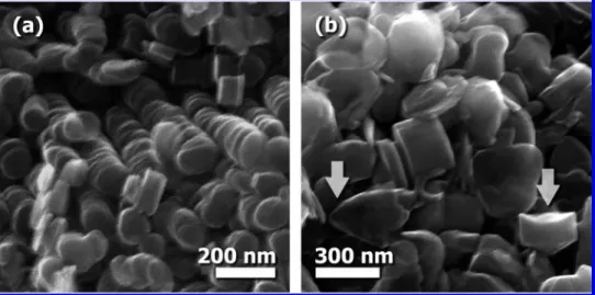
After sonication in an ethanol solvent, the as-prepared carbon nanofilaments, with two different diameters, were disintegrated entirely to form countless nanoparticles, as shown in Figure 1a,b. Disc-like nanoparticles are manifested in Figure 1a, while a mixture of conical and disc-like nanoparticles can be observed in Figure 1b. The diameters of these nanoparticles are 120 ( 20 nm (Figure 1a) and 300 ( 50 nm (Figure 1b), respectively, cor-responding to those of original nanofilaments. The thickness is in the range 10-100 nm. As the large-pore-sized template was used, both conical and disc-like nanoparticles are found in the products, whereas only disc-like nanoparticles can be observed from the small-pore-sized template. Therefore, one or two kinds of nanoparticles: carbon nanodiscs and nanocones, named after their contours, can be obtained via destacking of herringbone-type nanofilaments with different diameters by mechanical treatment.
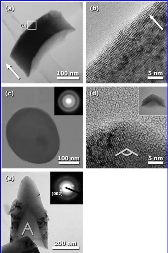
The side view of a nanodisc in Figure 2a shows the thickness of∼100 nm. Thinner nanodiscs were difficult to see, since they tend to lie flat on the supporting film of TEM grids and become quite “transparent” to the electron beam. The lattice image (Figure 2b) enlarged from Figure 2a shows that the orientation of stacked graphenes of the nanodisc is parallel to the circular plane. The inset diffraction pattern in Figure 2c reveals that the nanodisc is amorphous. The blurred rings can be approximately assigned to (100) and (110) planes, indicating that the microstructure of the nanodisc is stacked in a turbostratic arrangement. The absence of (002) diffraction spots in this pattern is ascribed to the fact that the c-axis of graphite is parallel to the incident direction of the electron beam. This agrees with the microstructural observa-tion in Figure 2b. There are no evident cracks or fractures in the top-view micrograph of the nanodisc (Figure 2c), suggesting that the mechanical treatment will not damage the basal structure. Figure 2d,e shows the TEM images of the obtained carbon nanocone. The lattice image (Figure 2d) enlarged from the apex of the nanocone exhibits how parallel basal planes follow the conical outline. The apex angle is measured to be∼120.5°. It shows that a symmetry line along the central axis classifies the graphene stacking into two groups. Typical nanocones obtained in this experiment have a tapered and a funnel-shaped end with different apex (cone) angles (Figure 2e). The inconsistent apex angles of nanocone ends are distinctive and can be observed
only in our nanoparticles. Two sets of (002) diffraction spots exhibited in the inset of Figure 2e suggest the conical graphene stacking. The cross-angle between the sets of spots, known to correlate directly with the average apex angle of the nanocone, is about 34°. Yoon et al. found that the catalytically grown carbon nanofibers consist of assemblages of small substructures, which are called carbon nanorods and nanoplates.22,23The substructures are considered the basic building units for diverse fibrous nano-carbons. Despite our nanoparticles being made from template-synthesized nanofibers, they can be considered the fundamental building blocks for the original nanofibers as well. However, the circular periphery of our nanoparticles is distinct from the above-mentioned substructures, which usually show a polygonal contour. The graphene arrangement of the nanoparticles is studied in detail by considering the current conical graphene models. According to the closed cones model,9,16the planar topography of the nanodisc should reveal stacking with graphenes composed of hexagonal carbon rings only. As the pentagon rings were introduced in part into hexagonal networks, the pentagonal “defects” will curve the planar structure to form the conical shape. In terms of Euler’s theorem and the symmetry of graphenes, there are five possible apex angles that are geometrically permitted by inserting pentagons from one ring to five rings into the hexagonal framework, resulting in apex anglesθ ) 19.2°, 38.9°, 60.0°, 83.6°, and 112.8°respectively. The values of apex angle, θ, are given by
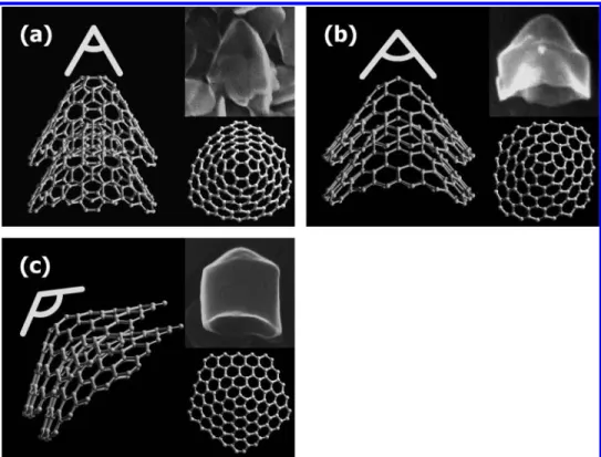
where n is the number of incorporated pentagons. The simulated molecular structure of the graphenes with pentagon defects is built by Hyperchem and illustrated in Figure 3. Nanocones with distinguishable apex angles corresponding to the molecular models can be found in our samples, as shown in Figures 2e and 3a,b,d. The apex angles were measured to be 38°, 57°, 78°, and 112°, respectively. The measurement error of 0.7-7% is due to the random inclination of the nanocones with respect to the observation direction.
Although the closed cones model defines five kinds of seamless folding of graphene cones, various apex angles that do not coincide with this model are still observed. The cone-helix model8,17,18 (22) Yoon, S. H.; Lim, S.; Hong, S. H.; Qiao, W. M.; Whitehurst, D. D.; Mochida, I.; An, B.; Yokogawa, K. Carbon 2005, 43, 1828-1838.
(23) Lim, S.; Hong, S. H.; Qiao, W. M.; Whitehurst, D. D.; Yoon, S. H.; Mochida, I.; An, B.; Yokogawa, K. Carbon 2007, 45, 173-179.
Figure 1. SEM images of the resultant products: (a) disc-like nanoparticles and (b) mixture of the disc-like and conical (arrowed) nanoparticles found after sonication treatment.
is then considered because it is able to account for conical graphenes of most apex angles, including the five from the closed cones model. The cone-helix model is constructed by introducing a parameter, the overlap angle, to estimate the overlapping degree of wrapped graphene sheets, resulting in the various conical graphenes. Another parameter, the degree of graphitic alignment, was adopted to justify if the overlapped graphenes are energeti-cally stable enough. It evaluates how many carbon atoms among the layers can achieve the alignment of lattice points in graphite crystal. When the two parameters are combined, a series of conical graphenes with all possible apex angles can be generated (see
Table S1 in Supporting Information). Our products always have a pair of tapered and funnel-shaped ends with different apex (cone) angles. The angles of any ends agree with one of proposed angles from the cone-helix model. For instance, the angles of the nanocone in Figure 2e are 30°(funnel-shaped end) and 38° (tapered end), which can be assigned to the overlap angles of 240.0°and 267.8°, respectively.
Despite the fact that microstructure at each end of the nanocone was expounded well by a cone-helix model, it still cannot explain why the two ends have different apex (cone) angles. In fact, the apex (cone) angles of the conical graphene stacking in nanocones Figure 2. TEM microstructure of the carbon nanoparticles: (a) the cross-sectional view of a nanodisc, and (b) lattice image enlarged from (a) revealing the orientation of stacked graphenes; (c) top view of the nanodisc; (d) lattice image of a nanocone, and (e) the low-magnification image of the nanocones; two sets of (002) diffraction spots are observed in the inset diffraction pattern.
increase continuously from funnel-shaped end to tapered end. This is different from any reported conical carbon materials with regular apex angles, which can be perfectly interpreted by the cone-helix model. Furthermore, it is noticed that the average interlayer spacing has a∼4.6% difference between the peripheral and central parts of the nanocones (see Figure S1 in Supporting Information). This difference is small and not easily observed. In contrast, the interlayer spacing among stacked graphenes developed from the cone-helix model or closed cones model should be identical everywhere. To summarize the discussion with the stacking form of the nanocones, a possible extension of the cone-helix model is proposed. The nanocone is constructed by the stacking of conical graphenes with progressively increasing apex (cone) angles (decreasing overlap angles) from funnel-shaped end to tapered end. The comparative schematics of current and modified cone-helix structure are shown in Scheme 1.
The formation mechanism of the nanoparticles is attributed to both confined pyrolysis process and inclined anchoring effect.
In the softening stage, the channels of the template were impregnated with liquid-phase precursor. The arrangement of discotic hetero-PAHs units in softened precursor was dominated by the competition between the self-assembly arisen from the van der Waals force and the bonding to the template surface by the anchoring effect.24The previous studies have demonstrated that in our experiment the PAH units in the liquid-phase precursor would show the edge-on state but not anchor on the template surface with an orthogonal angle.20 The “inclined” edge-on anchoring in our products is distinctive from that mentioned in other literature.24This competition caused the hetero-PAHs units, which are not stacked, to follow the lowest energetic way as the cone-helix model defines, and the pyrolysis process that followed forced the graphene framework to be established simultaneously in the confined channels, generating internal stresses that result in structural instability. Usually, the conical carbon nanomaterials were synthesized by a catalytic pyrolysis method in which the graphenes were stacked layer by layer on the metal catalysts, so the internal stresses were released during the growth process. The relaxation of internal stresses plays a crucial role in disintegrating the nanofilaments forming the nanoparticles under an applied mechanical force. It is suggested that whether or not sliding occurs at interface of the conical graphenes is dependent on whether the cone angles are energetically stable or not, in a relative sense.
Conclusions
Carbon nanoparticles, like nanodiscs and nanocones, with specifically controllable morphologies can be prepared by sonication treatment of herringbone-type nanofilaments syn-thesized by the template method. The formation mechanism is attributed to the relaxation of internal stresses generated by both the confined pyrolysis process and the inclined anchoring effect, resulting in structural instability. The arrangement of stacked (24) Chan, C.; Crawford, G.; Gao, Y. M.; Hurt, R.; Jian, K. Q.; Li, H.; Sheldon, B.; Sousa, M.; Yang, N. Carbon 2005, 43, 2431-2440.
Figure 3. Microstructural models of the nanocones using the closed cones model: introducing (a) 3 pentagons, (b) 2 pentagons, and (c) 1 pentagon into the hexagonal graphene sheets, generating the conical graphenes with apex angles ofθ ) 57°, 78°, and 112°.
Scheme 1. Comparative Schemes: (a) Current Cone-Helix Structure Stacked by Conical Graphenes with Constant
Apex (Cone) Angles; (b) Modified Model Showing the Conical Graphenes Stacked with Progressively Apex (Cone)